Monogram ZIF361NPRII User manual

INSTALLATION
INSTRUCTIONS
18”, 24”, 30” and 36” Built-In Column Freezers
24”, 30” and 36” Built-In Column Refrigerators
MONOGRAM.COM
Pour obtenir une version française de ce manuel, visitez notre
site web sur monogram.com.
Para consultar una version en español de este manual de instrucciones,
visite nuestro sitio de internet monogram.com.

231-1000600 Rev. 0
BEFORE YOU BEGIN
Read these instructions completely and carefully.
• IMPORTANT – Save these instructions for
local inspector’s use. Observe all governing codes and
ordinances.
• Note to Installer – Be sure to leave these
instructions with the Consumer.
• Note to Consumer – Keep these instructions with
your Owner’s Manual for future reference.
If you received a damaged unit, you should immediately
contact your dealer or builder.
Skill Level – Installation of this unit requires basic
mechanical, carpentry and plumbing skills. Proper
installation is the responsibility of the installer. Product
failure due to improper installation is not covered under
the Monogram Warranty. See the Owner’s Manual for
warranty information.
Safety Information
WARNING Tip Over Hazard.
These appliances are top heavy, especially with any doors open, and must be secured to prevent tipping forward
which could result in death or serious injury. Read and follow the entire installation instructions for securing the appli-
ance with the anti-tip system.
WARNING Fire or Explosion Hazard.
Keep flammable materials and vapors away from appliance. Failure to do so can result in fire, explosion,
or death.
WARNING To reduce the risk associated with choking, do not allow children under 3 years of age to have
access to small parts during the installation of this product.
CAUTION Lifting Hazard
This unit is very heavy. To reduce the risk of person injury during maneuvering and installing this appliance, 3 people
are required for proper installation.
CAUTION Keep fingers out of the “pinch point” areas; clearances between the doors and between the
doors and cabinet are necessarily small. Be careful closing doors when children are in the area.
PROPER DISPOSAL OF YOUR APPLIANCE
Dispose of or recycle your appliance in accordance with Federal and Local Regulations. Contact your local authorities
for the environmentally safe disposal or recycling of your appliance.
ŶConsider recycling options for your appliance packaging material.
WARNING Electrical Shock Hazard.
Plug into a grounded 3-prong outlet.
Do not remove the ground prong.
Do not use an adapter.
Immediately discontinue use of a damaged supply cord.
If the supply cord is damaged it must be replaced by a
qualified service professional with an authorized service
part from the manufacturer.
Do not use an extension cord with this appliance.
Failure to follow these instructions can result in death,
fire, or electrical shock.
Follow the instructions in the section Grounding the unit.
This appliance must be installed with a means in the fixed
house wiring or circuit breaker for disconnecting the appli-
ance from the electrical supply after installation.

3
31-1000600 Rev. 0
Safety Information
MISE AU REBUT ADÉQUATE DE VOTRE ÉLECTROMÉNAGER
Veuillez jeter ou recycler votre électroménager conformément aux règlements fédéraux ou locaux. Communiquez avec les
instances locales pour en savoir plus sur la mise au rebut ou le recyclage de votre électroménager.
Ŷ&RQVLGpUH]OHVRSWLRQVGHUHF\FODJHGHVPDWpULDX[G¶HPEDOODJHGHYRWUHpOHFWURPpQDJHU
AVANT DE COMMENCER
Veuillez lire toutes ces instructions attentivement.
• IMPORTANT – Conservez ces instructions à
l’usage de l’inspecteur local. Observez tous les codes et
décrets en vigueur.
• Note à l’installateur – Assurez-vous de laisser ces
instructions au consommateur.
• Note au consommateur - Conservez ces instructions
avec votre manuel d’utilisation pour consultation ultérieure.
Si vous avez reçu un appareil endommagé, veuillez
communiquer immédiatement avec votre revendeur ou votre
entrepreneur.
Niveau de compétence – L’installation de cet appareil
exige des compétences de base en mécanique, menuiserie
et plomberie. La responsabilité d’une installation adéquate
relève de l’installateur. La garantie Monogram ne couvre
pas les défectuosités du produit causées par une installation
inadéquate. Consultez le manuel d’utilisation pour des
renseignements sur la garantie.
AVERTISSEMENT Risque de basculement.
Ces électroménagers sont lourds du haut, notamment lorsqu’une porte est ouverte, de sorte qu’ils doivent être fixés pour prévenir
un basculement vers l’avant susceptible d’occasionner des blessures graves ou la mort. Lisez et observez la totalité des instruc-
tions d’installation pour connaître la façon de fixer l’électroménager sur le dispositif antibasculement.
AVERTISSEMENT Risque d’incendie ou d’explosion.
Gardez les matières et les vapeurs inflammables à distance de l’électroménager. L’omission de prendre cette précaution peut
entraîner un incendie, une explosion ou la mort.
AVERTISSEMENT Pour réduire le risque d’étouffement pendant l’installation de ce produit, ne pas laisser les petites pièces
à la portée des enfants âgés de moins de 3 ans.
AVERTISSEMENT Risque lié à la manipulation d’un objet lourd
Cet appareil est très lourd. Afin de réduire le risque de blessure pendant la manipulation et l’installation de cet électroménager, la
participation de 3 personnes est nécessaire à l’exécution d’une installation correcte.
AVERTISSEMENT Gardez vos doigts éloignés des points de pincement. Les espaces entre les portes et ceux entre les
portes et l’armoire sont particulièrement restreints. Soyez prudent lorsque vous fermez les portes en présence d’enfants.
AVERTISSEMENT Risque d’électrocution.
Branchez l’appareil dans une prise à 3 broches mise à la terre.
N’enlevez pas la broche de mise à la terre.
N’utilisez pas un adaptateur.
Cessez immédiatement l’utilisation d’un cordon électrique
endommagé. Si le cordon électrique est endommagé, son rem-
placement doit être exécuté par un technicien en réparation qua-
lifié au moyen d’un cordon de rechange autorisé par le fabricant.
N’utilisez pas un cordon de rallonge avec cet électroménager.
Le non-respect de ces instructions peut occasionner un décès,
un incendie ou un choc électrique
Suivez les instructions de la section Mise à la terre de l’appareil.
Le circuit électrique auquel cet électroménager sera raccordé
doit comporter un disjoncteur ou un autre dispositif permettant
de couper l’alimentation électrique à l’appareil après l’installation.

431-1000600 Rev. 0
Safety Information
ANTES DE COMENZAR
Lea estas instrucciones en su totalidad y atentamente.
•IMPORTANTE – Conserve estas instrucciones
para uso del inspector local. Cumpla con todos los códigos y
ordenanzas gubernamentales.
• Nota para el Instalador – Asegúrese de que el
Comprador conserve estas instrucciones.
• Nota para el Consumidor – Guarde estas
instrucciones con su Manual del Propietario para referencia
futura.
Si la unidad que recibió está dañada, se deberá comunicar de
inmediato con su vendedor o fabricante.
Nivel de habilidad – La instalación de esta unidad
requiere un nivel básico de habilidades mecánicas, de
carpintería y plomería. La correcta instalación del producto
es responsabilidad del instalador. Si se producen fallas en el
producto debido a una instalación inadecuada, la Garantía de
Monogram no cubrirá las mismas. Para obtener información
sobre la garantía, consulte el Manual del Propietario.
ADVERTENCIA Riesgo de Caídas
Estos electrodomésticos son inestables, especialmente cuando una puerta se encuentre abierta, y deben estar asegurados a fin
de evitar caídas hacia adelante que podrían resultar en la muerte o en lesiones graves. Lea y siga las instrucciones de instalación
en su totalidad para asegurar el electrodoméstico con el sistema anti volcaduras.
ADVERTENCIA Riesgo de Incendio o Explosión.
Mantenga cualquier material y vapores inflamables alejados del electrodoméstico. Si no se cumple con esto, se podrá producir
una explosión, incendio o la muerte.
ADVERTENCIA A fin de reducir el riesgo asociado con descargas, no permita que los niños menores de 3 años de edad
tengan acceso a las partes pequeñas durante la instalación de este producto.
PRECAUCIÓN Riesgo al levantar la puerta
Esta unidad es muy pesada. A fin de reducir el riesgo de lesión de una persona al maniobrar e instalar este electrodoméstico, se
requiere contar con 3 personas para una correcta instalación.
PRECAUCIÓN Mantenga los dedos fuera de los espacios de “riesgo de lastimaduras”; los espacios entre las puertas
y entre las puertas y el gabinete son necesariamente pequeños. Tenga la precaución de cerrar las puertas cuando los niños se
encuentren en el área.
ADVERTENCIA Riesgo de Descarga Eléctrica
Enchufe en un tomacorriente con conexión a tierra de 3
cables.
No elimine el cable de conexión a tierra.
No use un adaptador.
Inmediatamente interrumpa el uso de un cable de suministro
de corriente dañado. Si el cable de corriente se encuentra
dañado, su reemplazo deberá ser realizado por un profesional
calificado del servicio técnico, utilizando una pieza del servicio
técnico autorizada por el fabricante.
No use un prolongador con este electrodoméstico. Si no se
siguen estas instrucciones, se podrá producir la muerte, incen-
dios o descargas eléctricas.
Siga las instrucciones que figuran en la sección de Conexión
de tierra de la unidad.
Este electrodoméstico deberá ser instalado por algún medio en
el cableado fijo del hogar o en un disyuntor para desconectar
el electrodoméstico del suministro eléctrico luego de la instala-
ción.
FORMA ADECUADA DE DESCARTAR SU ELECTRODOMÉSTICO
Descarte o recicle su electrodoméstico de acuerdo con las Regulaciones Federales y Locales. Comuníquese con las autoridades
locales para descartar o reciclar su electrodoméstico de forma ambientalmente segura.
ŶTenga en cuenta las opciones de reciclaje del material de embalaje de su electrodoméstico.

5
31-1000600 Rev. 0
Contents
Safety 2
Design Guide
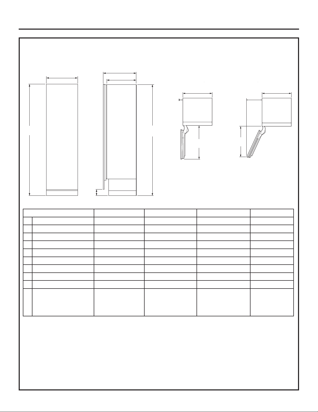
Dimensions and Clearances 6
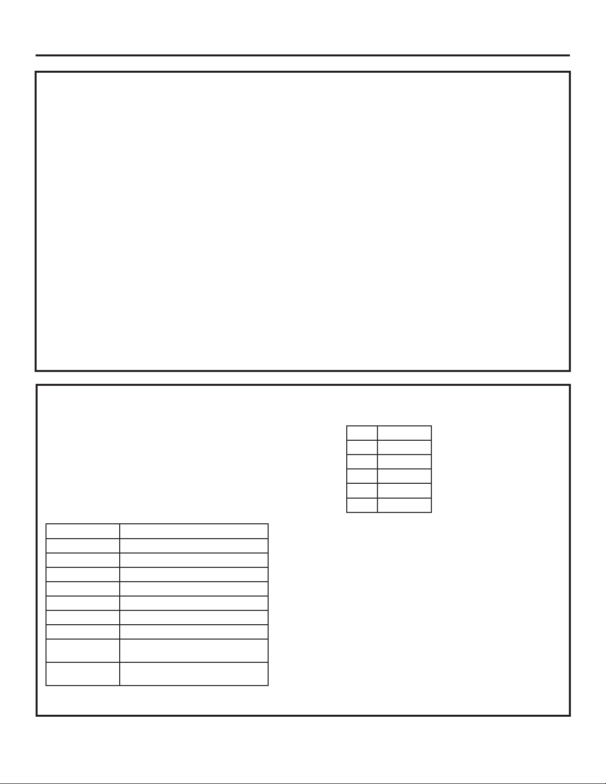
Accessories/Kits 7
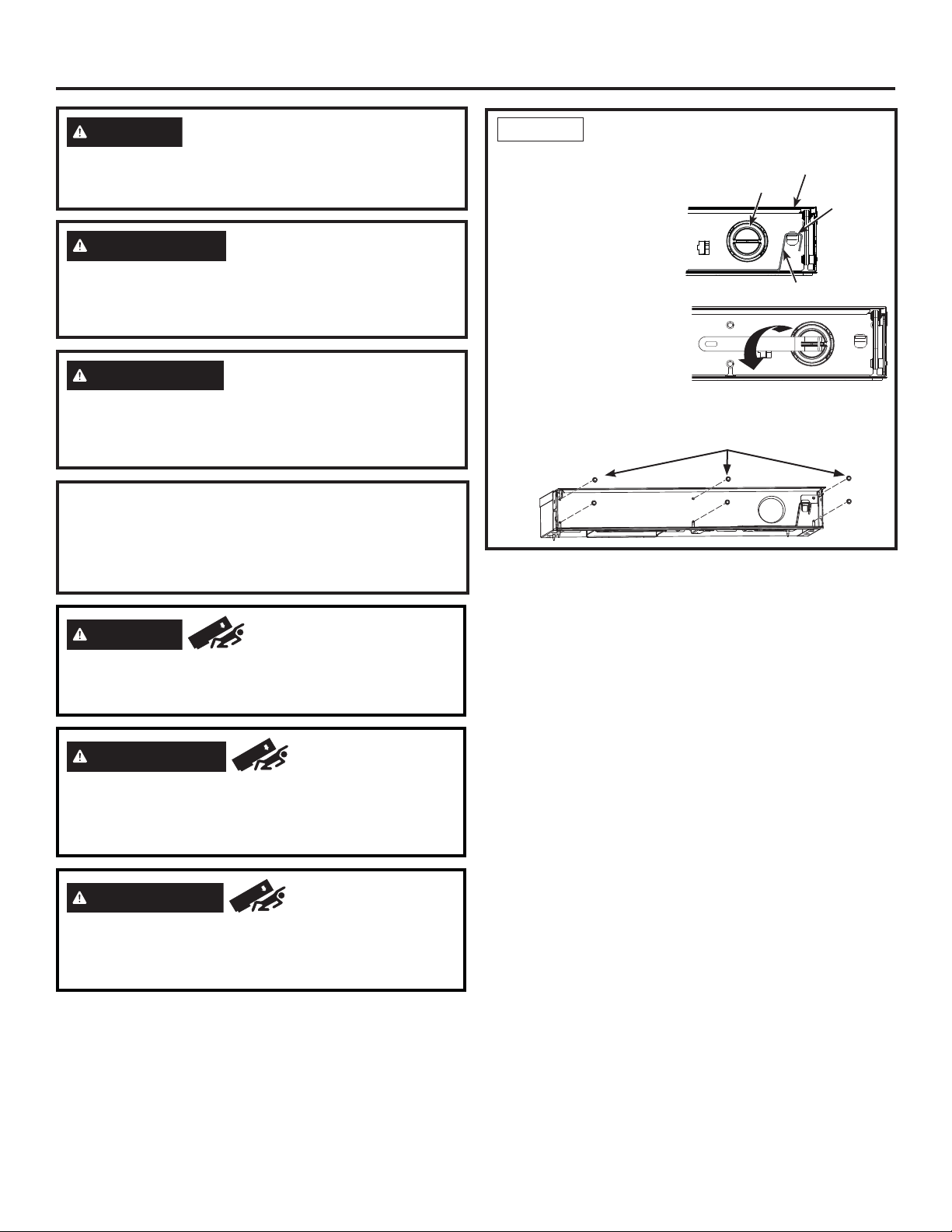
Reversing the Door Swing 8
Step 1. Remove Upper Enclosure 9
Step 2. Remove Door 10
Step 3. Move Control Assembly 11
Step 4. Move Light Switch Housing 11
Step 5. Reinstall Hinge Brackets 12
Step 6. Reinstall the Enclosure 12
Step 7. Reinstall the Front Access Cover 13
Step 8. Remove Hinges from Door 13
Step 9. Panel Brackets and Hinges 13
Step 10. Reinstall the Door 14
Instructions for Dual Integrated Installation 15
The Installation Space 16
Tools, Hardware, Materials 17
Grounding the Unit 18
Flooring 18
Step 1. Remove Packaging 18
Step 2. Install Water Line 19
Step 3. Preparing Unit for Installation 20
Step 4. Install Anti-tip Bracket 21
Step 5. Joining Dual Installed Units 22
Step 6. Connecting Water Supply 23
Step 7. Inserting/Securing into Cabinet Surround 24
Step 8. Level Unit 25
Step 9. Final External Unit Preparation 26
Step 10. Toe Kick Installation 27
Step 11. Internal Unit Preparation 27
Step 12. Start Icemaker 28
Step 13. Install AutoFill Pitcher Assembly 29
Instructions for Retro-Fit Installation 30
The Installation Space 31
Tools, Hardware, Materials 32
Grounding the Unit 32
Flooring 32
Step 1. Remove Packaging 33
Step 2. Install Water Line 34
Step 3. Preparing Unit for Installation 35
Step 4. Install Anti-tip Bracket 36
Step 5. Joining Dual Installed Units 37
Step 6. Connecting Water Supply 39
Step 7. Inserting/Securing into Cabinet Surround 40
Step 8. Level Unit 42
Step 9. Final External Unit Preparation 42
Step 10. Toe Kick Installation 44
Step 11. Internal Unit Preparation 44
Step 12. Start Icemaker 44
Step 13. Install AutoFill Pitcher Assembly 45
Instructions for Single Integrated Installation 46
The Installation Space 47
Tools, Hardware, Materials 48
Grounding the Unit 48
Flooring 48
Step 1. Remove Packaging 49
Step 2. Install Water Line 50
Step 3. Preparing Unit for Installation 51
Step 4. Install Anti-tip Bracket 51
Step 5. Connecting Water Supply 52
Step 6. Inserting/Securing into Cabinet Surround 53
Step 7. Level Unit 54
Step 8. Final External Unit Preparation 54
Step 9. Toe Kick Installation 55
Step 10. Internal Unit Preparation 55
Step 11. Start Icemaker 56
Step 12. Install AutoFill Pitcher Assembly 57
Stainless Steel Door Panel Installation 58
Step 1. Install Stainless Panel 59
Step 2. Adjust Stainless Panel 59
Step 3. If Doors Reversed Complete Steps 61
Step 4. Install Hinge Covers 61
Step 4. Install Door Trims 62
Custom Overlay Door Panel Installation 63
Custom Handle Design Guide 64
3/4” Custom Decorative Panel Dimensions 64
Step 1. Overlay Panel Prep 65
Step 2. Install Overlay Panel 66
Step 3. Adjust Overlay Panel 67
Step 4. If Doors Reversed Complete Steps 67
Step 4. Install Hinge Covers 68
Step 5. Install Door Trims 68
Para acceder al servicio local de Monogram en su área, visite monogram.com o 800.444.1845.
Para acceder al servicio de Monogram en Canadá, visite monogram.ca o 800.561.3344.
Para acceder a Piezas y Accesorios de Monogram, visite monogram.com o 800.444.1845..
Para Piezas y Accesorios de Monogram en Canadá, visite monogram.ca o 800.661.1616.
For Monogram local service in your area, visit monogram.com or call 800.444.1845.
For Monogram service in Canada, visit monogram.ca or call 800.561.3344.
For Monogram Parts and Accessories, visit monogram.com or call 800.444.1845.
For Monogram Parts and Accessories in Canada, visit monogram.ca or call 800.661.1616.
Pour joindre le service Monogram de votre région, visitez monogram.com ou 800.444.1845.
Pour le service Monogram au Canada, visitez monogram.ca ou 800.561.3344.
Pour le service des Pièces et accessoires Monogram, visitez monogram.com ou 800.444.1845.
Pour le service des Pièces et accessoires Monogram au Canada, visitez monogram.ca ou 800.661.1616.

631-1000600 Rev. 0
Design Guide
DIMENSIONS AND CLEARANCES
Dimensions in parentheses are in centimeters.
Product Clearances
These units are equipped with a 2-position door stop.
The factory set 115° door swing can be adjusted to 90°
if clearance to adjacent cabinets or walls is restricted.
For a 90° door swing, allow 5-1/8" (13.0 cm) minimum
clearance to a wall.
When installed in a corner, allow 15" (38.1 cm) for a
full 115° door swing on 18" and 24" models. Allow
16-9/16" (42.1 cm) on 30" models. Allow 19" (48.3cm)
on 36” models.
Shipping height.
The product can be adjusted to fit into a cutout that is
84” (213.36 cm). Use leveling legs and wheels for a
maximum 1” (2.54 cm) height adjustment.
Overall Dimensions
FRONT VIEW SIDE VIEW
83-3/8"
(211.77)
C
83-1/4"
(211.46)
AD
4"
(10.16)
O
TOP VIEWS
DOOR OPEN 90
DIMENSIONS BASED ON HANDLE
HEIGHT OF 2-9/16” (6.5)
ÛDOOR OPEN 115Û
S
EF
B
5-1/8"
(13.0)
Minimum
to a Wall
B
15"(38.1)
Minimum to a wall
(16-9/16"(42.1 cm)
on 30" models)
(19" (48.3 cm)
on 36" models)
Dimensions 18” Models 24” Models 30” Models 36” Models
A Overall Width - Front 17-1/2” (44.5 cm) 23-1/2” (59.7 cm) 29-1/2” (74.9 cm) 35-1/4” (89.5 cm)
B Overall Width - Rear 17-1/4” (43.8 cm) 23-1/4” (59.1 cm) 29-1/4” (74.3 cm) 35” (88.9 cm)
C Overall Depth 24-3/4” (62.9 cm) 24-3/4” (62.9 cm) 24-3/4” (62.9 cm) 24-3/4” (62.9 cm)
D Case Depth 22-1/16” (56 cm) 22-1/16” (56 cm) 22-1/16” (56 cm) 22-1/16” (56 cm)
E Door Clearance at 90° 21-1/4” (53.9 cm) 27-1/4” (62.9 cm) 33-1/4” (84.5 cm) 39-1/4 (99.7 cm)
F Door Clearance at 115° 19-1/16” (48.4 cm) 24-1/2” (62.2 cm) 29-15/16” (76.0 cm) 35-3/8 (89.9 cm)
Cutout Width 17-13/16” (45.3 cm) 23-13/16” (60.5 cm) 29-13/16” (75.7 cm) 35-13/16 (90.9 cm)
Cutout Height 84” (213.4 cm) 84” (213.4 cm) 84” (213.4 cm) 84” (213.4 cm)
Cutout Depth 25” (63.5 cm) 25” (63.5 cm) 25” (63.5 cm) 25” (63.5 cm)
Weight 370 lbs
(167.8 kg)
460 lbs (208.7 kg)
(Refrigerator)
430 lbs. (195.0 kg)
(Freezer)
495 lbs (224.5 kg)
(Refrigerator)
475 lbs. (215.5 kg)
(Freezer)
545 lbs (247.7 kg)
(Refrigerator)
530 lbs (240.9)
(Freezer)

7
31-1000600 Rev. 0
Design Guide
7KH0RQRJUDP&ROXPQVUHIULJHUDWRUVDQGIUHH]HUVFDQEHLQVWDOOHGLQPDQ\FRQ¿JXUDWLRQVZLWKGLႇHUHQWLQVWDOODWLRQ
situations. Three installation situations will be explained along with door reversal instructions and two options for door
panel installation.
Reversing the Door Swing (all installation types)
Making a refrigerator LH swing and freezer RH swing. MUST be done BEFORE the unit is removed from the ship-
ping skid.
Instructions for Dual Integrated Installation
New construction installation with 25” deep openings
Instructions for Retro Installation
Existing construction installation (existing cutouts) with 24” deep openings that are 35-1/2”, 36”, 41-1/2”, 47-1/2”
or 71-1/2” wide.
Instructions for Single Integrated Installation
New construction installation with 25” deep opening
Instructions for Stainless Steel Door Panel Installation (all installation types)
Installing Stainless Steel Door Panel Kits
Instructions for Custom Overlay Door Panel Installation (all installation types)
Installing Custom Decorative Panels
ACCESSORIES/KITS
Ŷ ZKUN+HDWHU8QL¿FDWLRQ.LW
Ŷ WX08X10006 8 Ft. Water Line
Ŷ ZKR42N 42” Trim Retro Kit
Ŷ ZKR48N 48” Trim Retro Kit
Ŷ ZKR36R 36” Trim Retro Kit
Ŷ ZKR72R 72” Trim Retro Kit
Ŷ 6WDLQOHVV6WHHO'RRU3DQHO.LWV
Ŷ 6WDLQOHVV7RH.LFNVIRU'XDO,QVWDOO
ZK1SN189NLH LH 18” Stainless Steel Door Panel
ZK1SN184NRH RH 18” Stainless Steel Door Panel
ZK1SN249NLH LH 24” Stainless Steel Door Panel
ZK1SN244NRH RH 24” Stainless Steel Door Panel
ZK1SN309NLH LH 30” Stainless Steel Door Panel
ZK1SN304NRH RH 30” Stainless Steel Door Panel
ZK1SN369RLH LH 36”Stainless Steel Door Panel
ZK1SN364RRH RH 36”Stainless Steel Door Panel
ZKSP1H1CNSS Minimalist Handle for Stainless
Steel Panels Only
ZKSP1H1PNSS Statement Handle for Stainless
Steel Panels Only
42” ZKK42P
48” ZKK48P
54” ZKK54P
60” ZKK60P
66” ZKK66R
72” ZKK72R

831-1000600 Rev. 0
Reversing the Door Swing
This step can be done for all installation types.

9
31-1000600 Rev. 0
Installation Instructions - Reversing the Door Swing
STEP 1 REMOVE UPPER
ENCLOSURE
ŶOpen the front cover of
the enclosure to 90°.
Locate filter and filter
removal tool. Filter should
be as shown.
Ŷ5RWDWH¿OWHUóWXUQ
counterclockwise (use
¿OWHUUHPRYDOWRROLI
needed).
Ŷ3XOO¿OWHUWRZDUG\RXWR
remove. NOTE: Water
system will not function
ZLWKRXW¿OWHULQSODFH
ŶRemove 6 screws securing front enclosure to top case.
WARNING Follow all steps when reversing the door
swing. Failure to follow these instructions, leaving off parts,
or overtightening screws, can lead to the door falling off and
result in injury and property damage.
ŶIf installation will require the door swing to be reversed, follow
these directions to reverse the door swing BEFORE the unit
is removed from the shipping skid.
ŶInstructions for reversing a RH swing refrigerator are shown
in the following steps.
WARNING Tip Over Hazard.
This appliance is top heavy, especially with the door open,
and must be secured to prevent tipping forward which could
result in death or serious injury.
1/4” Hex Screws
Filter Removal Tool
Filter
Mounting
Hook
Compartment Door
AVERTISSEMENT Suivez toutes les étapes pour
inverser le sens d’ouverture de porte. L’omission de suivre
ces instructions, de ne pas utiliser toutes les pièces, ou le
serrage excessif des vis, peuvent causer la chute de la porte et
occasionner des blessures ou des dommages à la propriété.
AVERTISSEMENT Risque de
basculement. Ces électroménagers sont lourds du haut,
notamment lorsqu’une porte est ouverte, de sorte qu’ils
doivent être fixés pour prévenir un basculement vers l’avant
susceptible d’occasionner des blessures graves ou la mort.
ADVERTENCIA Siga todos los pasos al invertir la
dirección de la apertura de la puerta. Si no se siguen estas
instrucciones, dejando piezas sin uso o ajustando tornillos en
exceso, esto podrá hacer que la puerta se caiga y producir
lesiones y daños sobre la propiedad.
ADVERTENCIA Riesgo de Caídas
Este electrodoméstico es inestable, especialmente cuando
una puerta se encuentre abierta, y deberá estar asegurado a
fin de evitar caídas hacia adelante que puedan resultar en la
muerte o en lesiones graves.

10 31-1000600 Rev. 0
Installation Instructions - Reversing the Door Swing
STEP 2 REMOVE DOOR
ŶOpen the door to the open position.
ŶHave a second person support the open door.
ŶRemove 2 T30 Torx screws securing the bottom hinge to the
case.
ŶRemove the 2 T30 Torx screws securing the top hinge to the
case.
ŶPlace the door on a protected work surface (to prevent
scratches), liner side down.
NOTICE: Door hinges will remain in the open position during
the door reversal procedure.
WARNING
Door Hinge Pinch
Point Hazard
Door hinges are under tension and should be left in the
open position throughout the reversal process. Closing
the hinge can lead to a finger pinch point hazard.
Screws
Screws AVERTISSEMENT
Risque de
pincement de doigts
Les charnières de porte sont sous tension et doivent être
laissées en position ouverte durant toute la procédure
d’inversion. La fermeture de la charnière peut poser un
risque de coincement de doigts.
ADVERTENCIA
Riesgo de
Lastimaduras con la Bisagra de la Puerta
Las bisagras de la puerta se encuentran bajo tensión y se
deberán dejar en la posición abierta, a través del proceso
de inversión. Cerrar la bisagra podrá producir un riesgo de
lastimadura de dedos.

11
31-1000600 Rev. 0
Installation Instructions - Reversing the Door Swing
STEP 3
MOVE CONTROL ASSEMBLY
ŶRemove upper hinge brackets by removing the T-30
Torx screws.
ŶRemove the
Phillips head
screw from the
middle of the
housing on the
hinge side.
ŶInsert a flat head screwdriver or putty knife between
the glass front and plastic side and free the control
assembly by prying the plastic pins clear of the side
bracket holes.
ŶLay the glass assembly on top of the control housing.
ŶRemove 4 screws, 2 on each end, to remove the
housing assembly using a 1/4” Hex bit.
ŶMove the housing assembly to the opposite side and
install using the 4 screws, 2 on each side.
NOTE: Make sure wires do not get pinched. On 18”
models, the red/white/black 5-pin wire connector
will need to be removed from the control board and
routed through the opposite corner bracket and
reconnected to the
control board to
prevent pinching
the wiring.
STEP 3
MOVE CONTROL ASSEMBLY
(Cont.)
ŶSnap glass assembly back onto the control housing
assembly, ensuring plastic pins snap into holes on
the side of the housing.
STEP 4 MOVE LIGHT SWITCH
HOUSING
ŶRemove front access cover from unit by removing
two 1/4” hex head screws.
ŶRemove the Philip screw first and lower hinge
brackets by removing three T-30 Torx screws.
ŶRemove screw with 1/4” hex bit driver at the bottom
corner of light switch housing.
Plastic Pins
(Both sides)
Screw
5-pin wire connector
Wires must be rerouted from one
side to the other for 18” models.
Access Cover 1/4” Hex Head
Screws
Upper Hinge
Bracket
T-30 Torx screws
Phillips Screw
T-30 Torx Screws
Phillips Screw
Light Switch

12 31-1000600 Rev. 0
Installation Instructions - Reversing the Door Swing
STEP 5 REINSTALL HINGE
BRACKETS
ŶMove top hinge bracket to bottom and bottom bracket
to top.
ŶEnsure the 2 rectangular slots of bracket are on
outside, hinge side of case.
ŶInstall both brackets with 3 T-30 Torx screws 45 in/lb
(5.1 Nm).
ŶInstall the Phillips screw.
ŶStart 2 screws in
each bracket for
hinge mounting
but do not tighten
all the way.
STEP 6 REINSTALL THE
ENCLOSURE
ŶInstall the enclosure assembly with removed six 1/4”
hex head screws.
ŶLocate blue arrow on filter. Rotate filter to align arrow
as shown.
Rectangular
Slots
Screws for
Hinge Brackets
Housing Key Holes
STEP 4 MOVE LIGHT SWITCH
HOUSING (Cont.)
ŶMove the mounting bracket to the other side of the
unit by removing two Philips screws and using them
to install the bracket in its new location.
ŶSlide housing forward and down to remove from case
and grommets on case bottom.
ŶKeeping it connected to the unit, lay housing aside.
ŶRemove 2 grommets with Phillips driver.
ŶMove grommets to the set of 2 holes on opposite
side.
ŶAlign housing key holes over grommets and then
slide back until engaged. Ensure wires do not get
pinched.
ŶInstall Phillips screw into bottom hole to hold in place.
Grommets
Mounting
Bracket and
Screws
Phillips Screw
1/4” Hex Screws

13
31-1000600 Rev. 0
Installation Instructions - Reversing the Door Swing
STEP 8 REMOVE HINGES Bottom
Hinge Cover
ŶRemove bottom hinge cover. Retain cover and
screws for reversing hinge covers during SS door or
custom overlay panel installation.
WARNING
Door Hinge Pinch
Point Hazard
Door hinges are under tension and should be left in
the open position throughout the reversal process.
Closing the hinge can lead to a finger pinch point
hazard.
STEP 6 REINSTALL THE
ENCLOSURE (Cont.)
Ŷ,QVHUW¿OWHULQWRSRVLWLRQDQGURWDWHóWXUQFORFNZLVH
XVH¿OWHUUHPRYDOWRROLIQHHGHG
Ŷ5HWXUQ¿OWHUUHPRYDOWRROWRPRXQWLQJKRRN
Ŷ
Close the compartment door.
STEP 7 REINSTALL THE FRONT
ACCESS COVER
ŶPut the access cover back onto the unit and secure
with two 1/4” hex head screws.
ŶVerify the two 1/4” hex head screws are assembled
to handle side of the products for both freezer and
fresh food columns.
1/4” Hex Screws
Access
Cover
1/4” Hex
Screws
Bottom
hinge
cover
T30 Torx
screws
AVERTISSEMENT
Risque de
pincement de doigts
Les charnières de porte sont sous tension et doivent être
laissées en position ouverte durant toute la procédure
d’inversion. La fermeture de la charnière peut poser un
risque de coincement de doigts.
ADVERTENCIA
Riesgo de
Lastimadura con la Bisagra de la Puerta
Las bisagras de la puerta se encuentran bajo tensión
y se deberán dejar en la posición abierta, a través del
proceso de inversión. Cerrar la bisagra podrá producir un
riesgo de lastimadura de dedos.
STEP 9 REMOVE HINGES FROM
DOOR
ŶRemove 3 screws securing each hinge from the top
and bottom of the door and one screw securing the
support bracket to the door (T-30 Torx)
Hinge
Support
Bracket
Shims

14 31-1000600 Rev. 0
Installation Instructions - Reversing the Door Swing
STEP 10 PANEL BRACKETS AND
HINGES
ŶRemove panel brackets on each end of the door by
removing the T30 Torx screws.
ŶSlide same bracket on each end to other side of door
and re-install brackets to door.
ŶInstall hinges to door ensuring that 2 shims for 18”,
24” and 30” are between hinge L-bracket and door.
Install hinges to door ensuring that 1 shim for 36” is
between hinge L-bracket and door. Install with 3 T-30
Torx screws 45 in-lb (5.1 Nm).
NOTE: Ensure L-bracket remains attached to hinge
and is on the outer side of the door. Hinge is on the
inner door side.
REMINDER: Hinges have to move from top to bottom
and bottom to top.
ŶInstall support bracket screw through both support
bracket and panel bracket.
STEP 11 REINSTALL THE DOOR
ŶEnsure 2 hinge screws are started but not tightened
in hinge brackets on case.
ŶWith 2nd person, hold door with hinges near correct
position.
ŶInstall top hinges with key hole over screws and slide
bracket.
ŶRepeat on bottom.
NOTE: Ensure 2 tabs on hinges are inserted into
the rectangular slots on outside of hinge brackets
BEFORE tightening screws.
ŶTighten bottom screws 45 in/lb (5.1 Nm).
ŶTighten top screws 45 in/lb (5.1 Nm).
ŶCarefully ensure door closes correctly and gasket
aligns with case.
WARNING Follow all steps when reversing
the door swing. Failure to follow these instructions,
leaving off parts, or overtightening screws, can
lead to the door falling off and result in injury and
property damage.
Hinge
Support
Bracket
Shim(s)
Tabs in rectangular slots
Key hole slot over screws
STEP 9 REMOVE HINGES FROM
DOOR
ŶMove the hinge assembly to
the opposite end of the door
- top hinge to the bottom and
bottom hinge to the top. Hinge,
L-bracket already attached to
hinge, and support bracket will
all move together.
ŶOn 18”, 24” and 30” Products,
two shims and on 36” product
one shim between the hinge
bracket and door will be moved
to the other side. Save for
installing the hinge.
AVERTISSEMENT Suivez toutes les étapes pour
inverser le sens d’ouverture de porte. L’omission de suivre ces
instructions, de ne pas utiliser toutes les pièces, ou le serrage
excessif des vis, peuvent causer la chute de la porte et
occasionner des blessures ou des dommages à la propriété.
ADVERTENCIA Siga todos los pasos al invertir
la dirección de apertura de la puerta. Si no se siguen
estas instrucciones, dejando piezas sin uso o ajustando
tornillos en exceso, esto podrá hacer que la puerta se
caiga y producir lesiones y daños sobre la propiedad.

15
31-1000600 Rev. 0
Instructions for Dual Integrated Installation
New construction installation with 25” deep openings

16 31-1000600 Rev. 0
Design Guide - Dual Integrated Installation
DUAL INTEGRATED INSTALLATION SPACE
Dimensions in parentheses are in centimeters.
LH RH ENCLOSURE
WIDTH AB C D E FGH
18 36 53 1/2 4 1/8 3 1/2 7 1/2 2 26 9 36 9
135.9 10.5 8.9 19.1 5.1 66.0 22.9 91.4 22.9
830 47 1/2 4 1/8 3 1/2 7 1/2 2 22 1/8 5 28 6 1/4
120.7 10.5 8.9 19.1 5.1 56.2 12.7 71.1 15.9
18 24 41 1/2 4 1/8 3 1/2 7 1/2 2 22 1/8 5 27 1/4 4
105.4 10.5 8.9 19.1 5.1 56.2 12.7 69.2 10.2
24 36 59 1/2 4 3/8 5 9 1/2 4 32 9 42 9
151.1 11.1 12.7 24.1 10.2 81.3 22.9 106.7 22.9
24 30 53 1/2 4 3/8 5 9 1/2 4 28 1/8 5 34 6 1/4
135.9 11.1 12.7 24.1 10.2 71.4 12.7 86.4 15.9
24 24 47 1/2 4 3/8 5 9 1/2 4 28 1/8 5 33 1/4 4
120.7 11.1 12.7 24.1 10.2 71.4 12.7 84.5 10.2
30 36 65 1/2 4 3/8 5 9 1/2 4 38 9 48 9
166.4 11.1 12.7 24.1 10.2 96.5 22.9 121.9 22.9
30 30 59 1/2 4 3/8 5 9 1/2 4 34 1/8 5 40 6 1/4
151.1 11.1 12.7 24.1 10.2 86.7 12.7 101.6 15.9
36 36 71 1/2 8 9 18 9 44 9 54 9
181.6 20.3 22.9 45.7 22.9 111.8 22.9 137.2 22.9
INCHES / CENTIMETERS
84" (213.4)
2 1/2" (6.4)
25" (63.5)
AB
CD
Enclosure Width
(See Chart)
Finished
Return
ELECTRIC WATER
6" (15.2)

17
31-1000600 Rev. 0
Design Guide - Dual Integrated Installation
DUAL INTEGRATED INSTALLATION SPACE
Water And Electrical Locations
Electrical and water supply must be located as shown.
The Cutout Depth Must Be 25”
Cutout is based on installation of 2 products with a left-
and-right hand door swing.
Heater Unification Kit ZKUN required.
Product Clearances
These units are equipped with a 2-position door stop.
The factory set 115° door swing can be adjusted to 90°
if clearance to adjacent cabinets or walls is restricted.
For a 90° door swing, allow 4” (10.2 cm) minimum
clearance to a wall.
When installed in a corner, allow 15” (38.1 cm) for a full
115° door swing on 18” and 24” models. Allow 16.5”
(41.9 cm) on 30” models.
Additional Specifications
• A separate 115 volt 60Hz., 15 or 20 amp power supply
is recommended for each product. An individual
properly grounded branch circuit or circuit breaker is
recommended. Install a properly grounded 3-prong
electrical receptacle recessed into the back wall.
Electrical must be located on rear wall as shown.
• Water line must be located on the back wall as shown.
The water line should be 1/4” O.D. copper tubing or
QuickConnect™kit (WX08X10006) between the cold
water line and water connection location, long enough
to extend to the front of the unit (8’ [2.4m]). Installation
of an easily accessible shut-off valve in the water line
is required.
• A minimum of 3-1/2” finished return matching cabinet
exterior is recommended on interior on all sides and
top at front of opening.
TOOLS AND MATERIALS REQUIRED
• Metal shears
• #1, #2 Phillips screwdriver
• Flathead screwdriver
• Putty knife
• Measuring tape
• Drill and 1/16”, 5/64”, 3/16”, 1/2” bits
• 5/32” concrete bit (if installing anti-tip into concrete)
• 1/4”, 3/8”, 7/16” driver/socket
• 7/16” open wrench
• T10, T20, T30 driver/bit
• 1/8”, 1/4” hex driver (allen wrench)
• Level
• Water shut-off valves (optional but recommended)
• 8’ waterline (one per unit requiring water hookup)
• Masking tape
• Rubbing alcohol
• Adjustable wrench
• Center punch
• Heater Unification Kit (ZKUN)
• Stainless Steel Door Kits (if applicable)
• Custom panels for doors (if applicable)
• Handle Kits (if applicable)
• Small Ratchet
REFRIGERATOR/FREEZER LOCATION
ŶDo not install the refrigerator/freezer where the tem-
perature will go below 55°F (13°C). It will not run
often enough to maintain proper temperatures.
ŶDo not install the refrigerator/freezer where
temperatures will go above 100°F (37°C). It will not
perform properly.
ŶDo not install the refrigerator/freezer in a location
exposed to water (rain, etc.) or direct sunlight.
Ŷ Install it on a floor strong enough to support it fully
loaded.
HARDWARE SUPPLIED (per unit)
• Water Filter Bypass Plug (if equipped)
• Air filter (if equipped)
• Anti-Tip bracket (qty 2 for 36”)
• 3 Lag screws (qty 6 for 36”)
• 3 Tapcon screws (qty 6 for 36”)
• 3 Toggles with bolts (qty 6 for 36”)
• Panel installation templates
• 2 Door trims
• 2 Door panel brackets
• Set screws
• #6 Phillips head wood screws
• Door Bracket Cover Top
• T30 screws
• 1 Hinge limiter pin
• Center door panel bracket
• Hi-Lo screw and square washer
• Stainless Toe Kick
• Painted access cover screws
• T10 screw

18 31-1000600 Rev. 0
Installation Instructions - Dual Integrated Installation
FLOORING
For proper installation, this product must be placed
on a level surface of hard material that is at the same
height as the rest of the flooring. This surface should
be strong enough to support a fully loaded refrigerator
or freezer, or approximately 1,200 lbs. per unit.
NOTE: Protect the finish of the flooring.
NOTE: Not recommended for installation on carpeted
flooring.
GROUNDING THE UNIT
The power cord of this appliance is equipped with a
3-prong (grounding) plug which mates with a standard
3-prong (grounding) wall receptacle to
minimize the possibility of electric shock
hazard from this appliance.
Have the wall outlet and circuit checked
by a qualified electrician to make sure the
outlet is properly grounded.
Where a standard 2-prong wall outlet is encountered, it
is your personal responsibility and obligation to have it
replaced with a properly grounded 3-prong wall outlet.
DO NOT, UNDER ANY CIRCUMSTANCES, CUT OR
REMOVE THE THIRD (GROUND) PRONG
FROM THE POWER CORD.
DO NOT USE AN ADAPTER PLUG TO CONNECT
THE REFRIGERATOR TO A 2-PRONG OUTLET.
DO NOT USE AN EXTENSION CORD WITH THIS
APPLIANCE.
WARNING Electrical Shock
Hazard. Failure to follow these instructions can
result in death, fire, or electrical shock.
STEP 1 REMOVE PACKAGING
ŶRemove outer carton and external packing from units.
ŶInspect for damage.
ŶIf installation will require the door
swing to be reversed, follow the
instructions in Reversing the
Door Swing section to reverse
the door swing BEFORE the unit
is removed from the shipping
skid.
ŶEnsure the flooring that the units
are set is clean/free of debris that could be collected
on to, or pinched in front of the wheels and damaging
the floor. Additionally, it is recommended that the
floor be protected with a plastic covering through out
the installation process.
ŶRemove hardware kit from top drawer.
ŶIf installation requires a 90°door opening, the hinge
limiter pin must be installed in the top hinge BEFORE
the unit is removed from the shipping skid. Pin is
located in the hardware kit.
- Open the door approximately 45°, but no wider than
90°, to expose the hole in the back hinge bracket
and install the limiting pin. Pin must be fully seated
in the bracket or the door will not close properly.
Top
Hinge
WARNING Tip Over Hazard. This
appliance is top heavy. Use extreme caution with
moving to prevent tipping over which could result in
death or serious injury.
KIT ZKUN PARTS SUPPLIED:
Adhesive Heater
Transformer
Front Mullion
Trim Bracket
Top Unification Bracket
Bottom Front Unification Bracket
3 1/4” Hex Head 8-18 5/8” Long Screws
5 1/4” Hex Head 8-32 5/8” Long Screws
5 3/8” Hex Head 1/4-20 1/2” Long Screws
4 wire clips
Tools and Materials Required:
1/4” and 3/8” driver / sockets
#2 Phillips screwdriver
Rubbing alcohol
AVERTISSEMENT Risque d’électrocution
Le non-respect de ces instructions peut occasionner un
décès, un incendie ou un choc électrique
ADVERTENCIA Riesgo de Descarga
Si no se siguen estas instrucciones, se podrá producir
la muerte, incendios o descargas eléctricas.
AVERTISSEMENT
Risque de
basculement.
Cet électroménager est lourd du haut.
Usez d’extrême prudence en le déplaçant afin de prévenir
un basculement susceptible d’occasionner des blessures
graves ou la mort.
ADVERTENCIA Riesgo de Caída.
Este electrodoméstico es inestable. Tenga extremo
cuidado al moverlo, a fin de evitar caídas hacia adelante
que podrían resultar en la muerte o lesiones graves.

19
31-1000600 Rev. 0
Installation Instructions - Dual Integrated Installation
STEP 1 REMOVE PACKAGING
ŶRemove front access cover from unit by removing two 1/4”
hex head screws. (Some models have access cover in a
box on the left side of the cabinet.) Place the cover and
screws to the side for future installation.
ŶRemove three 3/8” drive screws and two 7/16” drive
screws from each side of the unit to release it from the
shipping skid. Tip the unit from the side enough to remove
the shipping material from under the unit, but above the
shipping skid (both sides)
ŶCAREFULLY roll the unit off the back side of the shipping
skid.
ŶHandle from side only with a hand truck.
Shipping
Bracket
7/16” Drive
Screws
3/8” Drive
Screws
1/4” Hex Head
Screws
STEP 2 INSTALL WATER LINE
Shut off the main water supply.
Turn on the nearest faucet long enough to clear the line of
water.
ŶInstall a shut-off valve between the water valve and cold
water pipe in a basement or cabinet. The shut-off valve
should be located where it will be easily accessible.
ŶTurn on the main water supply and flush debris. Run about
a quart of water through the tubing into a bucket. Shut off
water supply at the shut-off valve.
NOTE: Saddle type shut-off valves are included in many
water supply kits. Before purchasing, make sure a saddle
type valve complies with your local plumbing codes.
NOTE: Commonwealth of Massachusetts Plumbing
Codes 248CMR shall be adhered to. Saddle
valves are illegal and use is not permitted in
Massachusetts. Consult with your licensed plumber.
ŶRoute 1/4” OD copper or SmartConnect™(WX08X10006)
plastic tubing between house cold water line and the water
connection location at the front of the unit.
SmartConnect™Refrigerator Tubing Kits are available.
One 8’ (2.4m) water line (WX08X10006) is needed for
each unit. The waterline(s) will be taped to the floor using
masking tape after anti-tip bracket installation.
ŶTubing should be long enough to extend to the front of the
unit. Allow enough tubing to accommodate bend leading
into the water line connection. Unit must be tipped on its
side to route waterline underneath and to the front of the
appliance.
NOTE: The only GE Appliances approved plastic tubing is
supplied in the SmartConnect™Refrigerator Tubing kits. Do
not use any other plastic water supply line because the line is
under pressure at all times. Other types of plastic may crack
or rupture with age and cause water damage to your home.
WARNING Connect to potable water supply
only. A cold water supply is required for automatic
icemaker operation. The water pressure must be
between 40 and 120 psi (275-827 kilopascals).
WARNING ELECTRIC SHOCK HAZARD
Attach tubing clamp using existing hole only. DO
NOT drill into the refrigerator.
AVERTISSEMENT Raccordez l’appareil à une
alimentation d’eau potable seulement. Une alimentation
d’eau froide est requise pour faire fonctionner la machine à
glaçons et le pichet à remplissage automatique. La pression
d’eau doit se situer entre 40 et 120 psi. (275 à 827 kPa).
AVERTISSEMENT
RISQUE DE DÉCHARGE
ÉLECTRIQUE
Fixez le collier de serrage dans le trou présent seulement.
NE PERCEZ PAS dans le réfrigérateur.
ADVERTENCIA Realice la conexión a un suministro
de agua potable únicamente. Se requiere un suministro de
agua fría para el funcionamiento de la máquina de hielos
automática y de la jarra de llenado automático. La presión del
agua deberá estar entre 40 y 120 p.s.i. (275 – 827 kPa).
ADVERTENCIA
PELIGRO DE DESCARGA
ELÉCTRICA
Adhiera la abrazadera de la tubería usando el agujero
existente únicamente. NO perfore el refrigerador.

20 31-1000600 Rev. 0
Installation Instructions - Dual Integrated Installation
STEP 3 PREPARING UNIT FOR
INSTALLATION
ŶInstall the transformer into the case top assembly:
1. Remove cover top by removing eight #8 hex screws
and keep aside for assembling back the cover top.
2. Place the transformer into the case top provided in
ZKUN kit and secure it with the existing (1/4”) hex
screws to left front of case top.
3. Connect the 2 pin transformer connector to the
heater connector and 3 pin connector to panel
control, make sure locking tabs are engaged.
4. NOTE: Verify the master switch is on.
5. Assemble the cover top with screws save from
previous step.
STEP 3 PREPARING UNIT FOR
INSTALLATION
ŶUnpack the heater Unification Kit (ZKUN) and make
sure all of the components on the list are included.
NOTE: Ensure the heater connector cord is toward the
top of the unit when installed.
ŶPlace the right hand unit in front of the installation
opening in a way that the unit is in front of the
intended installed location.
ŶInstall adhesive heater on the outside of the unit to
the left side of the case. Install heater 4” below the
case top. Heater should be centered front to back on
the metal case. Clips
Adhesive
Heater
WARNING Electrical Shock
Hazard. To avoid the risk of electric shock, make
sure the power cord is not plugged into the wall outlet.
4”
STEP 3 PREPARING UNIT FOR
INSTALLATION (Cont.)
Enclosure assembly upper
is hidden for clarity.
Do NOT
Remove Wire
Standoff
2 Pin
Connector
to Heater
Connector
3 Pin
Connector
Transformer
Master Switch
#8 Hex
Screws Cover Top
AVERTISSEMENT Risque
d’électrocution. Pour prévenir le risque
d’électrocution, assurez-vous que le cordon électrique
n’est pas branché dans la prise murale.
ADVERTENCIA Riesgo de Descarga
Si no se siguen estas instrucciones, se podrá producir
la muerte, incendios o descargas eléctricas.
Table of contents
Other Monogram Freezer manuals
Popular Freezer manuals by other brands

McCall
McCall LTA-20-FRE Specifications

Whirlpool
Whirlpool Freezer user manual

Tricity Bendix
Tricity Bendix TB 17 TF Operating & installation instructions

emerio
emerio CFR-126353 instruction manual

SPX
SPX Cooling Tower Marley NC Class Specifications

Vinotemp
Vinotemp WINE-MATE WM-2500SSWWC Installation, operation & care manual