Perlick FR24 Series User manual

INSTALLATION AND OPERATION INSTRUCTIONS
GLASS FROSTERS
Table of Contents
Cabinet Specifications ......................................... 2
Installing
Uncrating and Inspection ............................... 3
Plumbing ........................................................ 3
Electrical ......................................................... 3
Installing Shelves............................................ 3
Installing Casters or LegsCasters .................. 3
Placing The Cabinet ....................................... 3
Sealing the Floor ............................................ 3
Defrost System..................................................... 4
Temperature Control............................................. 4
Cleaning ............................................................... 5
Cleaning Stainless Steel/Avoiding Corrosion....... 5
Replacement Parts............................................6/7
Wiring Diagram..................................................... 8
8300 West Good Hope Road • Milwaukee, WI 53223 • Phone 414-353-7060 • Fax 414-353-7069
c
UL
®�
C
L
A
S
S
I
F
I
E
D
SANITATION
NSFI STANDARD NO 7
UL
®�
C
L
A
S
S
I
F
I
E
D
SANITATION
NSFI NO 7-1990
UL
®�
C
L
A
S
S
I
F
I
E
D
SANITATION
CLASSIFIED TO
NSFI NO 7-1990
IMPORTANT INFORMATION
This manual has been prepared to assist you in the
installation of your Glass Froster and to acquaint you
with its operation and maintenance.
We dedicate considerable time to ensure that our
products provide the highest level of customer
satisfaction. If, however service is required, call
Perlick at 1-800-777-7267 or your dealer who can
provide you with a list of qualified service agents.
For your own protection, never return merchandise
for credit without our approval.
We thank you for selecting a Perlick product
and assure you of our continuing interest in
your satisfaction.
IMPORTANT WARRANTY INFORMATION
To register your product, visit our web site at
(www.perlick.com). Click on “Commercial”, then
“Service”. You will see the link to “Warranty
Registration Form”. You must complete and submit
this form or the installation date will revert back to
the ship Date.
MODEL NOS.
FR24 Series
FR36 Series
FR48 Series
FR60 Series
Form No. Z2296
Rev. 12.05.09

2
Perlick is committed to continuous improvement. Therefore, we reserve the right to change specifications without prior notice.
Installation and Operating Instructions
Sizes and Specifications, Glass Frosters
Form No. Z2296
Rev. 12.05.09
Job ___________________________
Area __________________________
Item No. _______________________
Model No. _____________________
LENGTH (mm) 24” (610) 36” (915) 48” (1219) 60” (1524)
INTERIOR CU. FT. (m3) 3.75 (0.10) 7.83 (0.22) 11.68 (0.33) 15.53 (0.44)
PLATE CAPACITY†135 Plates 215 Plates 300 Plates 400 Plates
GLASS CAPACITY†
(w/2 Optional Shelves) 90 Glasses 142 Glasses 214 Glasses 286 Glasses
WITH OPTIONAL THIRD SHELF N/A 172 Glasses 273 Glasses 363 Glasses
CONDENSING UNIT H.P. 1/31/31/31/3
AMPS 5.8 6.8 6.2 7.1
SHIP WT lbs. (kg) 190 (86) 245 (111) 265 (120) 300 (136)
INTERIOR All models have stainless steel walls and floor.
EXTERIOR Choice of black, stainless steel and all stainless.
Black Option: Front and ends are black vinyl coated steel, back and bottom are galvanized.
Stainless Steel Option: Front and ends are stainless steel, back and bottom are galvanized.
All Stainless Option: Front, ends, back and bottom are all stainless steel.
DOORS (Sliding) Stainless steel top and bottom pans. Die cast handle.
ELECTRICAL 115V, 60 Hz., 1 Phase. Furnished with 6 foot rubber plug-in cord (115V model only). Also available in
230V, 50Hz., 1 Phase AC. carries marking of conformity.
PLUMBING None required. Moisture drains to self-evaporating condensing pan in machinery compartment.
INSULATION 2 inch foamed-in-place polyurethane insulation.
TEMPERATURE RANGE Adjustable from -10° to +10° F.
REFRIGERATION R134a expansion valve system with hermetic condensing unit. Pulls out for service and cleaning.
VENTILATION 2’ model is front vented, all other models require 2” clearance from wall either on left end or back of
cabinet for proper air flow.
DEFROST SYSTEM Solid-state, push-button defrost system, manually initiated at end of each day, automatically termi-
nates after six hours. Evaporator automatically defrosts every 4 hours for approximately 20 minutes
(time/temperature terminated).
OPTIONAL ACCESSORIES • Additional set of nesting shelves w/ brackets • Set of 4 casters w/ brakes • Interior light
• Set of 4 adjustable legs • 2’, 3’, 4’ and 5’ Bottle rail (field installed) • Roller basket shelving
† Capacity calculations based on use of 3” dia. glass and 91⁄2” dia. x 1⁄2” thick plate.
24” [610]
9 5/8” [244]
8 7/8” [225]
OPTIONAL
FIELD
INSTALLED
SHELF
LOCATION
FACTORY
INSTALLED
SHELF
LOCATION
24” [610]
11 5/8”
[296] 2”
[51]
2”
[51]
19 1/4”
[489]
INSIDE
34 1/8”
[867]
5 3/4”
[146]
5 3/4”
[146]
6 5/8”
[169]
2”
[51]
2”
[51]
FRONT VIEW
24” CABINET
END VIEW
24” CABINET
c
UL
®�
C
L
A
S
S
I
F
I
E
D
SANITATION
NSFI STANDARD NO 7
UL
®�
C
L
A
S
S
I
F
I
E
D
SANITATION
NSFI NO 7-1990
UL
®�
C
L
A
S
S
I
F
I
E
D
SANITATION
CLASSIFIED TO
NSFI NO 7-1990
MODELS FR24 FR36 FR48 FR60
11 5/8”
[295]
2” [50]
34”
[864]
6 7/8”
[175]
7”
[178]
2” [50] 2” [50] 2” [50]
24” [610]
OPTIONAL
SHELF
FRONT VIEW
36”, 48”, 60” CABINET
END VIEW
36”, 48”, 60” CABINET
17 3/16”
[437]
HOUSING
STEP
27 7/8”
[708]
INSIDE
36” [914]
48” [1219]
60” [1524]
13 7/8” [352]
TOP SHELF
7” [178]
CENTER SHELF
7” [178]
BOTTOM SHELF

3
Perlick is committed to continuous improvement. Therefore, we reserve the right to change specifications without prior notice.
Preparing the Cabinet – Glass Frosters
Uncrating and Inspection
Remove all crating material before operating.
Carefully inspect cabinet for hidden damage.
If damage is discovered, file your claim immediately
with the transport company. Perlick is not
responsible for damage in transit.
Plumbing
No plumbing connections are required. Condensate
from the cooling coil is automatically evaporated
through a condensate pan located in the
condensing unit section.
Electrical
The cabinet must be connected to a separately
fused power source (see Electrical Specification
Plate) and grounded in accordance with National
and Local Electrical Codes.
CAUTION: Do not attempt to operate the equip-
ment on any other power source than that listed
on the Electrical Specification Plate.
Installing Shelves (when provided)
The front and rear horizontal shelf brackets have
been factory installed for a 2 shelf kit glass froster.
Installing Casters or Legs (optional)
Attach casters or legs to the cabinet bottom in
holes provided. Use the supplied 1⁄4”–20 hex head
self-tapping machine screws. If unit is tipped on its
back for an extended period of time, wait 24 hours
after the unit is uprighted to plug the unit in.
Placing the Cabinet
To assure maximum performance, fresh air must
be allowed to circulate through the machinery
compartment. It is important to allow at least two
inches of clearance at the back or left end of the
cabinet. Do not place anything in front of the
cabinet that would obstruct air flow at these grilles.
Do not place the unit in an unventillated small
room.
CAUTION:
Removing the factory installed back clearance
spacers without providing proper left side grill
clearance for compressor air flow will void the
warranty.
Cabinet should be leveled.
For sanitation purposes, it may be necessary to
seal the base of the cabinet to the floor. This
can be accomplished by laying a bead of silicone
sealant along the base of the cabinet as shown
by the figure below.
BEAD SILICON
SEALER (RTV)
FLOOR
CABINET
Form No. Z2296
Rev. 12.05.09

4
Perlick is committed to continuous improvement. Therefore, we reserve the right to change specifications without prior notice.
Operation Instructions – Glass Frosters
Defrost System
This system consists of a six-hour, as well as a four
hour defrost cycle. The six hour defrost cycle is
manually activated and automatically terminated,
while the four hour cycle is completely automatic.
The Six Hour Solid-State Defrost Timer
This timer shuts off the power to the condensing
unit, door frame heater, evaporator heater, and the
automatic four hour defrost timer, while it supplies
power to the evaporator fan.
To activate the six hour defrost system, depress
the defrost switch located on the front grill of the
cabinet. An amber light will illuminate and the
defrost cycle will begin. When the defrost cycle
ends, the light goes off and the cabinet resumes
normal operation. To manually cancel the defrost
cycle, momentarily turn off the electricity to the
machine.
The Four Hour Defrost Timer
This timer ensures that frost will not buildup on the
evaporator coil. Every four hours it shuts down the
condensing unit and evaporator fan and supplies
power to the defrost element clamped to the bot-
tom of the evaporator. The defrost cycle lasts for
approximately 20.
During normal operation it is recommended that
the doors are not left open to prevent excessive
frost buildup on the coil.
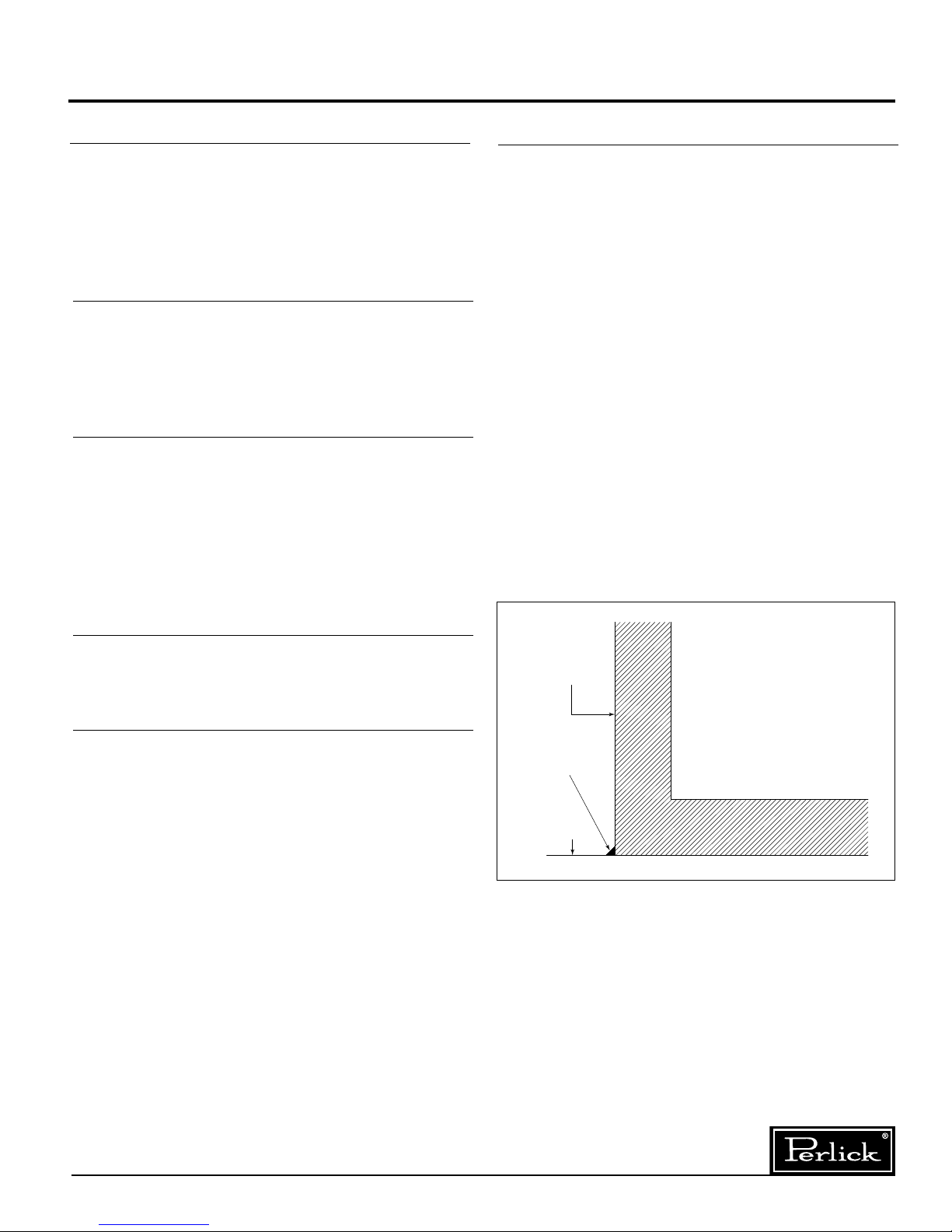
Temperature Control
An adjustable temperature control is located inside
the froster on the evaporator fan panel assembly.
Approximate temperature operating range: minus
15° F. minimum and plus 10° F. maximum. Make
adjustments as shown to attain the desired
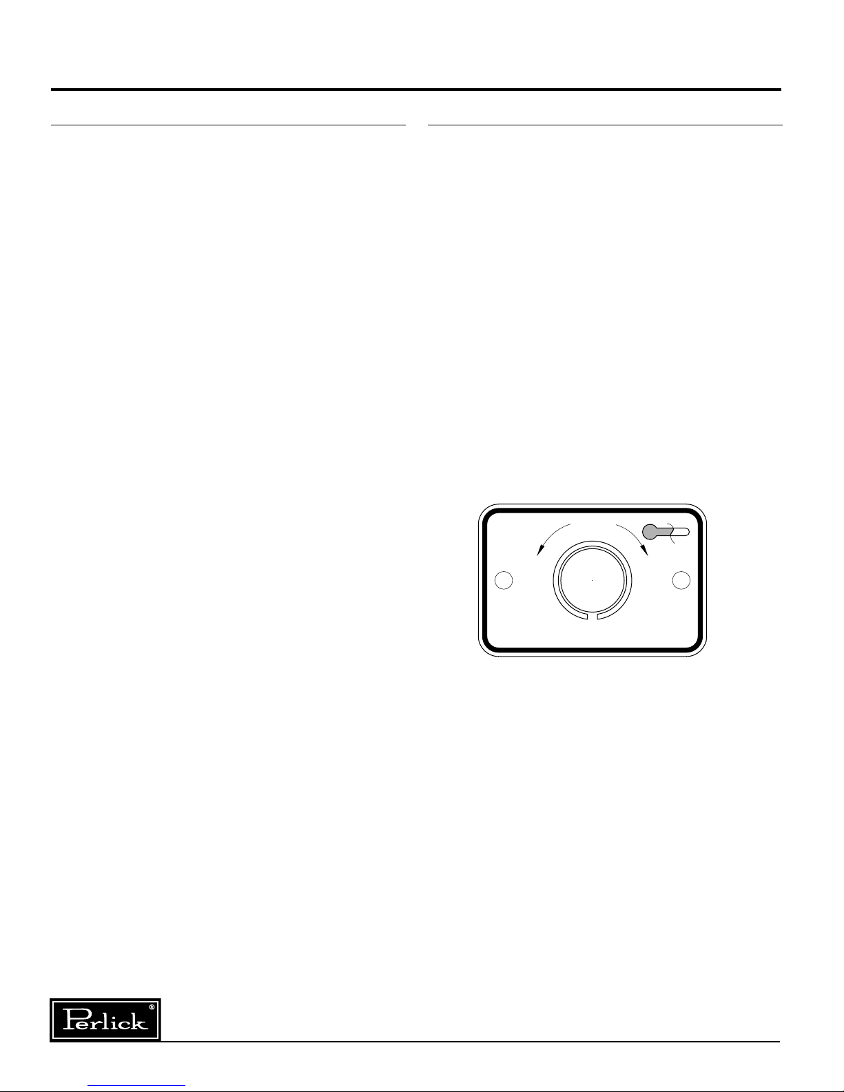
temperature.
■Colder Temperatures: Turn the adjusting
screw clockwise (to the right).
■Warmer Temperatures: Turn the adjusting
screw counterclockwise (to the left).
■Temperature Control “OFF”: Turn the
adjusting screw completely counterclock-
wise to the “O” position until a click is
noted.
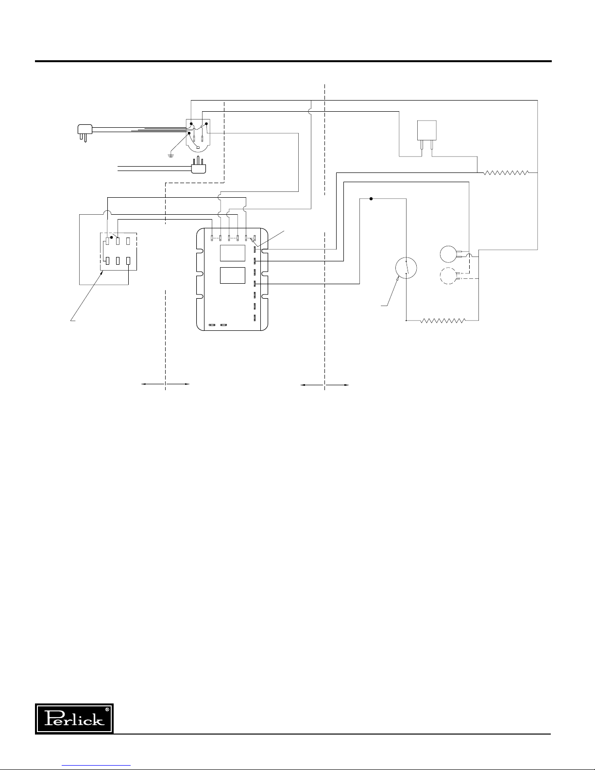
The condenser fan motor turns off and on with
the compressor. The evaporator fan motor runs
continuously, except during the 20 minute
period of the four-hour defrost.
NORMAL
05
4
6
1
9
2
8
3
7
WARMER
COOLER
CONDENSING UNIT
Form No. Z2296
Rev. 12.05.09

5
Perlick is committed to continuous improvement. Therefore, we reserve the right to change specifications without prior notice.
Cleaning Instructions – Glass Frosters
Avoiding Stainless Steel Corrosion
Corrosion can be prevented by following product cautions, cleaning instructions and avoiding use of cer-
tain chemicals or objects which will cause stainless steel corrosion.
STAINLESS STEEL ENEMY
■Steel wool or steel scouring pads
■Cherry/Orange/Olive juice
■Chlorine Bleach
■Sharp Objects
Cleaning the Condenser:
■The condenser (located behind the front
grille) should be inspected every 30 days,
and cleaned, if necessary. Failure to keep
the condenser clean will cause a loss in
condensing unit efficiency, or compressor
failure.
Cleaning the Doors:
■Doors should be periodically removed from the
cabinet and inspected for a buildup of foreign
materials, such as syrups, beer, etc. Buildups
on the underside of the doors, along with the
cabinet breaker strips on which they ride, will
cause them to bind, and therefore, not function
as designed. If dirty, these surfaces should be
cleaned with a mild detergent and water then
coated with a silicone lubricating material.
Aerosol silicone sprays can be obtained locally
at most department or automotive stores.
To remove doors:
■With door closed, lift it upward by its handle and
slide forward until door clears the cabinet top.
Use the reverse procedure to reinstall the doors.
Cleaning the Cabinet:
■Use a damp cloth with a mild detergent and
water to clean the inside and outside of the
cabinet. Dry thoroughly. Do not allow cleaning
agents or large amounts of water to go down
the drain. Use an acceptable stainless steel
polish to clean all stainless steel surfaces.
Never use steel wool or scouring pads to clean
stainless steel.
Form No. Z2296
Rev. 12.05.09

Replacement Parts – Glass Frosters
6
Perlick is committed to continuous improvement. Therefore, we reserve the right to change specifications without prior notice.
19
13
4
18
9
20
5
7
30
29
8
28
6
10
15
12
3
23
22
17
26
25
27
1
11
2
16
14
21
24
Form No. Z2296
Rev. 12.05.09
■Service should be done by a qualified
refrigeration technician.
■Disconnect all power before servicing
the cabinet.
CAUTION

7
Perlick is committed to continuous improvement. Therefore, we reserve the right to change specifications without prior notice.
Replacement Parts – Glass Frosters
MODEL NOS. FR24 FR36 FR48 FR60
Item Description Part Numbers
1 Complete condensing unit C22646A C22646A C22646A C22646A
2 Replacement compressor, R134a 513200003 513200003 513200003 513200003
Condensing unit fan motor assy. 515315009 515315009 515315009 515315009
Terminal Board 519100088 519100088 519100088 519100088
Overload Protector US-PB12HBX1 US-PB12HBX1 US-PB12HBX1 US-PB12HBX1
Relay US-PB12HBX1 US-PB12HBX1 US-PB12HBX1 US-PB12HBX1
Start capacitor US-PB12HBX1 US-PB12HBX1 US-PB12HBX1 US-PB12HBX1
3 Condensate pan 64537 64626-1 64626-1 64626-1
4 Expansion valve 63549 63549 63549 63549
5 Evaporator fan motor(s) C15239A C15239A C15239A C15239A
6 Evaporator fan motor bracket 65671-1 65671-1 60988-1 60988-1
7 Evaporator fan motor blade 63461 63461 63461 63461
8 Evaporator fan guard 65666 65666 65666 65666
9 Evaporator coil 64785-1EP C17511-1EP C17511-1EP C17511-2EP
10 Evaporator defrost heater C25655-1 65045-1 65045-1 61900
11 Temperature control 61282 61282 65290 65290
12 Solid state defrost timer 57466 57466 57466 57466
13 Defrost limit switch 57676 57676 57676 57676
14 Rocker switch with pilot C31659 C31659 C31659 C31659
15 Compressor side shelf N/A 64810-1 64810-1 64810-1
16 Front grille 66498-2A 65662-2A 65662-2A 65662-2A
17 Rear grille/panel 66498-1 65662-3 65662-3 65662-3
18 Top assemby RT-SL2 RT-SL2 RT-SL2 RT-SL2
19 Top wiper gasket 63671-24 63671-36 63671-48 63671-60
20 Door assembly RD-SL2 RD-SL2 RD-SL2 RD-SL2
21 Vertical partition 66503 66441 66441 66441
22 Roller basket N/A 66442-1 66442-1 66442-1
23 Wide shelf N/A N/A 64811-1 64811-1
24 Narrow shelf 64809-1 64809-1 64809-1 64809-1
25 Bottom floor rack (wide) 64814-1 64814-1 64814-1 64814-1
26 Bottom floor rack (narrow) N/A N/A 64815-1 64815-1
27 Shelf bracket 65653-24 65653-36 65653-48 65653-60
28 Door handle 63931 63931 63931 63931
29 Light bulb C15046 C15046 C15046 C15046
30 Light socket 63484 63484 63484 63484
Items Not Shown
Wire harness, main 65039-1 65039-1 65038-1 65038-1
Wire harness, defrost timer
to switch 61959 61959 61959 61959
Suction/liquid line with drier 65089 65089 65089 65089
Mullion assembly N/A N/A 66551 66551
Refrigerant charge (oz. R134a) 8.0 10.3 12.5 12.5
Form No. Z2296
Rev. 12.05.09

Form No. Z2296
Rev. 12.05.09
8300 West Good Hope Road • Milwaukee, WI 53223 • Phone 414-353-7060 • Fax 414-353-7069
Perlick is committed to continuous improvement. Therefore, we reserve the right to change specifications without prior notice.
PLUG-IN-CORD
TO CONDENSING UNIT
WHITE
BLACK
WHITE
BLACK TEMPERATURE
CONTROL
A2
DOOR FRAME
HEATER
WHITE
A (BLACK)
A2 (BLACK)
B1 (BLACK)
RED
(2’ MODEL)
RED
2ND FAN ON
4’ & 5’ MODELS
EVAP
FAN.
EVAP
FAN.
EVAPORATOR HEATER
NOTE:
SWITCHES SHOW COOLING POSITION
BLACK
B (POWER)
WHITE
INTERNAL
CONNECTIONS
WHITE
(3’, 4’ & 5’ MODELS)
321
6 5 4
4
3
3A1
A2
A
B2
B1
T11
T12
T13
DEFROST TEMP.
LIMIT SWITCH
T14T15
WB
RELAY
RELAY
S.S. TIMER
INSIDE OF
CABINET
INSIDE OF
CABINET
INSIDE OF
CONDENSING
UNIT HOUSING
INSIDE OF
CONDENSING
UNIT HOUSING
S.P.S.T. MOMENTARY
CONTACT DEFROST SWITCH
W/ INDICATOR LIGHT
2
Wiring Diagram – Glass Frosters
This manual suits for next models
3
Table of contents
Other Perlick Freezer manuals
Popular Freezer manuals by other brands

Lec+
Lec+ CF100LW user guide

FRONIUS
FRONIUS CU 1100i operating instructions

Lec+
Lec+ LR111 user guide

Scandomestic
Scandomestic SK 145 user manual

Range Master
Range Master Deluxe RSXS19 User guide & installation & service instructions

Thermo Forma
Thermo Forma Power Plus 8500 Series Operating and maintenance manual