10 31-10700-6
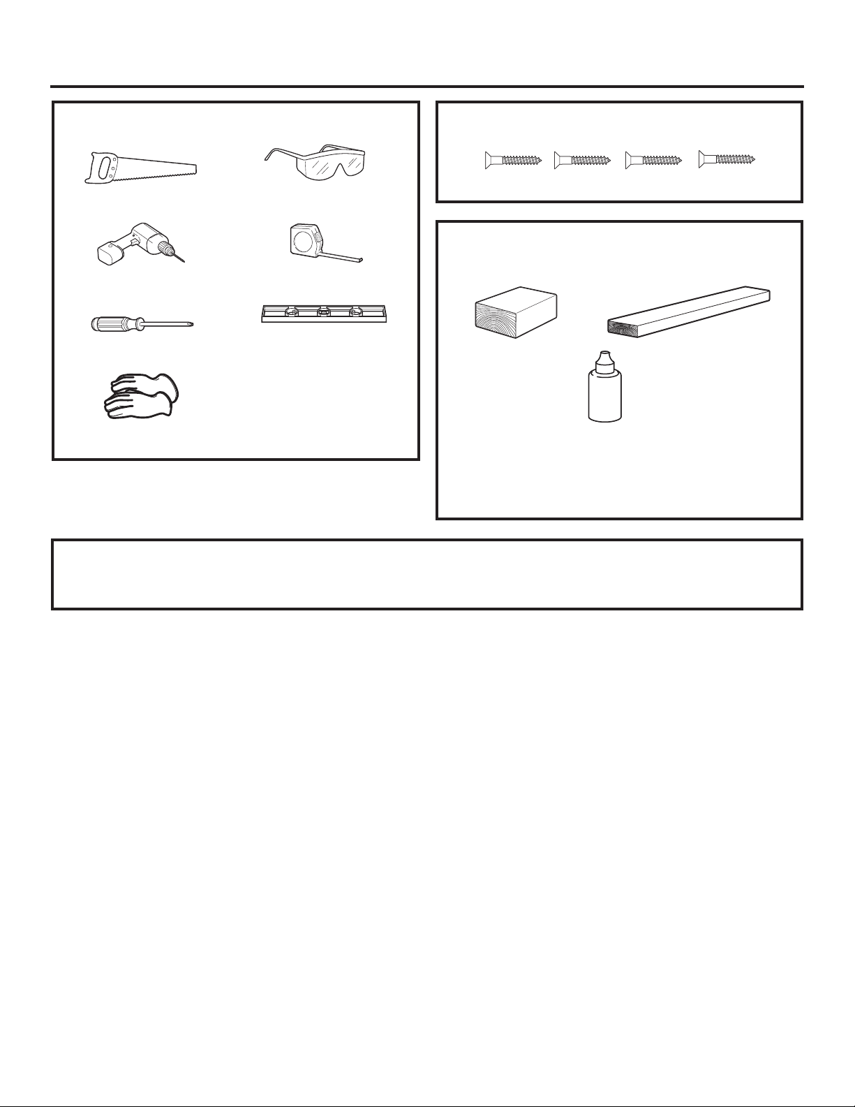
TOOL AND MATERIALS REQUIRED
ŶSafety Glasses
ŶPhillips screwdriver
ŶDrill and appropriate bits (Brad point recommended
for drilling through wood panels)
ŶCustom panel
ŶCustom handle (optional)
ŶAdhesive recommended for metal to wood
ŶAdhesive recommended for plastic to wood
PARTS SUPPLIED
ŶLamp Jewel
ŶMetal mounting panel
ŶBag of #6 size screws
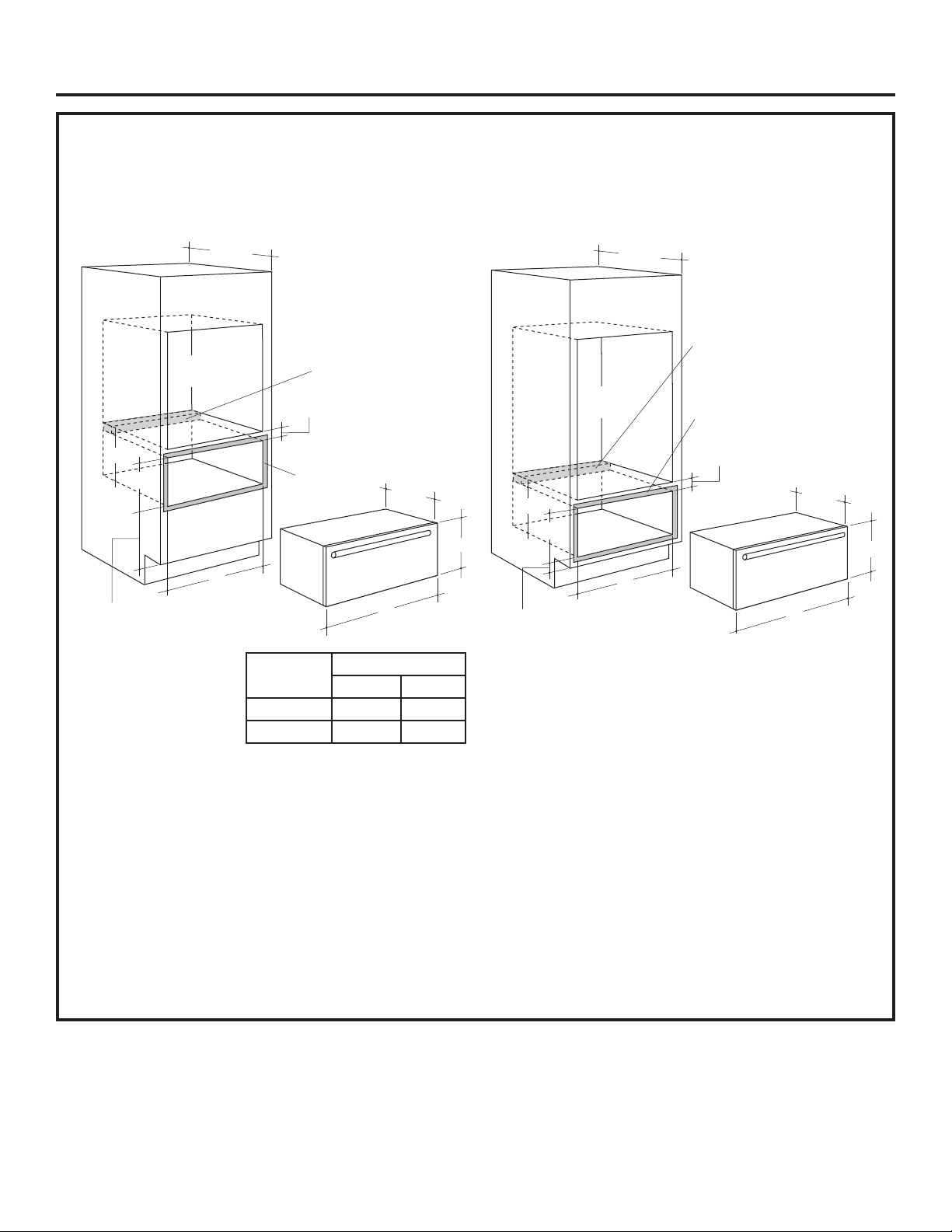
This kit contains a mounting panel to support a trimless
custom drawer front up to 3/4” thick. The tubular handle
can be reinstalled onto the custom panel with longer
screws (not provided). Or, the original handle can be
replaced with a custom handle of your choice. (Handle
is not supplied.) Choose a custom handle to match or
complement cabinetry hardware.
IMPORTANT: The warming drawer should be installed
according to the installation instructions packed with the
product. The original drawer front will be removed and
replaced with a custom panel.
ŶCut edges of the drawer panel will be seen and must
be finished for best appearance.
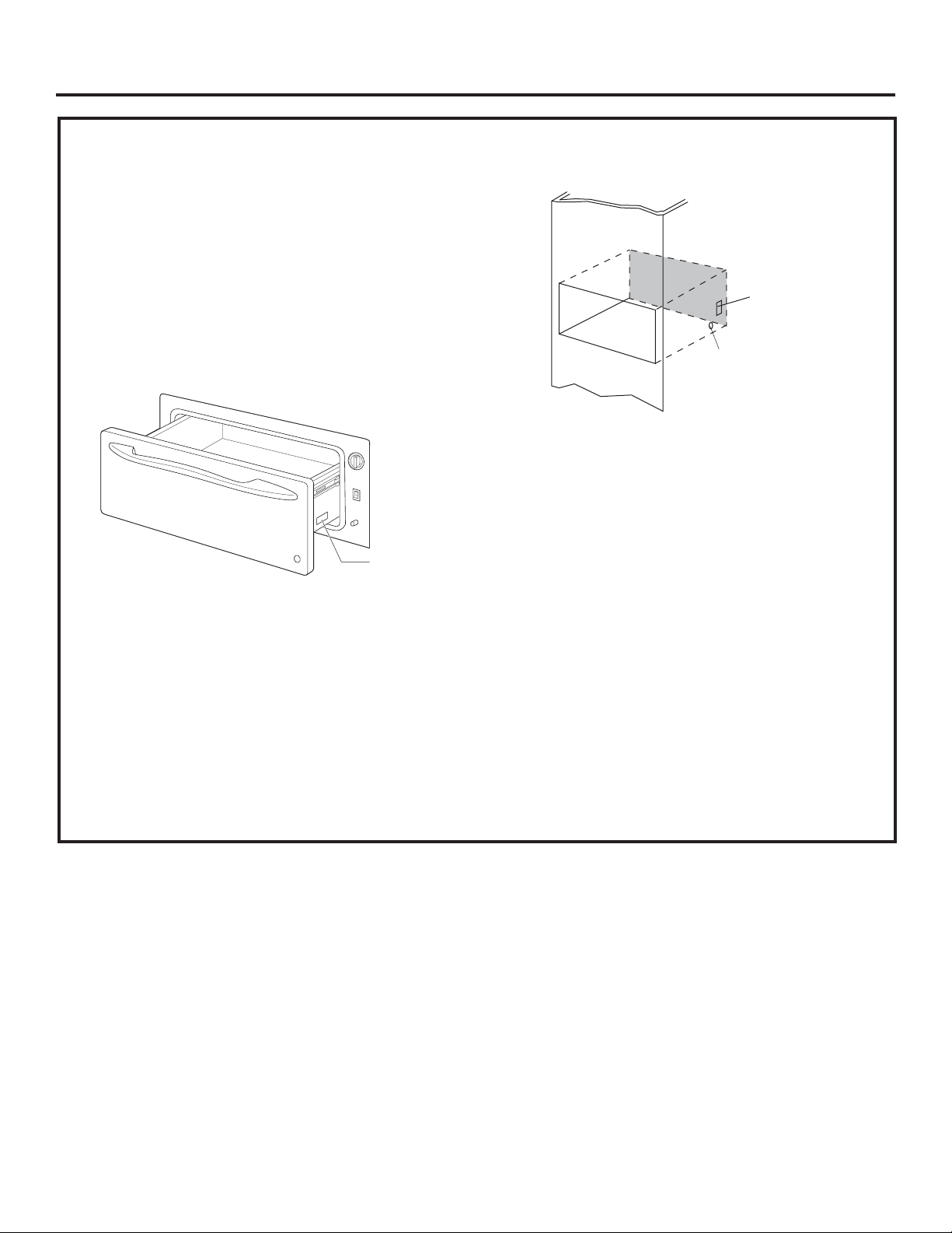
STEP 1 PREPARE DRAWER FOR
PANEL INSTALLATION
ŶOpen the drawer fully.
ŶTurn the warming drawer off.
STEP 3 PREPARE CUSTOM PANEL
ŶThe custom panel size is determined by the cabinetry
dimensions and spacings.
ŶOnce the custom panel size is determined, place
the metal panel on the custom panel and check the
squareness and correct placement of the metal panel,
and mark the hole for the indicator light. Confirm that
the hole marking provides the indicator light to the
right side of the custom panel appearance side.
ŶDrill a 5/16” hole. A Brad point drill bit is
recommended.
STEP 2 REMOVE ORIGINAL
DRAWER FRONT
ŶRemove seven #8 screws. Remove four from top
inside and three from bottom. Set these screws aside
– they are no longer needed.
– Support the drawer front as you remove screws to
prevent the possibility of falling.
ŶThe custom drawer front panel, both raised and flat
design, should be constructed in the same manner as
typical cabinet doors.
ŶOrder the custom drawer panel from the cabinet
manufacturer. Be sure to provide the exact
dimensions so that the panel is constructed
accurately.
ŶOrder the optional custom handle to complement or
match surrounding cabinetry handles.
BEFORE YOU BEGIN
Read these instructions completely and carefully.
ŶIMPORTANT–Save these instructions for
local inspector’s use.
ŶIMPORTANT–Observe all governing
codes and ordinances.
ŶNote to Installer – Be sure to leave these
instructions with the consumer.
ŶNote to Consumer – Keep these instructions for
future reference.
ŶSkill level – Installation of this custom panel kit
requires a qualified installer or service technician.
ŶProper installation is the responsibility of the installer.
ŶProduct failure due to improper installation is NOT
covered under the warranty.
Installation
Instructions
WARMING DRAWER CUSTOM
PANEL ACCESSORY KIT
ZXD30B
For installation of 30” wide warming
drawer custom panel and custom handle.