Monogram ZKW700S User manual

INSTALLATION
INSTRUCTIONS
Electric Warming Drawer
ZKW700S, ZKW700P, ZTW900S and ZTW900P
Para consultar una version en español
de este manual de instrucciones, visite nuestro
sitio de internet monogram.com.
MONOGRAM.COM

231-2000654 Rev. 3
Safety Information
FRONT PANEL ACCESSORIES
ZXW900
This kit provides for the installation of a custom front
panel on 30” models.
NOTE: The original drawer front will be removed and
discarded when this kit is used. The tubular handle can be
reinstalled onto the custom panel with longer screws (not
provided). Or, the original handle can be replaced with a
custom handle of your choice. (Handle is not supplied.)
Choose a custom handle to match or complement
cabinetry hardware.
For more Accessories or purchasing information please
refer to Assistance/Accessories section of Monogram
Warming Drawer Owner’s Manual.
BEFORE YOU BEGIN
Read these instructions completely and carefully.
ŶIMPORTANT — Save these instructions for local
inspector’s use.
ŶIMPORTANT — Observe all governing codes and
ordinances.
ŶNote to Installer – Be sure to leave these
instructions with Consumer.
ŶNote to Consumer – Keep these instructions for
future reference.
ŶCompletion Time — 1 to 3 Hours.
Ŷ3URSHULQVWDOODWLRQLVWKHUHVSRQVLELOLW\RIWKHLQVWDOOHU
3URGXFWIDLOXUHGXHWRLPSURSHULQVWDOODWLRQLVQRW
covered under the warranty. See Owner’s Manual for
warranty information.
Ŷ8VHWKLVDSSOLDQFHRQO\IRULWVLQWHQGHGSXUSRVH
Ŷ&KHFNZLWKORFDOXWLOLWLHVIRUHOHFWULFDOFRGHVWKDW
apply in your area. Local codes vary. Installation
electrical connections and grounding must comply
with applicable codes. In the absence of local codes,
the drawer should be installed in accordance with
1DWLRQDO(OHFWULFDO&RGH$16,1)3$RUODWHVW
edition.
WARNING
$QDQWLWLSEUDFHPXVWEHLQVWDOOHGWR
prevent the drawer from tipping forward when opened
and loaded. Failure to do so could result in personal injury.
WARNING
Ŷ7KLVDSSOLDQFHPXVWEHSURSHUO\JURXQGHG6HH
“Grounding the Appliance.”
Ŷ,QVXUHWKDWWKHSRZHUFRUGGRHVQRWFRQWDFWWKHKRW
surface on the bottom of ovens, cooktops, or other
appliances.
Ŷ,I\RXUHFHLYHGDGDPDJHGZDUPLQJGUDZHU\RX
should contact your dealer
Ŷ)RU0RQRJUDPORFDOVHUYLFHLQ\RXUDUHD
1.800.444.1845.
Ŷ)RU0RQRJUDP6HUYLFHLQ&DQDGDFDOO
1.800.561.3344.
Ŷ)RU0RQRJUDP3DUWVDQG$FFHVVRULHVFDOO
1.800.626.2002.
MODELS AVAILABLE
30” Models: ZTW900S, ZTW900P
27” Models: ZKW700S, ZKW700P
CONTENTS
Design Information
Models Available.....................................................2
Accessories.............................................................2
Product Dimensions...............................................3
Grounding the Appliance ......................................3
Installation Preparation
Tools and Materials Required ...........................4
Remove Packaging..............................................4
Installation Options
Installation Below a Single Oven.....................5
Installation Below a Double Oven....................5
Installation Below a Countertop .....................6
Provide Cabinet Support.....................................7
Flushmount Installation Preparation.................7
Install Anti-Tip Brackets......................................8
Install Warming Drawer.......................................8
Installation Instructions : Warming Drawer
Custom Panel Accessory Kit ZXW900..................9
Before You Begin.................................................9
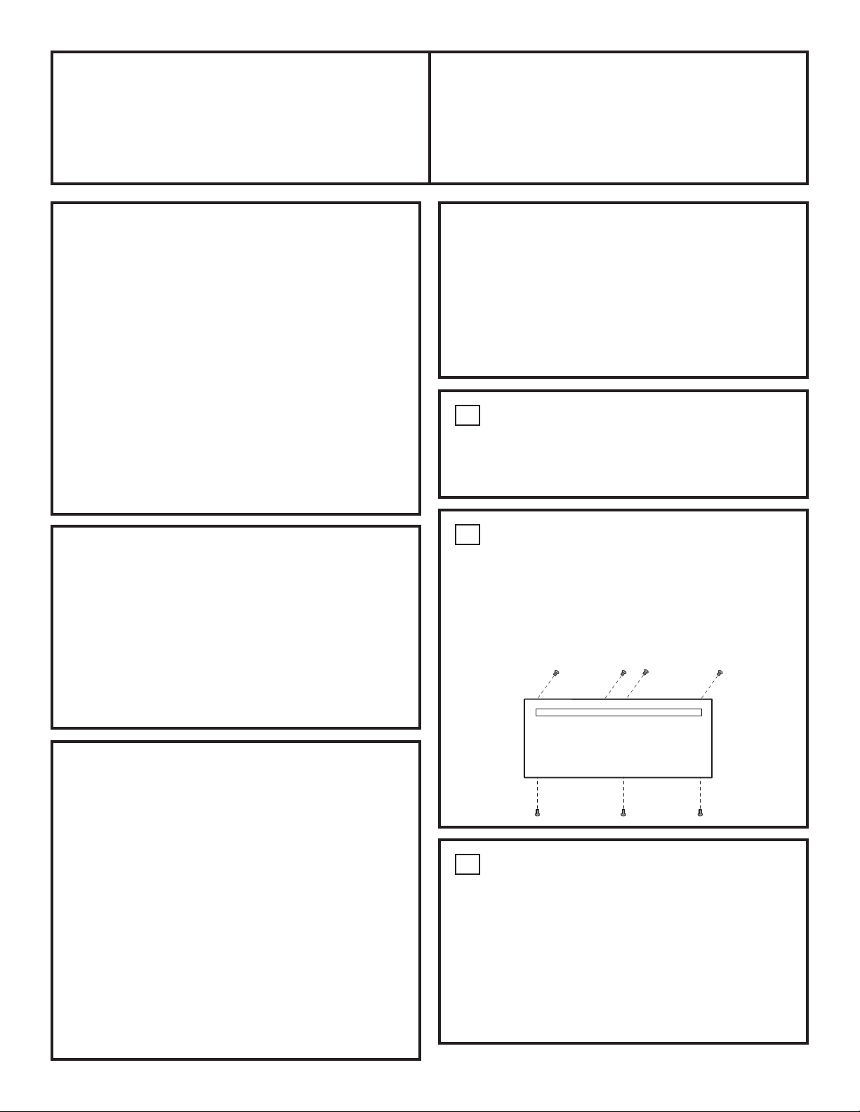
Step 1, Prepare Drawer For Panel Installation..9
Step 2, Remove Original Drawer Front..............9
Step 3, Prepare Custom Panel ...........................9
Step 4, Secure Custom Panel to
Metal Mounting Panel...........................10
Step 5A, For Panels Less Than 3/4” Thick .....10
Step 5B, For 3/4” (Or Greater) Thick Panels
Step 6, Install Lamp Jewel................................10
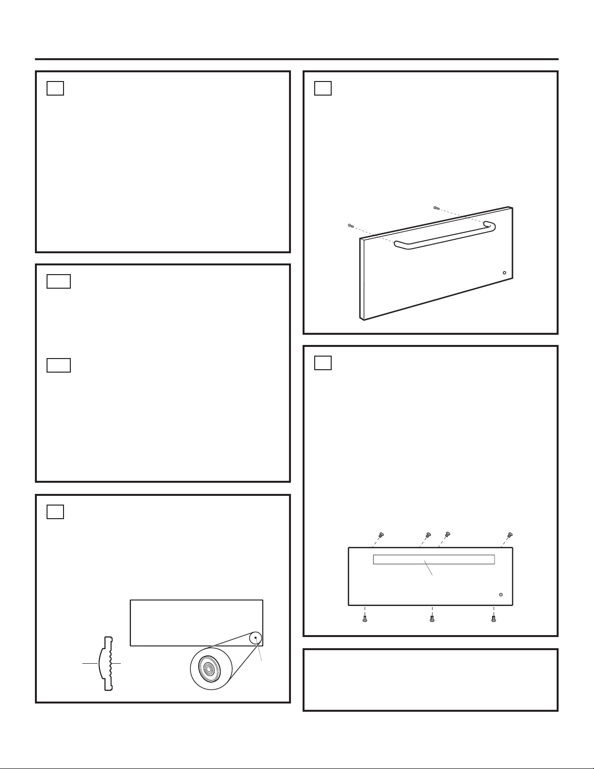
Step 7, Reinstall Original Handle or
Optional Custom Handle......................10
Step 8, Install Assembled Panel
to the Drawer.........................................10

31-2000654 Rev. 3 3
PRODUCT DIMENSIONS AND CLEARANCES
Design Information
´ ´
A
BC
1” Including
Handle
Drawer
Open
´ Models Dimensions
ABC
=7:6DQG=7:3 ´ ´ ´
=.:6DQG=.:3 ´ ´ ´
=;63DQG=;: Dimensions to be
determined by
panel and handle
´
GROUNDING THE APPLIANCE
Please read carefully.
Do not use an extension cord or adapter plug with this
appliance. Follow National electrical codes or prevailing
local codes and ordinances.
This warming drawer must be supplied with 120V, 60Hz,
and connected to an individual, properly grounded
branch circuit, and protected by a 15 or 20 amp circuit
breaker or time delay fuse.
Ŷ$SURSHUO\JURXQGHGSURQJUHFHSWDFOHVKRXOGEH
located within reach of the drawers’ 56” long power
cord.
Ŷ/RFDWHWKHUHFHSWDFOHLQDQDGMDFHQWFDELQHW
– within 42” of the right side or,
– within 16” of the left side or,
Ŷ$UHFHVVHGUHFHSWDFOHPD\EHORFDWHGRQWKHULJKWVLGH
RIWKHFXWRXW´IURPWKHEDFNRIWKHFDELQHW,QWKLV
location, the excess power cord should be coiled and
taped to the right side of the unit.
Ŷ:KHQWZRZDUPLQJGUDZHUVDUHLQVWDOOHGVLGHWRVLGH
they can operate from the same receptacle.
Please read carefully.
The power cord of this appliance is equipped with a
SURQJJURXQGLQJSOXJWKDWPDWHVZLWKDVWDQGDUG
SURQJJURXQGLQJZDOOUHFHSWDFOHWRPLQLPL]HWKH
possibility of electric shock. The customer should have
the wall receptacle and circuit checked by a qualified
electrician to make sure the receptacle is properly
grounded and has the correct polarity.
Ŷ:KHUHDVWDQGDUGSURQJZDOOUHFHSWDFOHLV
encountered, it is the personal responsibility and
obligation of the customer to have it replaced with a
SURSHUO\JURXQGHGSURQJZDOOUHFHSWDFOH
Do not, under any circumstances, cut or remove the third
(ground) prong from the power cord.
DO NOT USE AN EXTENSION CORD WITH THIS
APPLIANCE.
FOLLOW NATIONAL ELECTRICAL CODES AND
ORDINANCES.
Recessed
5HFHSWDFOH´
Max. From Rear
on Right Side
'ULOO´+ROH)RU
3RZHU&RUG)RU
Left or Right Side
Outlet Location
5DWLQJ3ODWH

431-2000654 Rev. 3
Installation Preparation
REMOVE PACKAGING
3ODFH:DUPLQJ'UDZHURQFDUWRQRUSURWHFWLYHSDGWRSUHYHQWGDPDJHWRGUDZHUIURQWRUILQLVKHGIORRULQJ
TOOLS REQUIRED MATERIALS REQUIRED
(provided)
MATERIALS REQUIRED
(not provided)
Runners must be level, rigidly mounted and capable
of supporting 150 pounds.
Safety Glasses
Cut Resistant Gloves
Drill and
1/16” Bit Measuring Tape
3KLOOLSV6FUHZGULYHU
Hand Saw
Level
4 Wood Screws
2x2 or 2x4
Wood Block
IRU$QWL7LS
Security
Adhesive or other hardware
for installing runners or shelf to
support warmer drawer
2x2 or 2x4
Lumber for
Runners

31-2000654 Rev. 3 5
Installation Preparation
INSTALLATION OPTIONS
When installed under a wall oven:
Warming drawers are approved for installation below
only certain specified wall oven models. See the
label attached to the top of the warming drawer for
approved models.
Ŷ:KHQLQVWDOOHGWKHIURQWIDFHRIWKHGUDZHUZLOOEH
nearly flush with adjacent cabinetry doors.
Ŷ'UDZHURYHUODSVZLOOFRQFHDOFXWHGJHVRQDOOVLGHVRI
the opening.
NOTE: Additional clearance between cutouts may be
required. Check to be sure that oven supports above the
Warming Drawer location does not obstruct the required
LQWHULRU´GHSWKDQG´KHLJKW
The rough opening for the drawer must be:
Ŷ'HSWK´PLQIURPLQVLGHEDFNWRIURQWRIFDELQHW
frame.
Ŷ:LGWK´IRU´ZLGHPRGHOV´IRU´
wide models.
Ŷ+HLJKW´
Ŷ$OORZ´PLQEHWZHHQRYHQDQGGUDZHUFXWRXWVIRU
clearance of overlaps.
NOTE: If you are installing in frameless cabinets, it
may be necessary to install 1/2” wide cleats to accept
drawer mounting screws. See drawer for mounting
screw locations.
Installation Below
a Double Oven
[RU[$QWL7LS
Block Against Rear
:DOO´)URP)ORRU
to Bottom of Block
1” Min. Above Toekick
Allow 5/8”
Overlap on
All Sides
´
Min.
Inside
Oven
Cutout
2” Min.
´
A
B
´
´
´
Installation Below
a Single Oven
[RU[$QWL7LS
Block Against Rear
:DOO´)URP)ORRU
to Bottom of Block
1” Min. Above Toekick or Adjust
to Oven Installation Height
´
Min.
Inside
Oven
Cutout
2” Min.
´
A
B
´
´
´
Allow 5/8”
Overlap on
All Sides
Models
Dimensions
A B
=7:6=7:3 ´ ´
=.:6=.:3 ´ ´

631-2000654 Rev. 3
Installation Preparation
INSTALLATION BELOW A COUNTERTOP
Ŷ:KHQLQVWDOOHGWKHIURQWIDFHRIWKHGUDZHUZLOOEH
nearly flush with adjacent cabinetry doors.
Ŷ'UDZHURYHUODSVZLOOFRQFHDOFXWHGJHVRQDOOVLGHVRI
the opening.
Ŷ7KHURXJKRSHQLQJIRUWKHGUDZHUPXVWEH
±'HSWK´PLQIURPLQVLGHEDFNWRIURQWRI
cabinet frame.
±:LGWK´IRU´ZLGHPRGHOV
´IRU´ZLGHPRGHOV
±+HLJKW´
Ŷ´PLQDERYHIORRURU´DERYHWRHNLFN´
from floor to bottom of cutout is recommended for
under countertop installation.
Installation below a cooktop:
Warming drawers are approved for installation below
only certain specified cooktop models. See the label
attached to the top of the warming drawer for approved
models. A solid barrier and air gap between cooktop and
warming drawer is required. See NOTE above.
*NOTE: When installing the warming drawer below a
cooktop, a solid barrier must be installed at least 1” from
the lowest point of the bottom of cooktop burner box to
WKHWRSRIFXWRXW8VHDQ\VROLGPDWHULDOVXFKDV´
thick plywood. Allow at least 1/4” air gap between the
barrier and the top of the warming drawer. See label on
top of the warming drawer for approved cooktop models.
Installation below a cabinet drawer:
The warming drawer may be installed beneath a cabinet
drawer. In this installation, a solid barrier should be
installed above the warming drawer to block access.
8VHDQ\VROLGPDWHULDOVXFKDV´WKLFNSO\ZRRG$OORZ
at least 1/4” air gap between the barrier and the top of
the warming drawer. Observe the 5” min. above the floor
or 1” above the toekick minimum installation height.
NOTE: If you are installing in frameless cabinets, it may
be necessary to install 1/2” wide cleats to accept drawer
mounting screws. See drawer to find exact locations of
mounting screws.
Side to Side Installation:
Install two warming drawers in separate cutouts.
Allow 2” min. between cutouts.
Side to Side Installation
2”
Min.
Install a Solid Barrier
Below a Cooktop
See Note
´&DELQHW7RS
36”
Countertop
Height
1” Min.*
´
´
A
´ 25”
´0LQ
1/4”
Air
Gap
Solid Barrier
Electrical Outlet 42”
Max. From Right Side
Install a Solid Barrier
and a 1/4” Air Gap
Above Warming Drawer
Electrical
Outlet 16”
Max. From
Left Side
Install 2x4 or 2x2
$QWL7LS%ORFN$JDLQVW
5HDU&DELQHW:DOO´
From Floor to Bottom
of Block
Electrical Outlet
Flush With Side of
&DELQHW´0D[
Models
Dimensions
A
=7:3
=7:6 ´
=.:6
=.:3 ´

31-2000654 Rev. 3
Installation Preparation
PROVIDE CABINET SUPPORT
IMPORTANT: When installed below a single or double
oven, check to be sure that any oven supports above
WKHFXWRXWGRQRWREVWUXFWWKH´UHTXLUHGGHSWKRI
the warming drawer cutout.
Ŷ$´PLQFOHDUDQFHEHWZHHQRYHQDQGZDUPLQJ
drawer cutouts are required. Additional clearance may
be required if 2 x 4 blocks are used to support runners
or solid floor of the oven above.
Ŷ7KHZDUPHUGUDZHUPD\EHVXSSRUWHGE\HLWKHUD
solid bottom, 2 x 4 or 2 x 2 runners.
Ŷ7KHVXSSRUWPXVWEHOHYHODQGULJLGO\PRXQWHGIOXVK
with the bottom edge of the cutout.
– There is no way to level the drawer once it has been
installed. Be sure supports are level.
Ŷ7KHHQWLUHZHLJKWRIWKHGUDZHULVVXSSRUWHGE\
the runners or solid floor and must be capable of
supporting 150 lbs.
FLUSHMOUNT INSTALLATION PREPARATION
PREPARE THE INTERIOR
Cut and install side cleats:
ŶCut side wood cleats to height of cabinet opening and
DSSUR[´LQGHSWK,QVWDOORQHDFKVLGH(IURP
the front face of the cabinet.
Cut and install bottom cleat:
ŶCut bottom wood cleat to a height of 1” minimum,
a depth of the cabinet minus E and a width of the
cabinet opening D.
Install onto the cabinet floor between the side cleats,
push it all the way back against cabinet wall and make
sure its front face aligns with the front faces of the
side cleats (E gap from the front cabinet face).
2”x4” or
Equivalent Runners
25”
30”
´´
22”
´
2”x4” or
Equivalent Runners
E
C
B
D
AATOP
VIEW
Front Face of Cabinet EE
A A
C
D
30” 27”
A Side cleats depth ´PLQ ´PLQ
B Bottom cleat height 1” min. 1” min.
C Bottom cleat depth Cabinet depth
minus E Cabinet depth
minus E
D Bottom cleat width ò´PLQ±´
max. (30” minus
2 side cleat
thicknesses of
´HDFK
25 ½” min. – 26”
PD[´PLQXV
2 side cleat
WKLFNQHVVHVRI
3/4” each)
E All three cleats
inset from cabinet
front
´ ´

831-2000654 Rev. 3
INSTALL ANTI-TIP BRACKETS
WARNING ANTI-TIP PRECAUTIONS
$QDQWLWLSEUDFHPXVWEHLQVWDOOHGWRSUHYHQWWKHGUDZHU
from tipping forward when opened and loaded. Failure to
do so could result in personal injury.
INSTALL WARMING DRAWER
Ŷ6OLGHWKHOHIWFRUQHURIWKHGUDZHULQWRWKHRSHQLQJ
Ŷ3XVKWKHSRZHUFRUGLQWRWKHKROHOHDGLQJWRWKHRXWOHW
location. Thread the cord through as the drawer is
being pushed back into the opening. Check to be
sure the power cord does not get trapped under the
drawer.
– If the outlet is installed inside the opening, plug
the cord into the outlet. In this location, the excess
power cord length should be coiled and taped to the
right side of the unit.
Ŷ3XVKWKHGUDZHUEDFNXQWLO
the front flange is flush to the
cabinet front.
Ŷ2SHQWKHGUDZHUIXOO\
Ŷ'ULOOSLORWKROHVWKURXJKWKH
holes in the overlapping frame,
one on each corner.
Ŷ'ULYHWKHZRRGVFUHZVSURYLGHGLQWRHDFKFRUQHU
Install 2x4 or 2x2
$QWL7LS%ORFN
Against Rear
&DELQHW:DOO´
From Floor to
Bottom of Block
2x4 or 2x2
Runners or
Solid Bottom
´
Installation Preparation

31-2000654 Rev. 3
Installation
Instructions
WARMING DRAWER CUSTOM
PANEL ACCESSORY KIT
ZXW900
For installation of 30” wide warming
drawer custom panel and custom handle.
BEFORE YOU BEGIN
Read these instructions completely and carefully.
ŶIMPORTANT–Save these instructions
for local inspector’s use.
ŶIMPORTANT–Observe all governing
codes and ordinances.
ŶNote to Installer – Be sure to leave these
instructions with the consumer.
ŶNote to Consumer – Keep these instructions for
future reference.
ŶSkill level – Installation of this custom panel kit
requires a qualified installer or service technician.
Ŷ3URSHULQVWDOODWLRQLVWKHUHVSRQVLELOLW\RIWKHLQVWDOOHU
Ŷ3URGXFWIDLOXUHGXHWRLPSURSHULQVWDOODWLRQLV127
covered under the warranty.
TOOL AND MATERIALS REQUIRED
Ŷ6DIHW\JODVVHV
ŶCut resistant gloves
Ŷ3KLOOLSVVFUHZGULYHU
Ŷ'ULOODQGDSSURSULDWHELWV%UDGSRLQWUHFRPPHQGHG
for drilling through wood panels)
Ŷ&XVWRPSDQHO
Ŷ&XVWRPKDQGOHRSWLRQDO
Ŷ$GKHVLYHUHFRPPHQGHGIRUPHWDOWRZRRG
Ŷ$GKHVLYHUHFRPPHQGHGIRUSODVWLFWRZRRG
PARTS SUPPLIED
Ŷ/DPS-HZHO
Ŷ0HWDOPRXQWLQJSDQHO
Ŷ%DJRIVL]HVFUHZV
This kit contains a mounting panel to support a trimless
custom drawer front up to 3/4” thick. The tubular
handle can be reinstalled onto the custom panel with
longer screws (not provided). Or, the original handle
can be replaced with a custom handle of your choice.
(Handle is not supplied.) Choose a custom handle to
match or complement cabinetry hardware.
IMPORTANT: The warming drawer should be
installed according to the installation instructions
packed with the product. The original drawer front will
be removed and replaced with a custom panel.
Ŷ&XWHGJHVRIWKHGUDZHUSDQHOZLOOEHVHHQDQG
must be finished for best appearance.
Ŷ7KHFXVWRPGUDZHUIURQWSDQHOERWKUDLVHGDQGIODW
design, should be constructed in the same manner
as typical cabinet doors.
Ŷ2UGHUWKHFXVWRPGUDZHUSDQHOIURPWKHFDELQHW
manufacturer. Be sure to provide the exact
dimensions so that the panel is constructed
accurately.
Ŷ2UGHUWKHRSWLRQDOFXVWRPKDQGOHWRFRPSOHPHQWRU
match surrounding cabinetry handles.
1PREPARE DRAWER FOR PANEL
INSTALLATION
Ŷ2SHQWKHGUDZHUIXOO\
Ŷ7XUQWKHZDUPLQJGUDZHURII
2REMOVE ORIGINAL DRAWER
FRONT
Ŷ5HPRYHVHYHQVFUHZV5HPRYHIRXUIURPWRS
inside and three from bottom. Set these screws
aside – they are no longer needed.
Ŷ6XSSRUWWKHGUDZHUIURQWDV\RXUHPRYHVFUHZVWR
prevent the possibility of falling.
3PREPARE CUSTOM PANEL
Ŷ7KHFXVWRPSDQHOVL]HLVGHWHUPLQHGE\WKH
cabinetry dimensions and spacings.
Ŷ2QFHWKHFXVWRPSDQHOVL]HLVGHWHUPLQHGSODFH
the metal panel on the custom panel and check the
squareness and correct placement of the metal panel,
and mark the hole for the indicator light. Confirm that
the hole marking provides the indicator light to the
right side of the custom panel appearance side.
Ŷ'ULOOD´KROH$%UDGSRLQWGULOOELWLVUHFRPPHQGHG

10 31-2000654 Rev. 3
Installation
Insert
Jewel
Appearance
Side
This Side
A
gainst
Wood
Custom Handle
or Original Handle
4SECURE CUSTOM PANEL TO
METAL MOUNTING PANEL
Ŷ/D\WKHFXVWRPSDQHODSSHDUDQFHVLGHGRZQRQD
clean surface.
Ŷ5HPRYHDOOWDSHDQGSDFNLQJPDWHULDOIURPWKH
metal panel.
Ŷ3ODFHWKHIODWVLGHRIWKHPHWDOSDQHORQWRWKHEDFN
side of the custom panel, with the mounting flanges
facing up.
Ŷ$OLJQWKHODPSKROHLQWKHSDQHOZLWKWKHPRXQWLQJ
panel.
Ŷ&RQILUPVTXDUHQHVVDQGFRUUHFWSRVLWLRQRIWKH
metal panel to the custom panel.
7REINSTALL ORIGINAL HANDLE
OR OPTIONAL CUSTOM HANDLE
Ŷ$FXVWRPKDQGOHQRWVXSSOLHGPD\EHLQVWDOOHG
Ŷ'ULOOSLORWKROHVWKURXJKWKHIURQWRIWKHFXVWRP
panel and through the metal panel to match the
chosen handle.
NOTE: The handle screws should be installed through
the metal panel, the custom panel and into the
custom or original handle.
8INSTALL ASSEMBLED PANEL TO
THE DRAWER
Ŷ'HWHUPLQHZKLFKKROHVLQWKHPHWDOSDQHOOLQHXS
with the holes in the exposed drawer front and
marked the screw hole locations onto the custom
panel.
Ŷ'ULOO´GHHSKROHVLQWRWKHFXVWRPSDQHOIRU
FOHDUDQFHWRWKHVFUHZV7KHVFUHZVZLOO
extend into the custom panel slightly.
Ŷ8VLQJWKHVFUHZVVXSSOLHGLQWKHEDJLQVWDOOWKH
custom panel assembly to the exposed drawer front
with seven screws.
Ŷ7KHRULJLQDOVFUHZVDUHQRWQHHGHG
NOTE:3URGXFWLPSURYHPHQWLVDFRQWLQXLQJHQGHDYRU
at Monogram Appliances. Therefore, materials,
appearance and specifications are subject to change
without notice.
6INSTALL LAMP JEWEL
Ŷ7XUQWKHDVVHPEO\DSSHDUDQFHVLGHXS
Ŷ8VHSODVWLFWRZRRGDGKHVLYHWRVHFXUHWKHODPS
jewel to the front of the wood panel. On the side
with the bulge, (see illustration) apply a small bead
RIDGKHVLYHDURXQGWKHRXWVLGHHGJH3ODFHWKH
jewel into the drilled hole.
5A FOR PANELS LESS THAN
3/4” THICK
Ŷ6HSDUDWHWKHFXVWRPSDQHODQGPHWDOSDQHO
Ŷ$SSO\DIHZKRUL]RQWDOEHDGVRIDGKHVLYHWRWKH
metal panel. Avoid adhesive within 1” of lamp hole
area and outer edges.
5B FOR 3/4” (OR GREATER)
THICK PANELS
Ŷ6HSDUDWHWKHFXVWRPSDQHODQGPHWDOSDQHO
Ŷ8VHWKHPHWDOSDQHODVDWHPSODWH3RVLWLRQWKH
metal panel over the back side of the custom panel
and drill pilot holes. Drill pilot holes sized to match
screws being used (screws not provided).
NOTE: Select screw length carefully to avoid
penetration of the finished side.

31-2000654 Rev. 3 11
Notes

NOTE: While performing installations described in this
book, safety glasses or goggles should be worn.
For Monogram®local service in your area, call
1.800.444.1845.
NOTE:3URGXFWLPSURYHPHQWLVDFRQWLQXLQJHQGHDYRU
at GE Appliances. Therefore, materials, appearance
and specifications are subject to change without notice.
5HY
*($
3ULQWHGLQWKH&KLQD

INSTRUCCIONES
DE INSTALACIÓN
Cajón para Calentar Eléctrico
ZKW700S, ZKW700P, ZTW900S y ZTW900P
MONOGRAM.COM

231-2000654 Rev. 3
Información de Seguridad
ACCESORIOS DEL PANEL FRONTAL
ZXD30B
Este kit brinda la instalación de un panel frontal a medida en
modelos de 30”.
NOTA: El frente del cajón original se deberá retirar y descartar
cuando se use este kit. La manija cilíndrica se podrá volver
a instalar en el panel a medida con tornillos más largos (no
provistos). O, la manija original se podrá volver a colocar con una
manija a medida de su elección. (No se suministra la manija).
Elija una manija a medida que coincida o se complemente con el
material de los gabinetes.
Para más Accesorios o información de compras, por favor
consulte la sección de Asistencia/ Accesorios del Manual del
Propietario del Cajón para Calentar de Monogram.
ANTES DE COMENZAR
Lea estas instrucciones en su totalidad y atentamente.
ŶIMPORTANTE — Conserve estas instrucciones
para uso del inspector local.
ŶIMPORTANTE — Cumpla con todos los códigos y
ordenanzas gubernamentales.
ŶNota para el Instalador – Asegúrese de entregarle estas
instrucciones al Consumidor.
ŶNota para el Comprador – Conserve estas instrucciones
para referencia futura.
ŶTiempo de instalación – Aproximadamente entre
1 y 3 horas.
Ŷ (OLQVWDODGRUWLHQHODUHVSRQVDELOLGDGGHHIHFWXDUXQD
instalación adecuada. Si se producen fallas en el producto
debido a una instalación inadecuada, la Garantía no cubrirá
las mismas. Para obtener información sobre la garantía,
consulte el Manual del Propietario.
Ŷ 8VHHVWHHOHFWURGRPpVWLFRVyORSDUDVXSURSyVLWRRULJLQDO
Ŷ &RQVXOWHDORVVHUYLFLRVORFDOHVVREUHTXpFyGLJRV
HOpFWULFRVVHDSOLFDQHQVXiUHD/RVFyGLJRVORFDOHVYDUtDQ
/DLQVWDODFLyQODVFRQH[LRQHVHOpFWULFDV\ODFRQH[LyQ
a tierra deberán cumplir con los códigos aplicables. En
ausencia de códigos locales, el cajón se deberá instalar
de acuerdo con el Código de Electricidad Nacional ANSI/
NFPA 70-1990 o su edición más reciente.
ADVERTENCIA
Se deberá instalar la abrazadera anti
volcaduras para evitar que el cajón se voltee hacia adelante cuando
se abra y cargue. Si esto no se cumple, se podrán sufrir lesiones
personales.
ADVERTENCIA
Ŷ (VWHHOHFWURGRPpVWLFRGHEHUiHVWDUFRUUHFWDPHQWH
conectado a tierra. Consulte la sección de “Conexión a
7LHUUDGHO(OHFWURGRPpVWLFR´
Ŷ $VHJ~UHVHGHTXHHOFDEOHGHFRUULHQWHQRWHQJDFRQWDFWR
con las superficies calientes de la parte inferior de los
KRUQRVVXSHUILFLHVGHFRFFLyQXRWURVHOHFWURGRPpVWLFRV
Ŷ 6LHOFDMyQSDUDFDOHQWDUTXHUHFLELyHVWiGDxDGRVH
deberá comunicar con su vendedor minorista.
Ŷ 3DUDDFFHGHUDOVHUYLFLRWpFQLFRORFDOGH0RQRJUDPHQVX
área, llame al 1.800.444.1845.
Ŷ 3DUDDFFHGHUDO6HUYLFLR7pFQLFRGH0RQRJUDPHQ&DQDGi
llame al 1.800.561.3344.
Ŷ 3DUDDFFHGHUD3LH]DV\$FFHVRULRVGH0RQRJUDPOODPHDO
1.800.626.2002.
CONTENIDO
Información de Dise
Modelos Disponibles........................................................2
Accesorios.........................................................................2
Dimensiones del Producto ..............................................3
Conexión a Tierra del Electrodoméstico........................3
Preparación de la Instalación
Herramientas y Materiales Requeridos ......................4
Retiro del Embalaje.......................................................4
Opciones de Instalación
Instalación Debajo de un Horno Simple.................5
Instalación Debajo de un Horno Doble...................5
Instalación Debajo de la Mesada ............................6
Brinde el Soporte del Gabinete....................................7
Preparación para la Instalación
con Montaje Nivelado................................................7
Instale los Soportes Anti Volcaduras..........................8
Instale el Cajón para Calentar......................................8
Instrucciones de instalación : Kit de Accesorios
del Panel a Medida del Cajón para Calentar ZXW900...9
Antes de Comenzar.......................................................9
Paso 1, Prepare el Cajón Para la Instalación
en el Panel ........................................................9
Paso 2, Retire el Frente del Cajón Original ...............9
Paso 3, Prepare el Panel a Medida..............................9
Paso 4, Asegure el Panela Medida Sobre
el Panel de Montaje Metálico .......................10
Paso 5A, Para los Paneles con Grosor
Inferior a ¾” ................................................10
Paso 5B, Para Paneles Gruesos de ¾” (o más).......10
Paso 6, Instale la Lámpara.........................................10
Paso 7, Reinstale la Manija Original o la Manija
a Medida Opcional ........................................10
Paso 8, Instale el Panel Ensamblado en el Cajón ...10
MODELOS DISPONIBLES
Modelos de 30”: ZTW900S, ZTW900P
Modelos de 27”: ZKW700S, ZKW700P

31-2000654 Rev. 3 3
DIMENSIONES Y ESPACIOS LIBRES DEL PRODUCTO
Información de Dise
9” 10-1/2”
A
BC
1” Including
Handle
Drawer
Open
23-1/4” Modelos Dimensiones
ABC
ZTW900S y ZTW900P 23-1/4” 26-1/4” 29-3/4”
ZKW700S y ZKW700P 22-26” 26-1/4” 26-3/4”
ZXS900P y ZXW900 Las dimensiones
estarán determinadas
por el panel y la manija.
29-3/4”
CONEXIÓN A TIERRA DEL ELECTRODOMÉSTICO
Lea detenidamente
No use prolongadores ni adaptadores con este
HOHFWURGRPpVWLFR&XPSODFRQORVFyGLJRVGHHOHFWULFLGDG
a nivel nacional o con los códigos y ordenanzas locales
obligatorios.
Este cajón para calentar deberá ser provisto con 120V,
60Hz, y estar conectado a un circuito de empalmes individual
correctamente conectado a tierra, y protegido por un disyuntor
o fusible de retardo de 15 o 20 amp.
Ŷ 8QUHFHSWiFXORGHFDEOHVFRUUHFWDPHQWHFRQHFWDGRD
tierra deberá estar ubicado dentro del alcance del cable de
corriente largo de 56” del cajón.
Ŷ 8ELTXHHOUHFHSWiFXORHQXQJDELQHWHDG\DFHQWH
— dentro de las 42” del lado derecho o,
— dentro de las 16” del lado izquierdo o,
Ŷ 8QUHFHSWiFXORHPSRWUDGRSRGUiHVWDUXELFDGRGHOODGR
derecho del espacio libre, a un mínimo de 7” desde la parte
trasera del gabinete. En esta ubicación, el cable de corriente
excedente deberá estar enroscado y encintado sobre el lado
derecho de la unidad.
Ŷ Cuando se instalen dos cajones para calentar uno al lado del
otro, estos podrán funcionar desde el mismo receptáculo.
Lea detenidamente
El cable de corriente de este electrodoméstico cuenta
con un enchufe de 3 cables (con cable a tierra) que se
conecta a un tomacorriente de pared estándar de 3 cables
con conexión a tierra para minimizar la posibilidad de
descargas eléctricas. El cliente deberá contratar a un
electricista calificado para que controle el receptáculo de
pared y el circuito, a fin de asegurar que el receptáculo
esté correctamente conectado a tierra y que posea la
polaridad adecuada.
Ŷ En caso de contar con un tomacorriente de pared de 2
cables, es la responsabilidad y obligación del cliente
reemplazarlo por un receptáculo de pared de 3 cables
correctamente conectado a tierra.
Nunca, bajo ninguna circunstancia, corte o elimine el
tercer cable (tierra) del cable de corriente.
NO USE PROLONGADORES NI ENCHUFES
ADAPTADORES CON ESTE ELECTRODOMÉSTICO.
CUMPLA CON LOS CÓDIGOS Y ORDENANZAS
NACIONALES DE ELECTRICIDAD.
Receptáculo
empotrado de 7”
de máx. desde
la parte trasera
del lado derecho
Perfore un agüero
de 1 ½” para el cable
de corriente para la
ubicación de salida
izquierda o derecha.
Placa de
Especificaciones
7pFQLFDV

431-2000654 Rev. 3
Preparación de la Instalación
RETIRO DEL EMBALAJE
&RORTXHHO&DMyQSDUD&DOHQWDUHQHOFDUWyQRVREUHODDOPRKDGLOODSURWHFWRUDDILQGHHYLWDUGDxRVVREUHHOIUHQWHGHOFDMyQRHO
acabado del piso.
MATERIALES REQUERIDAS
(provistos)
MATERIALES REQUERIDAS
(no provistos)
Los tirantes deberán estar nivelados, montados de forma
rígida y deberán poder soportar 150 libras.
4 Tornillos de Madera
Bloque de
Madera como
Seguridad Anti
Volcaduras de
2x2 o 2x4
Adhesivos u otros materiales para la instalación
de tirantes o una repisa para sostener el cajón
para calentar.
Madera para
tirantes y
abrazaderas de
2 x 4 o 2 x 2
HERRAMIENTAS REQUERIDAS
Guantes Resistentes a
Cortes
Taladro y broca de 1/16”
Destornillador Phillips
Sierra Manual Gafas de Seguridad
Cinta de Medición
Nivel

31-2000654 Rev. 3 5
Preparación de la Instalación
OPCIONES DE INSTALACIÓN
Cuando se instale debajo de un horno de pared:
Los cajones para calentar se adaptan a instalaciones
debajo de ciertos modelos de horno de pared específicos
únicamente. Consulte la etiqueta adjunta a la parte superior
del cajón para calentar para conocer los modelos que se
adaptan.
Ŷ 8QDYH]LQVWDODGRODFDUDIURQWDOGHOFDMyQHVWDUiFDVL
nivelada con las puertas de los gabinetes adyacentes.
Ŷ Las superposiciones de los cajones esconderán los
extremos puntiagudos en todos los lados de la abertura.
NOTA: Se podrán requerir aberturas adicionales entre los
espacios libres. Asegúrese de que los soportes del horno que
están por encima de la ubicación del Cajón para Calentar no
obstruyan la profundidad interior de 23 ½” y la altura de 9 ¼”
requeridas.
La apertura aproximada del cajón deberá ser de:
Ŷ3URIXQGLGDG0tQLPRGHò´GHVGHODSDUWHLQWHULRUWUDVHUD
hasta el frente del marco del gabinete.
Ŷ$QFKRò´SDUDPRGHORVGH´GHDQFKRò´SDUD
modelos de 30” de ancho.
Ŷ$OWXUDó´
Ŷ'HMHXQPtQLPRGH´HQWUHHOKRUQR\ORVHVSDFLRVOLEUHVGHO
cajón para los espacios de las superposiciones.
NOTA: Si realizará la instalación en gabinetes sin marco,
será necesario instalar ristreles anchos de ½” que acepten los
tornillos de montaje del cajón. Observe el cajón para encontrar
las ubicaciones exactas de los tornillos de montaje.
Instalación Debajo
de un Horno Doble
Bloque anti volcaduras de 2x2
o 2x4 contra la pared trasera
a 9” del piso hasta la parte
inferior del bloque.
Mín. de 1” sobre el zócalo
Permita una
superposición de 5/8”
en todos los costados
Mín. de
òƎ
en el
Interior
Espacio
libre del
horno
Min. de 2”
9”
A
B
9-1/4”
23-1/4”
10-1/2”
Instalación Debajo
de un Horno Simple
Bloque anti
volcaduras de 2x2 o
2x4 contra la pared
trasera a 9” del piso
hasta la parte inferior
del bloque
Mín. de 1” sobre el zócalo o
realice el ajuste a la altura de la
instalación del horno
23-1/2”
Min.
Inside
Espacio
libre del
horno
Mín. de 2”
9”
A
B
9-1/4” 23-1/4”
10-1/2”
Permita una
superposición de 5/8” en
todos los costados
Modelos
Dimensiones
A B
ZTW900S & ZTW900P 28-1/2” 29-3/4”
ZKW700S &ZKW700P 25-1/2” 26-3/4”

631-2000654 Rev. 3
Preparación de la Instalación
INSTALACIÓN DEBAJO DE LA MESADA
Ŷ 8QDYH]LQVWDODGRODFDUDIURQWDOGHOFDMyQHVWDUiFDVL
nivelada con las puertas de los gabinetes adyacentes.
Ŷ Las superposiciones de los cajones esconderán los
estremos puntiagudos en todos los lados de la abertura.
Ŷ /DDSHUWXUDDSUR[LPDGDGHOFDMyQGHEHUiVHUGH
±3URIXQGLGDG0tQLPRGHò´GHVGHODSDUWHLQWHULRU
trasera hasta el frente del marco del gabinete.
±$QFKR25 ½” para modelos de 27” de ancho,
28 ½” para modelos de 30” de ancho.
±$OWR´
Ŷ 0tQLPRGH´VREUHHOSLVRR]yFDORVREUH´6H
recoimendan 23 ¼” desde el piso hasta la parte inferior del
espacio libre para la instalación en bajo mesadas.
Instalación debajo de una superficie de cocción:
Los cajones para calentar se adaptan a instalaciones
sólo debajo de ciertas modelos de superficies de cocción
especificados. Consulte la etiqueta adjunta a la parte superior
del cajón para calentar a fin de conocer los modelos que se
adaptan. Se requiere una barrera sólida y una brecha de aire
entre la superficie de cocción y el cajón para calentar. Lea la
Nota que aparece más arriba.
Instalación debajo del cajón de un gabinete:
El cajón para calentar se podrá instalar debajo del cajón de un
gabinete. En esta instalación, se deberá instalar una barrera
sólida sobre el cajón para calentar a fin de bloquear el acceso.
8VHFXDOTXLHUPDWHULDOVyOLGRWDOFRPRXQFRQWUDFKDSDGR
grueso de ¼”. Deje una brecha de aire de por lo menos ¼”
entre la barrera y la parte superior del cajón para calentar.
Respete el mín. de 5” sobre el piso o 1” sobre la altura mín.
de instalación del zócalo.
NOTA: Si realizará la instalación en gabinetes sin marco,
será necesario instalar ristreles anchos de ½” que acepten los
tornillos de montaje del cajón. Observe el cajón para encontrar
las ubicaciones exactas de los tornillos de montaje.
Instalación Lado a Lado:
Instale dos cajones para calentar en espacios libres
separados. Deje un mínimo de 2” entre los espacios libres.
Instalación Lado a Lado
Mín.
de 2”
Instale una barrera
sólida debajo de una
superficie de cocción
(lea la Nota)
Parte superior del
gabinete a 1 ½”
Altura de
la mesada
de 36”
Mín. de 1*
9-1/4”
9”
A
7” 25”
Min. de 23 ½”
Brecha
de aire
de ¼”
Barrera sólida
Tomacorriente de un
máx. de 42” desde el
lado derecho
Instale una barrera sólida
y una brecha de aire de
un mín. de ¼” sobre el
cajón para calentar
Tomacorriente
de un máx. de
16” desde el
lado izquierdo
Instale el bloque anti
volcaduras de 2x4 o
2x2 contra la pared del
gabinete trasero, a 9”
del piso hasta la parte
inferior del bloque.
Tomacorriente
nivelado con
el lateral del
gabinete a un
máx. de 7”
Modelos
Dimensiones
A
ZTW900P &
ZTW900S 28-1/2”
ZKW700S &
ZKW700P 25-1/2”
* NOTA: Al instalar el cajón para calentar debajo de
una superficie de cocción, se deberá instalar una
barrera sólida a por lo menos 1” desde el punto más
bajo de la parte inferior de la caja de los quemadores
de la superficie de cocción hasta la parte superior del
HVSDFLROLEUH8VHFXDOTXLHUPDWHULDOVyOLGRWDOFRPRXQ
contrachapado grueso de ¼”. Deje una brecha de aire
de por lo menos ¼” entre la barrera y la parte superior
del cajón para calentar. Consulte la etiqueta en la
parte superior del cajón para calentar para conocer los
modelos de superficies de cocción aprobados.

31-2000654 Rev. 3 7
Preparación de la Instalación
BRINDE EL SOPORTE DEL GABINETE
IMPORTANTE: Cuando se instalen debajo de un horno simple
o doble, asegúrese de que cualquier soporte del horno que
se encuentre por encima del espacio libre no obstruya la
profundidad requerida de 23 ½” del espacio libre del cajón
para calentar.
Ŷ Se requiere un espacio libre mínimo de 2” entre el horno y
el cajón para calentar. Se podrá requerir espacio adicional
si se usan bloques de 2 x 4 para sostener los tirantes o el
piso sólido del horno que está encima.
Ŷ (OFDMyQSDUDFDOHQWDUSRGUiHVWDUDSR\DGRSRUWLUDQWHV
inferiores sólidos de 2 x 4 o 2 x 2.
ŶEl soporte deberá estar nivelado y montado de forma
rígida, a nivel con el extremo inferior del espacio libre.
– No hay forma de nivelar el cajón una vez que fue
LQVWDODGR$VHJ~UHVHGHTXHORVVRSRUWHVHVWpQ
nivelados
Ŷ 7RGRHOSHVRGHOFDMyQHVWiDSR\DGRVREUHORVWLUDQWHVRHO
piso sólido y deberán poder soportar 150 libras.
Tirantes de 2” x 4” o
equivalentes
25”
30”
23-1/2”23-1/2”
22”
27”
Tirantes de 2” x 4” o
equivalentes
PREPARACIÓN PARA LA INSTALACIÓN CON MONTAJE NIVELADO
PREPARE EL INTERIOR
Corte e instale los ristreles laterales:
ŶCorte ristreles de madera laterales hasta la altura de la
abertura del gabinete, de aproximadamente 2-1/2” de
profundidad. Instale, sobre cada lado, E desde la cara
frontal del gabinete.
Corte e instale los ristreles inferiores:
ŶCorte el ristrel inferior de madera hasta una altura mínima
de 1", de la profundidad del gabinete menos E y del ancho
de la abertura del gabinete D.
Realice la instalación sobre el piso del gabinete entre los
dos ristreles laterales, empuje completamente hacia atrás
contra la pared del gabinete y asegúrese de que su cara
frontal se alinee con las caras frontales de los ristreles
laterales (brecha de E desde la cara del gabinete frontal).
E
C
B
D
AAVISTA
SUPERIOR
Cara Frontal del
Gabinete EE
A A
C
D
30” 27”
AProfundidad de los
ristreles laterales 2-1/2” min. 2-1/2” min.
BAltura del ristrel
inferior 1-1/8” 1-1/8”
CProfundidad del
ristrel inferior Profundidad del
gabinete menos E Profundidad del
gabinete menos E
DAncho del ristrel
inferior Mín. de 28 1/2” –
máx. de 29” (30”
menos el grosor
del ristrel a ambos
lados de 5/8" - 3/4"
cada uno)
Mín. de 25 1/2” –
máx. de 26” (27”
menos el grosor
del ristrel a ambos
lados de 5/8" - 3/4"
cada uno)
EInserción de los
tres ristreles
desde el frente del
gabinete
1-3/8” 1-3/8”

831-2000654 Rev. 3
Preparación de la Instalación
INSTALE LOS SOPORTES ANTI VOLCADURAS
ADVERTENCIA PRECAUCIONES ANTI
VOLCADURAS:
Se deberá instalar la abrazadera anti volcaduras para
evitar que el cajón se vuelque hacia adelante cuando se
abra y cargue. Si esto no se cumple, se podrán sufrir
lesiones personales.
INSTALE EL CAJÓN PARA CALENTAR
Ŷ 'HVOLFHODHVTXLQDL]TXLHUGDGHOFDMyQVREUHODDEHUWXUD
Ŷ (PSXMHHOFDEOHGHFRUULHQWHVREUHHODJXMHURTXHFRQGXFH
hasta la ubicación exterior. Pase el cable mientras se está
empujando el cajón hacia atrás dentro de la abertura.
Realice un control para asegurarse de que el cable de
corriente no haya quedado atrapado debajo del cajón.
– Si se instala la salida dentro de la abertura, enchufe el
cable en el tomacorriente. En esta ubicación, el cable de
corriente excedente deberá estar enroscado y encintado
sobre el lado derecho de la unidad.
Ŷ (PSXMHHOFDMyQKDFLDDWUiVKDVWD
TXHODEULGDHVWpQLYHODGDFRQHO
frente del gabinete.
Ŷ $EUDHOFDMyQFRPSOHWDPHQWH
Ŷ 3HUIRUHDJXMHURVSLORWRDWUDYpVGH
los agujeros de la estructura que se
superpone, uno en cada esquina.
Ŷ &RORTXHORVWRUQLOORVGHPDGHUD
provistos en cada esquina.
Instale la
abrazadera anti
volcaduras de
2x4 o 2x2 contra
la pared del
gabinete trasero,
a 9” desde el piso
hasta la parte
inferior de la
abrazadera.
Tirantes de 2x4
o 2x2 o parte
inferior sólida
9”
This manual suits for next models
5
Table of contents
Languages:
Other Monogram Warming Drawer manuals

Monogram
Monogram ZW9000 User manual

Monogram
Monogram ZJ7000 User manual

Monogram
Monogram ZDK910 User manual

Monogram
Monogram ZJ7000 User manual

Monogram
Monogram ZKD910 User manual

Monogram
Monogram ZTW900S User manual

Monogram
Monogram ZJ7000 User manual

Monogram
Monogram ZKD910SF6SS User manual

Monogram
Monogram ZJ7000SJSS User manual