Montalvo A4 User manual

www.montalvo.com / Technical details subject to change without notice. A4-technical manual-US © Montalvo
EST
.
1947
207-856-2501 / 800-226-8710
+86-21-52188010
+45 75 57 27 11
+49 (0)511 760 691 41
Need help installing?
www.montalvo.com
TECHNICAL MANUAL
A4 Digital Amplier
Hardware Version 3.0
Firmware Version 1.3 (starts w/SN 306179)
Publication Date: 01/28/2020
FIRMWARE
VERSION
1. 3

EST
.
1947
p. 2
www.montalvo.com / Technical details subject to change without notice. A4-technical manual-US © Montalvo
A4 Digital Amplier
__ ___________________________________________________________________________________
Technical Manual
INDEX
Specications
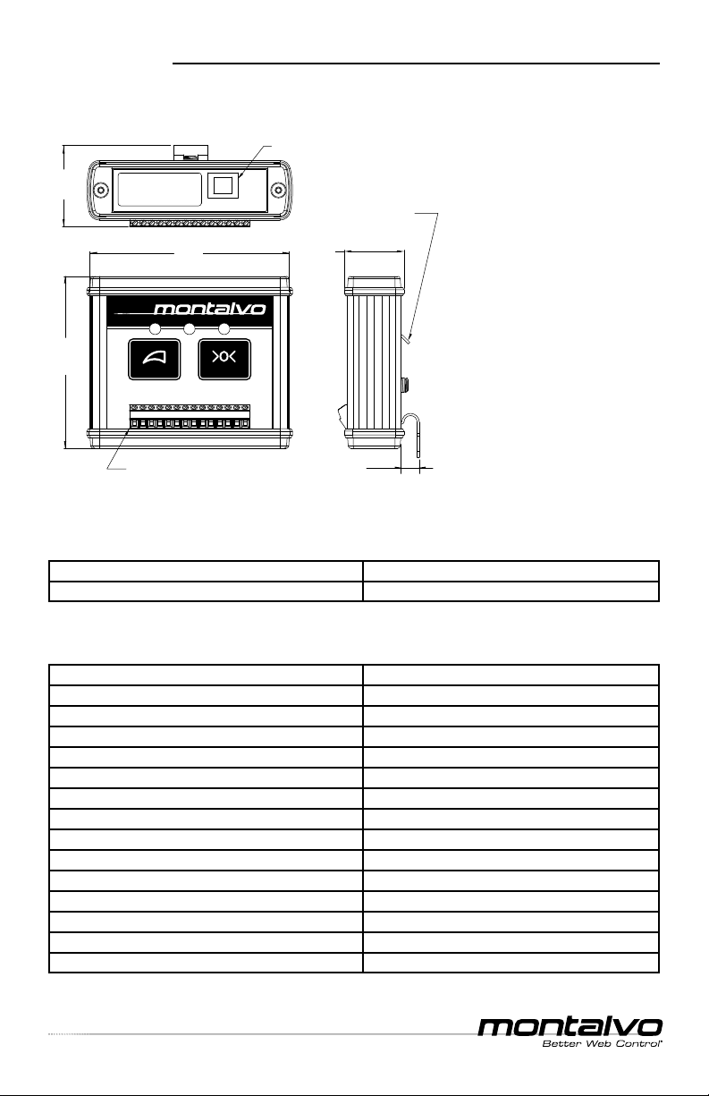
Dimensions ...............................................................................................3
Technical Data...........................................................................................3
Installation
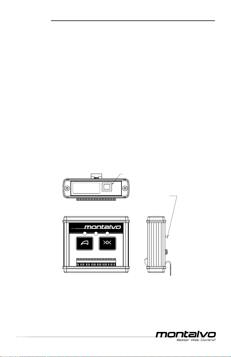
Mounting A4 .............................................................................................4
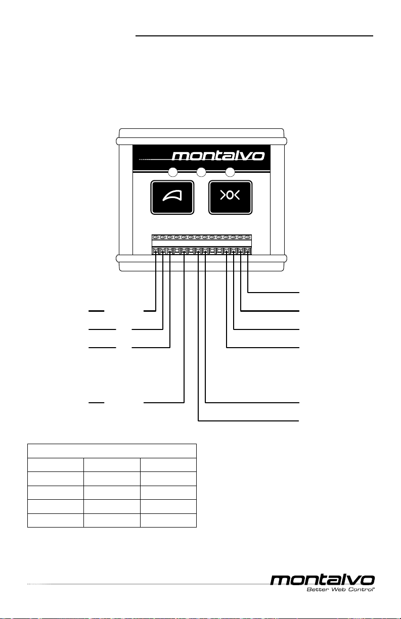
Connecting Power Supply.........................................................................5
Connecting Signal Output .........................................................................5
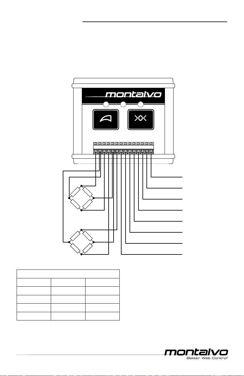
Connecting Load Cells
Dual Half Bridge Semiconductor Strain Gauge Load Cells.........................6
Single Full Bridge Semiconductor Strain Gauge Load Cells .......................7
Single Half Bridge Semiconductor Strain Gauge Load Cells ......................8
Dual Full Bridge Foil Gauge Load Cells......................................................9
Calibration (rmware v1.3 - starts w/ SN 306179)
Zero Point ...............................................................................................10
Calibration ..............................................................................................10
Keypad Lockout (rmware v1.3 - starts w/ SN 306179)
Introduction.............................................................................................11
Locking the Keypad ................................................................................11
Unlocking the Keypad .............................................................................11
Blinking Codes (rmware v1.3 - starts w/ SN 306179)
Introduction.............................................................................................12
Descriptions............................................................................................12
Digital Amplier Utility
Overview.................................................................................................14
Downloading / Installation .......................................................................15
Screen Descriptions ................................................................................16
Calibration...............................................................................................26
Password................................................................................................26
Filtering ...................................................................................................26
Troubleshooting
Software .................................................................................................27
Hardware ................................................................................................27

EST
.
1947
A4 Digital Amplier
__ ___________________________________________________________________________________
Technical Manual
p. 3
www.montalvo.com / Technical details subject to change without notice. A4-technical manual-US © Montalvo
SPECIFICATIONS
1234567891011121314
CAL ZERO
A4
Digital Amplier
1 : +Ex
2 : Sig
3 : -Ex
4 : +Ex
5 : Sig
6 : -Ex
7 : TOTAL 4-20mA
8 : TOTAL 0-10V
9 : LEFT 0-10V
10 : RIGHT 0-10V
11 : GND
12 : +24 VDC
13 : GND
14 : GND
}
Left Load Cell
}
Right Load Cell
}
Input
SN:
2.78
(70.6)
3.23
(82)
14 pin connector
screw terminal
0.97
(24.5)
0.30
(7.5)
DIN RAIL mount
EN-50035
1.31
(33.4)
USB type B
}
Output
Proportional
To Tension
Dimensions
Supply Voltage 24VDC
Overvoltage Category III (IEC 66-4)
Load Cell Input Range ±50mV / ±250 mV
Load Cell Supply 5 VDC ±1%
Gain Adjustment 11 to 510
Maximum Power Consumption 3.5VA
Maximum Power Supply Fuse 10A
Connector 14 pin / screw
Communications Connector USB Type B
Mounting Type DIN Rail EN-50035
Mounting Orientation Not Critical
Temperature-Operating +14 to +122ºF (-10 to +50ºC)
Temperature-Storage +14 to +176ºF (-10 to +80ºC)
Humidity <95% Non-Condensing
Degree of Protection IP20 (IEC 529)
A4 #11000601 Semiconductor Strain Gauge Type
A4 #11000859 Foil Gauge Type
Technical Data
Load Cell Compatibility

EST
.
1947
p. 4
www.montalvo.com / Technical details subject to change without notice. A4-technical manual-US © Montalvo
A4 Digital Amplier
__ ___________________________________________________________________________________
Technical Manual
INSTALLATION
Mounting A4
1The A4 should be mounted in a suitable cabinet for maximum protection,
however it may be installed just about anywhere for convenience. Avoid
dusty or wet locations.
2Mount the A4 to a standard 35mm DIN rail section (EN-50035).
3Ground the A4 using either terminal 11 or 14.
4If the A4 is to be used in conjunction with PC for setup and monitoring,
make sure to provide cable/plug access to the USB port which is located
on the top.
1234567891011121314
CAL ZERO
A4
Digital Amplier
SN:
35mm
DIN RAIL mount
EN-50035
USB type B

EST
.
1947
A4 Digital Amplier
__ ___________________________________________________________________________________
Technical Manual
p. 5
www.montalvo.com / Technical details subject to change without notice. A4-technical manual-US © Montalvo
INSTALLATION
Connecting Power Supply
1Connect 24VDC 3 wire power supply to terminals 12 (+24V), 13 (0V) using
either 11 or 14 as GND.
2Make sure to provide current overload protection.
Connecting Signal Output
1Connect meters such as Montalvo’s analog M4, digital meters or a PLC to
OUTPUT terminals 7 thru 10 as desired. Note: Depending on the load cells
` used, the Left (terminal 9) and the Right (terminal 10) outputs may not be
available.
1234567891011121314
CAL ZERO
A4
Digital Amplier
(14) GND
(13) OV
(12) +
24V
(11) GND
(10) Right 0 to 10V
(9) Left 0 to 10V
(8) Total 0 to 10V
(7) Total 4 to 20mA
Power Supply INPUT
Signal OUTPUT

EST
.
1947
p. 6
www.montalvo.com / Technical details subject to change without notice. A4-technical manual-US © Montalvo
A4 Digital Amplier
__ ___________________________________________________________________________________
Technical Manual
CONNECTING LOAD CELLS
1234567891011121314
CAL ZERO
A4
Digital Amplier
+
Excitation (1)
Left Signal (2)
-
Excitation (3)
-
Excitation (4)
Right Signal (5)
+
Excitation (6)
BN or RD
WH
BK
BN or RD
WH
BK
(14) GND
(13) OV
(12) +
24V
(11) GND
(10) Right 0 to 10V
(9) Left 0 to 10V
(8) Total 0 to 10V
(7) Total 4 to 20mA
RIGHT Load Cell
LEFT Load Cell
Standard conductor colors for Montalvo load cell cables
4 pin connector 6 pin connector 3 pin connector
Brown (BN) Red (RD) Red (RD)
White (WH) White (WH) White (WH)
Black (BK) Black (BK) Black (BK)
Blue (BU) Green (GN) -
Wiring for Montalvo ES / U/ DRD / DRC*Series Load Cells
• Dual Half Bridge Semiconductor Strain Gauge load cells
• Requires A4 Amplier #11000601
* DRC load cells are standard as Full bridge with Half bridge as an option.

EST
.
1947
A4 Digital Amplier
__ ___________________________________________________________________________________
Technical Manual
p. 7
www.montalvo.com / Technical details subject to change without notice. A4-technical manual-US © Montalvo
CONNECTING LOAD CELLS
1234567891011121314
CAL ZERO
A4
Digital Amplier
+
Excitation (1)
+
Signal (2)
-
Excitation (3)
-
Signal (5)
BN or RD
WH
BK
BU or GN
(14) GND
(13) OV
(12) +
24V
(11) GND
(8) Total 0 to 10V
(
7
)
Total 4 to 20mA
LEFT Load Cell
Standard conductor colors for Montalvo load cell cables
4 pin connector 6 pin connector 3 pin connector
Brown (BN) Red (RD) NA
White (WH) White (WH) NA
Black (BK) Black (BK) NA
Blue (BU) Green (GN) NA
Wiring for Montalvo N/ X/ TSR / N-Micro Series Load Cells
• Single Full Bridge Semiconductor Strain Gauge load cells
• Requires A4 Amplier #11000601

EST
.
1947
p. 8
www.montalvo.com / Technical details subject to change without notice. A4-technical manual-US © Montalvo
A4 Digital Amplier
__ ___________________________________________________________________________________
Technical Manual
CONNECTING LOAD CELLS
1234567891011121314
CAL ZERO
A4
Digital Amplier
+
Excitation (1)
Left Signal (2)
-
Excitation (3)
BN or RD
WH
BK
(14) GND
(13) OV
(12) +
24V
(11) GND
(8) Total 0-10V
(7) Total 4 TO 20mA
LEFT Load Cell
100Ω resistor (4)
(5)
100Ω resistor (6)
Standard conductor colors for Montalvo load cell cables
4 pin connector 6 pin connector 3 pin connector
Brown (BN) Red (RD) Red (RD)
White (WH) White (WH) White (WH)
Black (BK) Black (BK) Black (BK)
Blue (BU) Green (GN) -
Wiring for Montalvo ES / U/ DRD / DRC*Series Load Cells
• Single Half Bridge Semiconductor Strain Gauge load cell
• Requires A4 Amplier #11000601
* DRC load cells are standard as Full bridge with Half bridge as an option.

EST
.
1947
A4 Digital Amplier
__ ___________________________________________________________________________________
Technical Manual
p. 9
www.montalvo.com / Technical details subject to change without notice. A4-technical manual-US © Montalvo
Standard conductor colors for Montalvo load cell cables
4 pin connector 6 pin connector 3 pin connector
Brown (BN) Red (RD) Red (RD)
White (WH) White (WH) White (WH)
Black (BK) Black (BK) Black (BK)
Blue (BU) Green (GN) -
CONNECTING LOAD CELLS
Wiring for Montalvo LP Series Load Cells
• Dual Full Bridge Foil Gauge load cells
• Montalvo LP Full Bridge Foil Gauge load cells require A4 Amplier #11000859
• A4 is not compatible with Dual Full Bridge Semiconductor Stain Gauge load cells
* Montalvo LP load cells may require swapping excitation connections to
terminals 4& 6to generate a positive signal, depending on connector position
and/or load cell mounting position/orientation.
Dual Montalvo LP Load Cells using
Standard Montalvo Cables:
Conductor Color to A4 Terminal #s
WH both to terminal 2
BU both to terminal 5
BN left to terminal 1 and right to 4*
BK left to terminal 3 and right to 6*
1234567891011121314
CAL ZERO
A4
Digital Amplier
+
Excitation (1)
Left Signal (2)
-
Excitation (3)
+
Excitation (4*)
Right Signal (5)
-
Excitation (6*)
(14) GND
(13) OV
(12) +
24V
(11) GND
(10) Not Available
(9) Not Available
(8) Total 0-10V
(7) Total 4 to 20mA
RIGHT Load Cell
LEFT Load Cell
T
T
C
C
T
T
C
C
(5)
(4*)
(6*)
(3)
(5)
(1)
(2)
(2)

EST
.
1947
p. 10
www.montalvo.com / Technical details subject to change without notice. A4-technical manual-US © Montalvo
A4 Digital Amplier
__ ___________________________________________________________________________________
Technical Manual
CALIBRATION
Zero Point
1Connect the load cells to the A4 as described in the WIRING section.
2Apply power to the A4 and let it warm up for at least 10 minutes.
3With web removed and no tension on the load cell roller, press the ZERO
button on the A4 and hold it until the LED above the button ashes green.
When the zero point on the A4 is calibrated, it will automatically adjust the full
scale value to keep the measurement range the same as it was prior to the new
calibration.
Calibration
1Select a weight that is 20% of the maximum load expected to be present
on the load cells. If desired, the Windows application can be used to pick
a different percentage of total weight. This is particularly useful in
applications where a 20% weight is much too large to be practical.
2Suspend the chosen weight from a rope that has been fed through the
rollers of the machine exactly as the feed material will be in the application.
It is important that the rope match the wrap angles on the roller that will be
used when the machine is running.
3Spin all of the rollers the rope wraps around in the direction of the weight.
This is done to counteract friction forces on the rope from the rollers, which
will cause inaccurate readings.
4Press and hold the CAL button on the A4 until the LED above it ashes
green. Alternatively, the windows app can be used to set the full scale.
Resetting the A4 to factory default settings
See TROUBLESHOOTING page 27.
Known
Weight
Rope fastened
to this roller
Load Cell
Roller

EST
.
1947
A4 Digital Amplier
__ ___________________________________________________________________________________
Technical Manual
p. 11
www.montalvo.com / Technical details subject to change without notice. A4-technical manual-US © Montalvo
KEYPAD LOCKOUT (rmware v1.3 only)
Introduction
The A4 has a feature which allows for the keypad of the A4 to be locked out
in order to keep calibration values from being mistakenly changed. When the
keypad is in lockout mode, the LEDs on the face of the amplier will ash green
whenever a button is pushed. While in lockout mode, the buttons of the face of
the A4 will have no effect on the stored calibration values.
Locking the keypad
In order to lock the A4 keypad, press and hold both of the buttons on the face
of the amplier at the same time for 5 seconds. When the keypad is locked all
of the LEDs on the face of the A4 will ash simultaneously 5 times, indicating
the lockout was successful.
Unlocking the keypad
In order to unlock the A4 keypad, press and hold both of the buttons on the
face of the amplier at the same time for 5 seconds. When the keypad is
unlocked all of the LEDs on the face of the A4 will ash simultaneously 5 times,
indicating the lockout has been removed.

EST
.
1947
p. 12
www.montalvo.com / Technical details subject to change without notice. A4-technical manual-US © Montalvo
A4 Digital Amplier
__ ___________________________________________________________________________________
Technical Manual
BLINKING CODES (rmware v1.3 only)
Introduction
The A4 has a collection of blink codes
programmed into it that are represented
by blinking the three LEDs on the face of
the amplier in a particular pattern. These
codes are used to indicate the status of
the A4 and can be useful in determining
when there is a problem in the setup or
operation of the device.
Descriptions
Center LED steady GREEN
No Error - This is the status displayed during normal operation.
Center LED blinks RED 1 time every 2 seconds
Out of range on terminal 2 load cell - The tension reading for the load cell connected to
terminal 2 is not within the max./min. tension range determined during calibration. It is possible
that this error will be displayed momentarily during machine starts. If the error does not reset
itself within a few seconds, it is recommended to recalibrate the A4 for a wider max./min. range.
Center LED blinks RED 2 times every 2 seconds
Out of range on terminal 5 load cell - The tension reading for the load cell connected to
terminal 5 is not within the max./min. tension range determined during calibration. It is possible
that this error will be displayed momentarily during machine starts. If the error does not reset
itself within a few seconds, it is recommended to recalibrate the A4 for a wider max./min. range.
Center LED blinks RED 3 times every 2 seconds
Out of range on both load cells - The tension readings for both of the load cells
connected to the A4 are not within the max./min. tension range determined during calibration. It
is possible that this error will be displayed momentarily during machine starts. If the error does
not reset itself within a few seconds, it is recommended to recalibrate the A4 for a wider
max./min. range.
All LEDs blink GREEN in alternating pattern 5 times
Keypad locked out - When a button on the A4 is pressed and the keypad is currently
locked out, the lights will ash green to indicate that the lockout must be released before a
change can be made. To release keypad lockout, hold down both of the buttons on the face of
the A4 for 5 seconds.
1234567891011121314
CAL ZERO
A4
Digital Amplier
GREEN GREENGREEN
or
RED

EST
.
1947
A4 Digital Amplier
__ ___________________________________________________________________________________
Technical Manual
p. 13
www.montalvo.com / Technical details subject to change without notice. A4-technical manual-US © Montalvo
BLINKING CODES (rmware v1.3 only)
All LEDs blink GREEN simultaneously 5 times
Keypad lockout acknowledged - Locking out the keypad on the A4 is a good way to
keep someone from mistakenly changing either the full scale or zero calibration points. To lock
out the keypad, hold down both of the buttons on the face of the A4 for 5 seconds. After the
blink pattern nishes, pressing either of the buttons will have no effect until the lockout condition
is turned off.
Center LED steady RED and CAL LED blinks GREEN 2 times every 2 seconds
Full scale calibration / Weight too large - This error is generated when calibration
weight is too large. This error is cleared by holding down the [CAL] button for a few seconds.
Reduce the weight and try again.
Center LED steady RED and CAL LED blinks GREEN 4 times every 2 seconds
Full scale calibration (Reversed action) - This error is generated when terminal
connections for the A4 are backwards or the load cells are mounted incorrectly. Make sure wires
at terminals 2 and 5 aren’t reversed; additionally, check that polarity of wires at terminals 1 and
3 (as well as 4 and 6) are correct. Check that the load direction on the load cells is correct and
that they produce a positive output when force is applied in the intended positive direction. This
error is cleared by holding down the [CAL] button for a few seconds.
Center LED steady RED and CAL LED blinks GREEN 5 times every 2 seconds
Full scale calibration (Missing zero point) - This error is generated when there is no
zero point programmed into the A4 from which the full scale can be calculated. This error is
cleared by holding down the [CAL] button for a few seconds. Re-zero the A4 and then calibrate.
Center LED steady GREEN and CAL LED blinks GREEN 3 times
Full scale calibration (Calibration good) - This blink code is generated when the full
scale calibration has completed successfully.
Center LED steady RED and CAL LED ashes GREEN 2 times every 2 seconds
Zero calibration (Calibration value over range) - This error is generated when the
new zero set-point will cause the maximum tension value of the amplier to go beyond the range
of the possible values. Even though an error is generated, the zero point for the amplier will be
updated to the new calibration value. This error is cleared by holding down the [ZERO] button for
a few seconds. To x this issue, recalibrate the A4.
Center LED steady RED and ZERO LED ashes GREEN 4 times every 2 seconds
Zero calibration (calibration failed) - This error is generated any time there is a problem
with the zero calibration attempt. Even though an error is generated, the zero point for the
amplier will be set to the new zero value. To x this error, ensure that load cells are connected
correctly, that the machine is idle, and attempt to zero the A4 again. This error is cleared by
holding down the [ZERO] button for a few seconds.

EST
.
1947
p. 14
www.montalvo.com / Technical details subject to change without notice. A4-technical manual-US © Montalvo
A4 Digital Amplier
__ ___________________________________________________________________________________
Technical Manual
DIGITAL AMPLIFIER UTILITY
Overview
Montalvo’s Digital Amplier Utility is a free app to assist in performing important
tasks at setup and during operation and provides critical feedback for optimum
productivity. Utilize the integrated USB port to connect the A4 directly to a
computer to remotely calibrate and graphically monitor both raw inputs from
the load cells and amplier outputs.
Features
• Sensor Calibration
• Output Calibration
• Tension Monitoring
• Alerts
Use the link below to download your free copy now:
https://www.montalvo.com/products/a4-digital-amplier/

EST
.
1947
A4 Digital Amplier
__ ___________________________________________________________________________________
Technical Manual
p. 15
www.montalvo.com / Technical details subject to change without notice. A4-technical manual-US © Montalvo
DIGITAL AMPLIFIER UTILITY
Download / Installation
1Connect the A4 amplier to a 24 VDC power supply at pins 12 (+24V) and
13 (0V).
2Connect the A4 to a PC using a USB cable.
3Navigate to the location on the C drive where the A4 software is located.
4Click on the setup.exe le to install the application.
5A dialog window will open asking if you want to install the application. Click
the [INSTALL] button.
6Once the application has nished installing, the device selection window
should appear (see below).
7Select the desired A4 (there should only be one choice unless multiple A4s
are connected to the PC) and click the [CONNECT] button.

EST
.
1947
p. 16
www.montalvo.com / Technical details subject to change without notice. A4-technical manual-US © Montalvo
A4 Digital Amplier
__ ___________________________________________________________________________________
Technical Manual
DIGITAL AMPLIFIER UTILITY
Monitor Window
This window is used to monitor the current status of the A4. It graphs the
output channels of the device as well as displaying details about the connected
A4’s rmware revision, sensor type and serial number.
Key Elements
1The [RE-DISCOVER] will detect if there are any A4 devices connected
to the computer and allow the user to select one to interact with through
the GUI (if there are multiple units connected).
2The [ABOUT] button just lists details about the software and A4 unit.
3The [KEYPAD LOCK] button will lock the controls on the A4 so that the
push buttons on the device itself will not have any effect. When the keypad
is locked out, the button will turn red, and will be green when the buttons
aren’t locked out.
4The [ACTIVATE] button will unlock the Analog Output Calibration tab when
the correct password is entered. The password is: Montalvo2010.

EST
.
1947
A4 Digital Amplier
__ ___________________________________________________________________________________
Technical Manual
p. 17
www.montalvo.com / Technical details subject to change without notice. A4-technical manual-US © Montalvo
1Re-Discover 2About 3Keypad Lock 4Activate
DIGITAL AMPLIFIER UTILITY
Monitor Tab

EST
.
1947
p. 18
www.montalvo.com / Technical details subject to change without notice. A4-technical manual-US © Montalvo
A4 Digital Amplier
__ ___________________________________________________________________________________
Technical Manual
DIGITAL AMPLIFIER UTILITY
Conguration Window
The /Conguration/ window is used to view the A4 devices serial number and
set the ltering options available to the user.
Deadband
The deadband in the A4 is used to lter out noise on an idle roll. Essentially, it
will treat any signal below the set percentage as though it were 0. It is important
to keep the deadband value set low, particularly for signals that might not be
particularly large to begin with. Between 0 to 2% should be a good range for
the deadband.
In applications that use shallow wrap angles and / or over-sized load cells, it’s
important that the deadband be kept within the recommended range. Using
values outside this range in these applications can cause performance issues
with PID controllers.
Exponential Filter
The A4 rmware has a simple, congurable exponential lter. The user is able to
customize the lter behavior by adjusting the alpha value in the lter. Values for
alpha should be between 0 and 1. A value closer to 0 will more heavily weight
past measurements (more heavily lter the signal) while a value of 1 will place
all of the weight on the most recently taken sample (essentially no lter). The
default value for alpha should be 0.7, offering some light ltering. The behavior
of the lter is given by:
Signal = (alpha * samplepresent ) + (1 - alpha) * Signalpast
Where Signal is the output from the A4, sample is the current measurement
from an attached load cell, Signalpast is the weighted value from previous
sampling and alpha is the scaling factor that determines the weighting between
the most recent sample and past samples.
Key Elements
1Display of the serial number for the A4 currently connected to the PC.
2The [Read Values] button will read the current value for both the deadband
and exponential lter settings in the A4.
3The [Set Values] button will set the values of both the deadband and the
alpha value of the lter. The deadband value should be kept to a small
fraction of the total signal (0 to 2%) for best results. The alpha value should
be between 0 and 1.
4When reading back values stored in the A4, the percentages won’t
perfectly match the values that were entered. This is normal, and a result of
the way the A4 stores numbers.

EST
.
1947
A4 Digital Amplier
__ ___________________________________________________________________________________
Technical Manual
p. 19
www.montalvo.com / Technical details subject to change without notice. A4-technical manual-US © Montalvo
DIGITAL AMPLIFIER UTILITY
1Serial Number 2Read Values 3Set Values
Conguration Tab

EST
.
1947
p. 20
www.montalvo.com / Technical details subject to change without notice. A4-technical manual-US © Montalvo
A4 Digital Amplier
__ ___________________________________________________________________________________
Technical Manual
DIGITAL AMPLIFIER UTILITY
Sensor Calibration Window
The Sensor Calibration window is used to set up the zero point and full scale,
as well as the ratios used to calculate those values. The procedure for setting
the full scale is describing in Calibration / Full Scale. The user can calibrate
the A4 either using the GUI or the buttons on the face of the A4. Using the GUI
allows for a few more options in setting up the calibration, but works in the
same manner otherwise.
Key Elements
1Cal Units is used to describe the weight being used to calibrate the A4.
It exists as a convenience for the user, and does not necessarily need to
be set in order to calibrate the A4 (If you know the weight values in kg,
but the ‘Cal Units’ is set to lbs, it will work just ne). The Desired Full Scale
eld should be set to the maximum weight that the load cells are going to
measure. The Calibration Value eld is the weight that is being hung as part
of the calibration procedure, and allows the A4 to calculate the full scale
range.
2The [SAVE CALIBRATION PARAMETERS] button will save the input values
for Cal Units, Desired Full Scale and Calibration Value. This is useful in the
case of wanting to use a different ratio between desired full scale and
calibration value than what is programmed into the A4 by default. Do not
click this button to save these changes unless you are ready to use
these values and to perform a complete zero and full scale calibration
per page 10.
3The [SET DEFAULTS] button is used to reset the calibration values of the
A4 to factory defaults.
4The [APPLY ZERO] button will set the A4’s zero point at whatever the
current weight present on the load cell when the button is pressed.
Pressing this button is synonymous with pressing the [ZERO] button on the
A4 itself.
5The [APPLY FULL SCALE] button will calculate the full range of
measurement for the A4 based on the ratio between the Desired Full Scale
and the calibration weight being used. Pressing this button is synonymous
with pressing the [CAL] button on the A4 itself.
This manual suits for next models
2
Table of contents
Other Montalvo Amplifier manuals