8/1/02
© 2002 Montalvo
Applications:
The M3200-ce module is used with semiconductor-
gauge tension roller assemblies to indicate the exact
web tension on process machines such as slitters, coat-
ers, rewinders, embossers, and printing and label
presses.
Adjustment procedure:
1. Check that tension sensing roller is mounted cor-
rectly.
2. A remote tension meter can be used to calibrate the
module. If used, check that meter is adjusted to
zero mechanically.
3. In the event that a remote meter is not used, a volt-
meter is required. Connect voltmeter between ter-
minals 13 (+) and 15 (-).
4. With the web removed and no tension applied to the
tension sensing roller, adjust ZERO until either 0V
is measured on Total output (13) or the remote
meter reads zero.
5. Thread a rope across the center of the tension sens-
ing roller following the path of the web through the
machine. Thread the rope at least one roller before
and one roller after the tension sensing roller.
Insure that rope does not pass over any deadbars or
non-freewheeling rolls. All rollers in contact with
the rope must be able to rotate freely. Fasten one
end of the rope securely, attaching a weight of
known value to the other end. This weight should
be at least 25% of the full scale value. Rotate roll-
ers in the direction of the weight.
6. Adjust CAL. until remote tension meter displays
the calibration weight. If using a voltmeter, adjust
until Total output voltage displays a value calcu-
lated by the following formula:
V=(cal. weight/CAL. full-scale value) x 10 volts
Note: A negative meter reading after the hanging
of the weight indicates that the signals from the
load cells are reversed. In the event of a negative
reading, switch the wires between terminals 10 and
11.
7. Remove weight and check that outputs return to 0.
If not, repeat steps 3 through 6.
Alarm level adjustment:
Apply a weight to the tension sensing roller equal to
the value that should activate the alarm. Adjust
ALARM potentiometer until ALARM LED lights up.
Alarm output will be high (+24 V) whenever tension
drops below the alarm level.
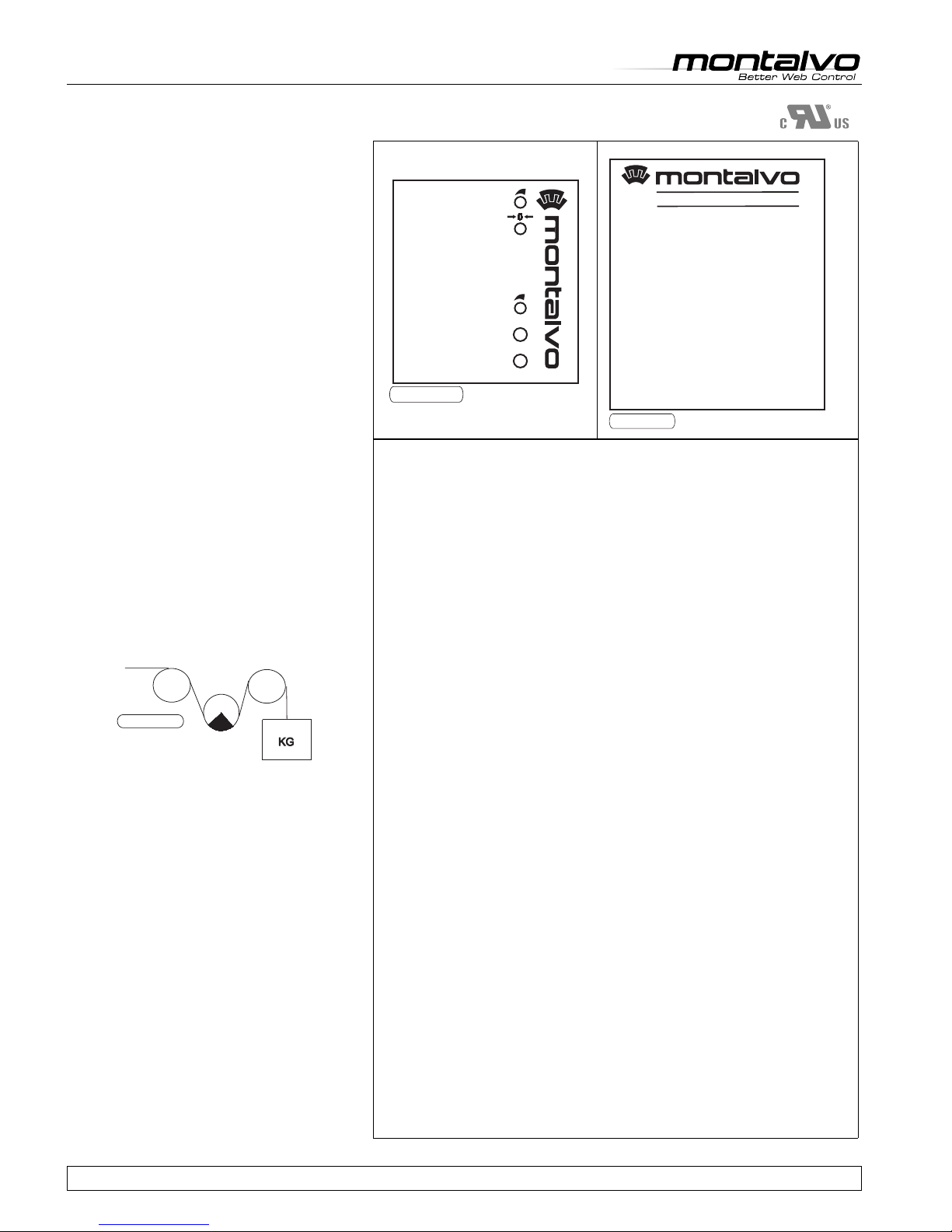
Load cell
PR011.eps
Load Cell Amplifier M3200-ce
Electrical specifications:
Supply Voltage, Selectable ..................................... 115V/230V AC ± 10% (IEC 204-1)
Supply Frequency...............................................................................................48-62 Hz
Overvoltage Category................................................................................... II (IEC 664)
Maximum Internal Fuse Size ........................ 5x20mm 115V/80mA(T)/230V/50mA(T)
Material Degree of Inflammability..................................................................... UL94V0
Maximum Power Consumption ........................................................................... 3.5 VA
Maximum Supply Fuse Size ....................................................................................10 A
Testing Voltage - Primary to Secondary......................................... 3.75 kV for 1 Minute
EMC-Immunity ..............................................................................EN 50082-2, Industry
EMC-Emission .................................................... EN 50081-1, Trade and Light Industry
Degree of Protection................................................................................ IP20 (IEC 529)
Installation Environment (Pollution Degree) .................................................................2
Connections ......................................................................... Removable Terminal Blocks
Weight ................................................................................................. 0.14 lbs. (0.3 kg)
Dimension (L x W x H) .....................................2.95 x 1.77 x 4.21 (75 x 45 x 107 mm)
Mounting .............................................................................................. DIN Rail 35 mm
Mounting Orientation....................................................................................Not Critical
Ambient Temperature Range: Operating ........................ 14°F to 122°F (-10°C to 50°C)
Ambient Temperature Range: Storing............................. 14°F to 176°F (-10°C to 80°C)
Humidity ...................................................................................... 95% Non-Condensing
Load Cell Input ........................................................................................... .±250mVDC
Input Impedance .................................................................................................100 KΩ
Load Cell Supply ................................................................................... ±2.5 VDC ±2%
Meter Output, Selectable.................................. 0 to 100µA / 0 to10V, Max. Load 5 mA
Process Output, Selectable .................................... 0 to 20 mA / 4 to 20 mA / 0 to 10V
Process Output Load (Current)........................................................................... .≤500 Ω
Process Output Load (Voltage).......................................................................... > 5000 Ω
Zero Range Adjustment ........50% of Load Cell Rating [Max. 250m VDC (±125 mV)]
Gain Adjustment ..............................................................................................11 to 510
Accuracy ................................................................................................ Better Than 1%
Alarm Output Voltage ..............................................................................24 VDC ±15%
Alarm Output Load ............................................................................................. > 650 Ω
CAL.
ALARM
ALARM
POWER
ZERO
IL077.eps
1:
2:
3:
4:
5:
6:
7:
8:
9:
10:
11:
12:
13:
14:
15:
16:
Ground PE
Line L
Line N
Ground
NC.
+2.5V Supply
+ input +/- 250mV
- input +/- 250mV
-2.5V Supply
Total output 0-10V / 0-100 A
Total output 4-20 mA / 0-20 mA/ 0-10V
Ground
Alarm output
NC.
M3200 LOAD CELLAMPLIFIER
IL053.eps


