EST
.
1947
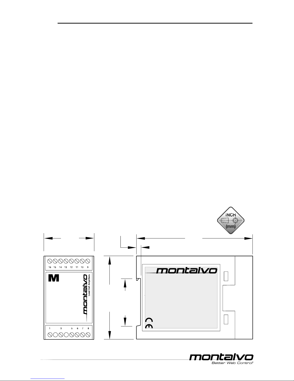
M Series Amplier
__ ___________________________________________________________________________________
Technical Manual
p. 9
www.montalvo.com / Technical details subject to change without notice. Mamp-technical manual-US-07 © Montalvo
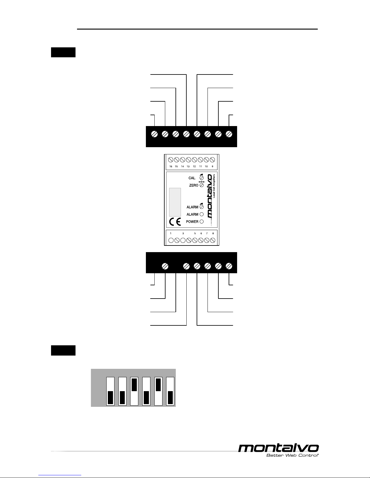
WIRING
(15) Ground (0V DC)
(12) - 2.5V Supply (excitation)
(11) Left - Input ± 250mV (signal)
(10) Right + Input ± 250mV (signal)
(9) + 2.5V Supply (excitation)
BK WH BN
or
RD
16 15 14 13 12 11 10 9
BK WH BN
or
RD
#1 (LEFT)
Load Cell
#2 (RIGHT)
Load Cell
(15) Ground (0V DC)
(12) - 2.5V Supply (excitation)
(11) Left - Input ± 250mV (signal)
(10) Right + Input ± 250mV (signal)
(9) + 2.5V Supply (excitation)
BK WH BN
or
RD
BL
or
GN
16 15 14 13 12 11 10 9
#1 (LEFT)
Load Cell
BK WH BN
or
RD
BL
or
GN
#2 (RIGHT)
Load Cell
(15) Ground (0V DC)
(12) - 2.5V Supply (excitation)
(11) Left - Input ± 250mV (signal)
(10) Right + Input ± 250mV (signal)
(9) + 2.5V Supply (excitation)
16 15 14 13 12 11 10 9
BK WH BN
or
RD
BL
or
GN
Load Cell
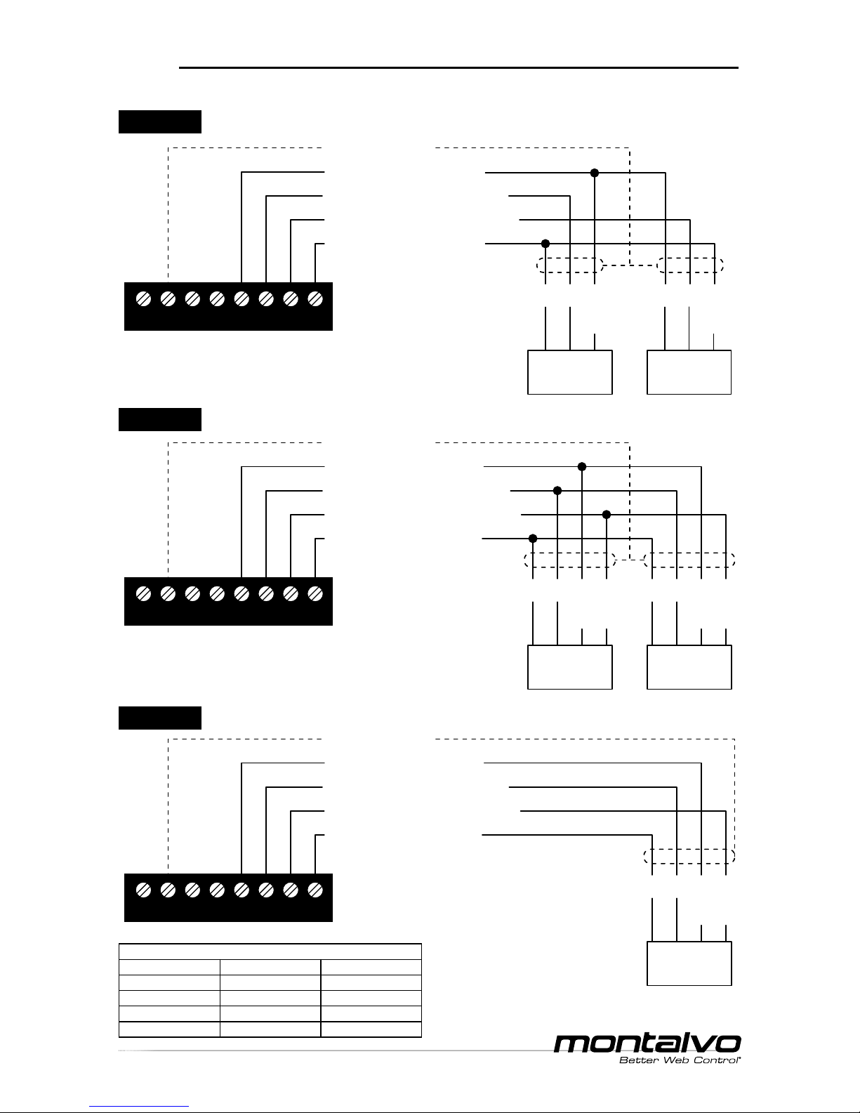
*If using only a single half bridge load cell,
connect as shown for #2 load cell.
M3200LTR Dual* Half Bridge Semiconductor Strain Gauge Load Cells
M3200LTR Dual Full Bridge Semiconductor Strain Gauge Load Cells
M3200LTR Single Full Bridge Semiconductor Strain Gauge Load Cell
Standard conductor colors for Montalvo load cell cables
4 pin connector 6 pin connector 3 pin connector
Brown (BN) Red (RD) Red (RD)
White (WH) White (WH) White (WH)
Black (BK) Black (BK) Black (BK)
Blue (BU) Green (GN) NA