Montarbo TP-1 User manual

MANUALE D’USO - SEZIONE 1
USER MANUAL - SECTION 1
BEDIENUNGSANLEITUNG - ABSCHNITT 1
NOTICE D’EMPLOI - SECTION 1
MANUAL DE USO - SECCIÓN 1
1
PREAMPLIFICATORE VALVOLARE
TUBE PREAMP
RÖHREN-VORVERSTÄRKER
PRÉAMPLIFICATEUR À VALVE
PREAMPLIFICADOR VALVULAR

TP-11
32
ITA
manuale d’uso
Grazie per aver acquistato un prodotto Montarbo, azienda italiana fondata nel 1962, da
sempre al servizio della musica e dell’audio professionale. I prodotti Montarbo, originali e
all’avanguardia, sono progettati con la massima attenzione ai dettagli e alla durevolezza
nel tempo. L’adabilità è in linea con gli alti standard qualitativi e la sensibilità all’impatto
ambientale che contraddistinguono l’azienda.
Il preamplicatore valvolare TP-11 permette di avere nel palmo di una mano un potente
strumento da utilizzare in studio o dal vivo. Le dimensioni compatte, il peso contenuto
e la costruzione robusta lo rendono perfetto per adattarsi a molteplici applicazioni,
anche in movimento. La valvola, centro del percorso di segnale interamente analogico,
è controllata da un encoder rotativo che offre ben 16 preset differenti per altrettanti
colori sonori da utilizzare sia per riprese microfoniche che per strumenti. Le connessioni
on-board permettono di collegare l’unità anche ad altre apparecchiature professionali.
AVVERTENZE
Le avvertenze del presente manuale devono essere osservate congiuntamente al “Manuale d’uso - sezione 2”.
Leggete il manuale prima dell’uso.
Conservate questo manuale a portata di mano per riferimenti futuri.
CONTENUTO DELLA CONFEZIONE
1 x preamplicatore valvolare
1 x alimentatore di corrente esterno 12V/2A
3 x spine elettriche due poli intercambiabili per prese US, UK, EU
1 x Manuale d’uso - Sezione 1
1 x Manuale d’uso - Sezione 2

TP-11
54
ITA
manuale d’uso
PANNELLO SUPERIORE
4 INPUT
Utilizzare questa manopola per controllare il livello del segnale in ingresso al
preamplicatore.
5 SELETTORE PRESET
Questo encoder a 16 posizioni permette di scegliere quale carattere imprimere al vostro
suono tramite la valvola.
6 OUT
Utilizzare questa manopola per controllare il livello del segnale in uscita dal
preamplicatore.
PANNELLO DI CONTROLLO
PANNELLO FRONTALE
1 PRESA INPUT
Ingresso combo per il collegamento delle sorgenti audio (microfoni o strumenti di linea)
tramite cavo jack da 6,35mm o cavo XLR.
2 SENS
Premere questo tasto per scegliere la sensibilità di ingresso:
- LINE: segnale di linea, condizioni di impiego più frequenti.
- MIC: segnale microfonico, microfono dinamico o a condensatore.
3 +48V
Questo tasto attiva l’alimentazione Phantom, prima di attivarla collegare il cavo del
microfono; disattivarla prima di scollegare il cavo. Vericare che il vostro microfono
necessiti dell’alimentazione +48V.
4
5
10
9
6
8
7
1
2 3

TP-11
76
ITA
manuale d’uso
7 INPUT LEVEL
Questo pulsante agisce come un comando PFL “pre-fader listening”. Quando è premuto
consente di vericare il livello di ingresso sul VU meter OUT/IN ed ottimizzare il guadagno
di conseguenza.
8 LEVELS
Indicatori a led dei livelli di IN/OUT e Gain Reduction:
- OUT/IN: nelle condizioni di impiego più frequenti, visualizza il livello del segnale in
uscita. Quando il pulsante INPUT LEVEL viene premuto visualizza il livello del segnale
in ingresso.
- GAIN REDUCTION: visualizza dall’alto verso il basso la riduzione del guadagno in
uscita.
9 LOW CUT
Questo selettore attiva (posizione On) e disattiva (posizione Off) il ltro passa alto.
10 POLARITY
Muovere questo selettore per invertire la fase del segnale (valore 180°).
PANNELLO RETRO
11 OUTPUT BAL
Collegare questa uscita bilanciata a un registratore, scheda audio, mixer tramite cavo
XLR bilanciato.
12 OUTPUT UNBAL
Collegare questa uscita sbilanciata a un amplicatore o processore esterno tramite
cavo jack sbilanciato.
13 DIRECT OUT
Uscita diretta del segnale non processato dal preamplicatore.
INPUTSENS
LINE MIC
+48V
ON
AEB INDUSTRIALE S.R.L.
Via Brodolini, 8 - Località Crespellano
40053 VALSAMOGGIA (BO) - ITALY
www.montarbo.com
SERIAL N.
This device complies with part 15 of the FCC Rules.
Operation is subject to the following two conditions: (1)
this device may not cause harmful interference, and (2)
this device must accept any interference received,
including interference that may cause undesired operation.
TUBE PREAMP
POWER BAL.
DC 12V/2A
I
N
S
E
R
T
D
I
R
E
C
T
O
U
T
UNBAL.
O
U
T
P
U
T
BAL.
O
U
T
P
U
T
“CAUTION”
RISK OF ELECTRICAL SHOCK
DO NOT OPEN
“AT TENTION”
RISQUE DE CHOCH ELECTRIQUE
NE PAS OUVRIR
1314 12
11
15

TP-11
98
ITA
manuale d’uso
14 INSERT
Questa presa jack stereo consente di collegare dispositivi esterni, per esempio un
compressore o un EQ, in grado di elaborare la dinamica del segnale.
Per il collegamento usare un cavo ad “Y” inserendo un connettore stereo così cablato:
punta (T) mandata, anello (R) ritorno, calza (S) massa comune, quindi collegare il
dispositivo esterno con due connettori sbilanciati, uno per l’ingresso ed uno per l’uscita.
15 POWER INPUT
Collegate qui l’alimentatore di corrente esterno fornito in dotazione.
CONSIGLI DI UTILIZZO
È consigliabile posizionare il preamplicatore su una supercie piana in un locale ben
areato facendo attenzione che i fori per il raffreddamento della valvola siano liberi e non
a contatto con alcuna supercie. Prima di collegare il cavo di alimentazione alla presa di
corrente ruotate le manopole Input e Out a -∞ e controllate che la phantom +48V sia in
posizione off. Alimentate quindi l’apparecchio e poi il cavo del microfono o strumento in
Input. Regolate le manopole di Input e Out in modo tale che sul VU meter il led CLIP si
accenda sui fortissimo musicali. Il selettore di preset centrale vi permette di utilizzare la
saturazione della valvola per colorare il suono della sorgente sonora in ingresso. Potete
scegliere tra 16 impostazioni differenti suddivise in:
COLD - per preservare il suono naturale dello strumento/voce in ingresso. Risposta
pressoché lineare e priva di importanti colorazioni tonali.
WARM - per enfatizzare la presenza dello strumento/voce in ingresso. Risposta con un
loudness più marcato e incisivo.
WARM + GAIN REDUCTION - Per tutte quelle situazioni in cui il segnale in ingresso è molto
forte e prossimo alla distorsione (effetto di prossimità o variazione di ampiezza del segnale
molto rapida). Risposta analoga ai preset WARM.
COLD + GAIN REDUCTION - Per tutte quelle situazioni in cui il segnale in ingresso è molto
forte e prossimo alla distorsione (effetto di prossimità o variazione di ampiezza del segnale
molto rapida). Risposta analoga ai preset COLD.
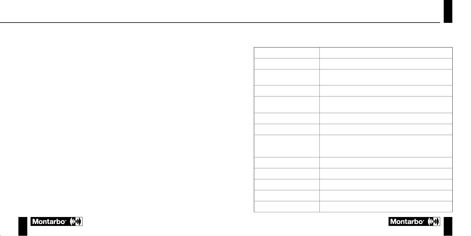
SPECIFICHE TECNICHE
Ingressi
Combo (XLR+jack), insert
Uscite
Uscita XLR bilanciata, uscita jack sbilanciata, direct out
Controlli
Manopola livello input, manopola livello output, selettore preset, low cut,
polarity, +48V, Line/Mic input sens
Impedenza in ingresso
(XLR-TS JACK)
2kΩ - 840kΩ
Impedenza in uscita
(XLR-TS JACK)
600Ω - 300Ω
Massimo livello in ingresso XLR
+15 dBu
Massimo livello in ingresso TS
+22 dBu
Massimo livello in uscita:
XLR
TS
+28 dBu
+22 dBu
CMRR
>75dB (tipico @ 1kHz)
Risposta in frequenza
10 Hz - 30 kHz (±6dB)
Filtro Low Cut
-12 dB@50 Hz
Range dinamico (20-20kHz)
>100 dBu (tipico)

TP-11
1110
ITA
manuale d’uso
SNR
90 dBu
Distorsione armonica totale
(THD)
>0,1% (tipico)
Gain massimo:
XLR In - XLR Out
XLR In - TS JACK Out
TS JACK In - XLR Out
TS JACK In - TS JACK Out
63 dBu (tipico)
57 dBu (tipico)
54 dBu (tipico)
48 dBu (tipico)
Rumore equivalente in ingresso:
da XLR a XLR
da TS JACK a TS JACK
-120 dBu (pesato A)
-90 dBu (pesato A)
Tipo di valvola
ECC83S, 12AX7 A.F. Doppio Triodo
Alimentazione
AC IN: 100-240V~
DC OUT: 12V/2A
fornito con tre spine elettriche due poli intercambiabili per prese US, UK, EU
Dimensioni (L x A x P)
133 x 113.2 x 62mm
Peso
600g
NOTES

TP-11
1312
ENG
User manual
Thank you for purchasing a product created by Montarbo, an Italian company founded in
1962, always at the service of music and professional audio. Montarbo products, original and
avant-garde, are designed with the utmost attention to detail and durability. Reliability is in
line with the high quality standards and sensitivity to environmental impact that distinguish
the company.
With the TP-11 tube preamp, you have in the palm of your hand a powerful tool for
use in the studio or in a live setting. Its compact dimensions, low weight and rugged
construction make it ideal for multiple applications, including mobile uses. The tube,
which lies at the centre of an entirely analogue signal pathway, is controlled by a rotary
encoder that offers a choice of 16 different presets providing an equal number of tonal
colours for microphones and instruments. The on-board connections allow the unit to be
connected to other professional sound equipment.
WARNINGS
The warnings in this manual must be observed in conjunction with the “User manual - Section 2”.
Read the manual before use.
Keep this manual close to hand for future reference.
PACKAGE CONTENTS
1 x tube preamp
1 x 12V/2A external power supply unit
3 x interchangeable 2-pin electrical plugs for US, UK and EU sockets
1 x User manual - Section 1
1 x User manual - Section 2

TP-11
1514
ENG
User manual
TOP PANEL
4 INPUT
Use this knob to control the level of the input signal to the preamp.
5 PRESET SELECTOR
This 16 position encoder enables you to choose the tonal characteristics applied to your
sound by the tube.
6 OUT
Use this knob to control the level of the output signal from the preamp.
CONTROL PANEL
FRONT PANEL
1 INPUT SOCKET
Combo input socket for connection of audio sources (microphones or line level
instruments) via 6.35 mm jack or XLR.
2 SENS
Press this switch to select the sensitivity of the input:
- LINE: line level signal, for most common situations of use.
- MIC: microphone signal, dynamic or condenser microphone.
3 +48V
Phantom power switch; connect the microphone cable before activating and disconnect
the cable before deactivating. Check if your microphone requires a +48V power supply.
4
5
10
9
6
8
7
1
2 3

TP-11
1716
ENG
User manual
7 INPUT LEVEL
This button acts as a pre-fader listening (PFL) control. When pressed, it enables you to
check the input level on the OUT/IN VU meter and optimise the gain accordingly.
8 LEVELS
LED indicators for IN/OUT and Gain Reduction levels:
- OUT/IN: in the most common situations of use, shows the level of the output signal.
When the INPUT LEVEL button is pressed, shows the level of the input signal.
- GAIN REDUCTION: displays the output gain reduction from the top to the bottom.
9 LOW CUT
This switch activates (On position) or deactivates (Off position) the high pass lter.
10 POLARITY
Operate this switch to reverse the phase of the signal (180°).
REAR PANEL
11 OUTPUT BAL
Connect this balanced output to a recorder, sound card or mixer via a balanced XLR
cable.
12 OUTPUT UNBAL
Connect this unbalanced output to an amplier or external processor via an unbalanced
jack cable.
13 DIRECT OUT
Direct output for the signal not processed by the preamp.
INPUTSENS
LINE MIC
+48V
ON
AEB INDUSTRIALE S.R.L.
Via Brodolini, 8 - Località Crespellano
40053 VALSAMOGGIA (BO) - ITALY
www.montarbo.com
SERIAL N.
This device complies with part 15 of the FCC Rules.
Operation is subject to the following two conditions: (1)
this device may not cause harmful interference, and (2)
this device must accept any interference received,
including interference that may cause undesired operation.
TUBE PREAMP
POWER BAL.
DC 12V/2A
I
N
S
E
R
T
D
I
R
E
C
T
O
U
T
UNBAL.
O
U
T
P
U
T
BAL.
O
U
T
P
U
T
“CAUTION”
RISK OF ELECTRICAL SHOCK
DO NOT OPEN
“AT TENTION”
RISQUE DE CHOCH ELECTRIQUE
NE PAS OUVRIR
1314 12
11
15

TP-11
1918
ENG
User manual
14 INSERT
This stereo jack socket allows you to connect external devices, such as a compressor or
EQ, for dynamic signal processing.
For connection, use a “Y” cable with a TRS stereo connector wired as follows:
tip (T) - send, ring (R) - return, sleeve (S) - common ground, then connect the external
device using two unbalanced connectors, one for the input and one for the output.
15 DC INPUT
Connect here the external power supply unit supplied with preamp.
RECOMMENDATIONS FOR USE
We recommend that the preamp is positioned on a flat surface in a well-ventilated room,
making sure that the valve cooling slots are unobstructed and not in contact with any
surfaces. Before connecting the power supply cable to the power input socket, turn the
Input and Out knobs to -∞ and check that +48V phantom power is switched off. Power
on the preamp and then connect the microphone or instrument cable to the Input socket.
Adjust the Input and Out knobs so that the CLIP LED on the VU meter lights up with very
loud signals. The central preset selector allows you to control the level of tube saturation
to colour the sound of the input source. You can choose from 16 different settings divided
into the following:
COLD - to retain the natural sound of the input instrument/voice. Almost linear response
without any signicant tonal colouration.
WARM - to emphasize the presence of the input instrument/voice. Response with enhanced,
more incisive loudness.
WARM + GAIN REDUCTION - For situations where the input signal is very loud and close to
distortion (effect of proximity or very rapid changes in signal amplitude). Response similar
to WARM presets.
COLD + GAIN REDUCTION - For situations where the input signal is very loud and close to
distortion (effect of proximity or very rapid changes in signal amplitude). Response similar
to COLD presets.
TECHNICAL SPECIFICATIONS
Inputs
Combo (XLR+jack), insert
Outputs
Balanced XLR output, unbalanced jack output, direct out
Controls
Input level knob, output level knob, preset selector, low cut switch, polarity
switch, +48V switch, Line/Mic input sens
Input impedance (XLR-TS JACK)
2kΩ - 840kΩ
Output impedance (XLR-TS
JACK)
600Ω - 300Ω
Maximum input level XLR
+15 dBu
Maximum input level TS
+22 dBu
Maximum output level:
XLR
TS
+28 dBu
+22 dBu
CMRR
>75dB (typical @ 1kHz)
Frequency response
10 Hz - 30 kHz (±6dB)
Low Cut Filter
-12 dB@50 Hz
Dynamic Range (20-20kHz)
>100 dBu (typical)
SNR
90 dBu

TP-11
2120
ENG
User manual
Total Harmonic Distortion (THD)
>0.1% (typical)
Maximum gain:
XLR In - XLR Out
XLR In - TS JACK Out
TS JACK In - XLR Out
TS JACK In - TS JACK Out
63 dBu (typical)
57 dBu (typical)
54 dBu (typical)
48 dBu (typical)
Equivalent input noise:
from XLR to XLR
from TS JACK to TS JACK
-120 dBu (A weighted)
-90 dBu (A weighted)
Tube type
ECC83S, 12AX7 A.F. Double Triode
Power supply
AC IN: 100-240V~
DC OUT: 12V/2A
supplied with three interchangeable 2-pin plugs for US, UK and EU sockets
Dimensions (W x H x D)
133 x 113.2 x 62mm
Weight
600g
NOTES

TP-11
2322
DEU
Bedienungsanleitung
Danke, dass Sie ein Produkt der italienischen Firma Montarbo erworben haben, die seit 1962
im Dienst von Musik und professionellen Audioausrüstungen steht. Die ausgereiften und
fortschrittlichen Montarbo Produkte sind auf größte Detailpege und Langlebigkeit ausgelegt.
Die Zuverlässigkeit entspricht den hohen Qualitätsstandards und dem Umweltbewusstsein
im Einklang mit den Kernwerten der Firma.
Mit dem Röhren-Vorverstärker TP-11 halten Sie ein leistungsstarkes Instrument für den
Studio-oder Live-Einsatzim wahrstenSinne desWortes inder Hand.Durch diekompakten
Abmessungen, das geringe Gewicht und die robuste Bauweise meistert der Vorverstärker
zahlreiche Anwendungen und eignet sich perfekt auch für den mobilen Einsatz. Die
den Kern des rein analogen Signalwegs bildende Röhre wird über einen Drehregler
gesteuert, der 16 verschiedene Presets für ebensoviele Klangfarben zur Verwendung für
Mikrofonaufnahmen sowie Instrumente bietet. Die integrierten Anschlüsse ermöglichen
die Anschaltung der Einheit auch an andere professionelle Geräte.
WARNHINWEISE
Die Hinweise in der vorliegenden Anleitung sind ebenso zu befolgen wie die in der „Bedienungsanleitung -
Abschnitt 2“.
Bitte lesen Sie die Anleitung vor dem Gebrauch.
Bewahren Sie diese Anleitung griffbereit für künftigen Bedarf auf.
VERPACKUNGSINHALT
1 x Röhren-Vorverstärker
1 x externes Netzteil 12V/2A
3 x 2polige austauschbare Stromstecker für US-, UK-, EU-Steckdosen
1 x Bedienungsanleitung - Abschnitt 1
1 x Bedienungsanleitung - Abschnitt 2

TP-11
2524
DEU
Bedienungsanleitung
OBERSEITE
4 INPUT
Mit diesem Regler stellen Sie den Pegel des Eingangssignals in den Vorverstärker ein.
5 PRESET-SCHALTER
Mit diesem Drehregler mit 16 Schaltstellungen wählen Sie das über die Röhre zu
erzeugende Timbre.
6 OUT
Mit diesem Regler stellen Sie den Pegel des Ausgangssignals aus dem Vorverstärker ein.
BEDIENPANEL
FRONTSEITE
1 INPUT-BUCHSE
Combo-Eingang für den Anschluss der Audioquellen (Mikrofone oder Line-Instrumente)
mittels 6,35mm Klinkenkabel oder XLR-Kabel.
2 SENS
Mit dieser Taste kann die Empndlichkeit des Eingangs gewählt werden:
- LINE: Line-Signal, häugste Anwendung.
- MIC: Mikrofon-Signal, dynamisches oder Kondensator-Mikrofon.
3 +48V
Diese Taste schaltet die Phantomspeisung ein; schließen Sie das Mikrofonkabel vor
Einschaltung an und stecken Sie vor Abschaltung wieder ab. Prüfen Sie, ob für Ihr
Mikrofon die +48V Speisung erforderlich ist.
4
5
10
9
6
8
7
1
2 3

TP-11
2726
DEU
Bedienungsanleitung
7 INPUT LEVEL
Diese Taste dient zur Aktivierung der Funktion PFL „Pre-Fader Listening“. Durch Drücken
der Taste können Sie den Eingangspegel am VU-Meter OUT/IN prüfen und infolgedessen
die Verstärkung optimieren.
8 LEVELS
LED-Anzeige der IN/OUT-Pegel und Verstärkungsreduzierung:
- OUT/IN: häugste Anwendung ist die Pegelanzeige des Ausgangssignals. Bei
gedrückter INPUT LEVEL Taste wird der Pegel des Eingangssignals angezeigt.
- GAIN REDUCTION: zeigt in absteigender Folge die Reduzierung der Ausgangsverstärkung an.
9 LOW-CUT
Dieser Schalter aktiviert (Stellung On) und deaktiviert (Stellung Off) den Hochpasslter.
10 POLARITY
Mit diesem Schalter wird die Signalphase invertiert (Wert 180°).
RÜCKSEITE
11 OUTPUT BAL
Schließen Sie diesen symmetrischen Ausgang an einen Recorder, eine Audiokarte oder
Mixer über ein symmetrisches XLR-Kabel an.
12 OUTPUT UNBAL
Schließen Sie diesen unsymmetrischen Ausgang an einen externen Verstärker oder
Prozessor über ein unsymmetrisches Klinkenkabel an.
13 DIRECT OUT
Direktausgang des nicht vom Vorverstärker verarbeiteten Signals.
INPUTSENS
LINE MIC
+48V
ON
AEB INDUSTRIALE S.R.L.
Via Brodolini, 8 - Località Crespellano
40053 VALSAMOGGIA (BO) - ITALY
www.montarbo.com
SERIAL N.
This device complies with part 15 of the FCC Rules.
Operation is subject to the following two conditions: (1)
this device may not cause harmful interference, and (2)
this device must accept any interference received,
including interference that may cause undesired operation.
TUBE PREAMP
POWER BAL.
DC 12V/2A
I
N
S
E
R
T
D
I
R
E
C
T
O
U
T
UNBAL.
O
U
T
P
U
T
BAL.
O
U
T
P
U
T
“CAUTION”
RISK OF ELECTRICAL SHOCK
DO NOT OPEN
“AT TENTION”
RISQUE DE CHOCH ELECTRIQUE
NE PAS OUVRIR
1314 12
11
15

TP-11
2928
DEU
Bedienungsanleitung
14 INSERT
Über diese Stereo-Klinke können Sie externe Geräte wie Kompressor oder EQ zur
Verarbeitung der Signaldynamik anschließen.
Verwenden Sie zum Anschluss ein „Y“-Splitter-Kabel bzw. Insert-Kabel mit folgender
Verkabelung:
Spitze (T) Send, Ring (R) Return, Geflecht (S) Masse, verbinden Sie dann das externe
Gerät mit zwei unsymmetrischen Klinken, eine für den Eingang und eine für den Ausgang.
15 DC INPUT
Schließen Sie hier das im Lieferumfang enthaltene externe Netzteil an.
VERWENDUNGSTIPPS
StellenSie denVorverstärkeraufeineebene Oberflächein einembelüftetenRaum undachten
Sie darauf, dass die Kühlschlitze der Röhre frei sind und nicht mit Oberflächen in Berührung
stehen. Drehen Sie vor Anschluss des Netzkabels an die Steckdose die Drehregler Input
und Out auf -∞ und vergewissern Sie sich, dass die +48V Phantomspeisung auf Off ist.
Schalten Sie nun die Versorgung des Geräts ein und schließen Sie dann das Mikrofon- oder
Instrumentkabel an Input an. Stellen Sie die Input und Out Regler so ein, dass die CLIP-LED
am VU-Meter bei musikalischem Fortissimo aufleuchtet. Mit dem mittleren Preset-Schalter
können Sie die Sättigung der Röhre dazu verwenden, die Klangfarbe der Eingangstonquelle
einzustellen. Sie können unter 16 verschiedenen und wie folgt unterteilten Presets wählen:
COLD - um das natürliche Timbre des/der Instruments/Stimme am Eingang zu erhalten.
Linearer Frequenzgang ohne signikante Klangfarben.
WARM - um das/die Instrument/Stimme hervorzuheben. Frequenzgang mit markanterer
und deutlicherer Loudness.
WARM + GAIN REDUCTION - Bei allen Situationen, in denen das Eingangssignal besonders
stark und nahezu verzerrt ist (Proximity-Effekt oder extrem schnelle Änderung der
Signalbreite). Frequenzgang mit Preset WARM identisch.
COLD + GAIN REDUCTION - Bei allen Situationen, in denen das Eingangssignal besonders
stark und nahezu verzerrt ist (Proximity-Effekt oder extrem schnelle Änderung der
Signalbreite). Frequenzgang mit Preset COLD identisch.
TECHNISCHE DATEN
Eingänge
Combo (XLR-Klinke), Insert
Ausgänge
Symmetrischer XLR-Ausgang, unsymmetrischer Klinkenausgang,
Direct Out
Bedienelemente
Regler Eingangspegel, Regler Ausgangspegel, Preset-Schalter, Low-
Cut, Polarity, +48V, Line/Mic Eingangsempndlichkeit
Eingangsimpedanz (XLR-TS KLINKE)
2kΩ - 840kΩ
Ausgangsimpedanz (XLR-TS KLINKE)
600Ω - 300Ω
Max. Eingangspegel XLR
+15 dBu
Max. Eingangspegel TS
+22 dBu
Max. Ausgangspegel:
XLR
TS
+28 dBu
+22 dBu
CMRR
>75dB (typischerweise @ 1kHz)
Frequenzgang
10 Hz - 30 kHz (±6dB)
Low-Cut-Filter
-12 dB@50 Hz
Dynamikbereich (20-20kHz)
>100 dBu (typischerweise)
SNR
90 dBu
Klirrfaktor insgesamt (THD)
>0,1% (typischerweise)

TP-11
3130
DEU
Bedienungsanleitung
Max. Verstärkung:
XLR In - XLR Out
XLR In - TS KLINKE Out
TS KLINKE In - XLR Out
TS KLINKE In - TS KLINKE Out
63 dBu (typischerweise)
57 dBu (typischerweise)
54 dBu (typischerweise)
48 dBu (typischerweise)
Äquivalentes Rauschen am Eingang:
von XLR auf XLR
von TS KLINKE auf TS KLINKE
-120 dBu (a-bewertet)
-90 dBu (a-bewertet)
Röhrentyp
ECC83S, 12AX7 A.F. Doppel-Triode
Stromversorgung
AC IN: 100-240V~
DC OUT: 12V/2A
drei 2polige austauschbare Stromstecker für US-, UK-, EU-
Steckdosen im Lieferumfang
Abmessungen (L x H x T)
133 x 113.2 x 62mm
Gewicht
600g
NOTES

TP-11
3332
FRA
Notice d’emploi
Merci d’avoir acheté un produit Montarbo, société italienne fondée en 1962 au service de
la musique et du son professionnel. Montarbo fabrique des produits originaux et novateurs
avec une grande attention aux détails et à la durée de vie. Leur abilité répond à des normes
de qualité très élevées et à un souci de l’environnement qui est la marque de l’entreprise.
Le préamplicateur à valve TP-11 permet d’avoir à portée de main un instrument puissant
pour le studio ou le spectacle. Grâce à ses dimensions compactes, à son poids réduit et à
sa solidité, il s’adapte parfaitement à de multiples applications statiques ou mobiles. La
valve traversée par le signal est entièrement analogique et commandée par un encodeur
rotatif qui dispose de 16 préréglages ou couleurs sonores pour l’enregistrement des
micros et des instruments. Les connexions intégrées permettent de relier l’unité à
d’autres appareils professionnels.
AVERTISSEMENT
Respecter impérativement les avertissements de ce manuel et du Manuel d’utilisation- Section 2.
Lire attentivement le manuel avant l’utilisation.
Le conserver à portée de main pour pouvoir le consulter si nécessaire.
CONTENU DE L’EMBALLAGE
1 x pré amplicateur à valve
1 x alimentation électrique extérieure 12 V/2 A
3 x ches électriques deux pôles interchangeables pour prises US, UK, EU
1 x Manuel d’utilisation - Section 1
1 x Manuel d’utilisation - Section 2

TP-11
3534
FRA
Notice d’emploi
DESSUS
4 INPUT
Utiliser ce bouton pour régler le niveau du signal à l’entrée du préamplicateur.
5 SÉLECTEUR PRESET
Cet encodeur à 16 positions permet de choisir le caractère que la valve doit donner au
son.
6 OUT
Utiliser ce bouton pour régler le niveau du signal à la sortie du préamplicateur.
PANNEAU DE CONTRÔLE
FAÇADE
1 PRISE ENTRÉE
Entrée combo pour branchement des sources audio (micros ou instruments niveau
ligne) par câble jack de 6,35 mm ou XLR.
2 SENS
Appuyer sur ce bouton pour sélectionner la sensibilité de l’entrée.
- LINE : signal ligne, conditions d’utilisation les plus fréquentes.
- MIC : signal micro, micro dynamique ou à condensateur.
3 +48V
Cette touche active l’alimentation Phantom : avant de l’utiliser, la relier au câble du micro
et la désactiver avant de débrancher le câble. Vérier que le micro fonctionne sur + 48 V.
4
5
10
9
6
8
7
1
2 3

TP-11
3736
FRA
Notice d’emploi
7 INPUT LEVEL
Ce bouton fonctionne comme une commande PFL pre-fader listening. Appuyer dessus
pour vérier le niveau en entrée sur le VU-mètre OUT/IN et optimiser le gain.
8 LEVELS
Voyants à led des niveaux IN/OUT et du Gain Reduction.
- OUT/IN : en conditions d’utilisation courantes, afche le niveau du signal en sortie.
Quand on appuie sur le bouton INPUT LEVEL, le niveau du signal en entrée s’afche.
- GAIN REDUCTION : afche de haut en bas la réduction de gain en sortie.
9 LOW CUT
Ce sélecteur active (On) et désactive (Off) le ltre passe-haut.
10 POLARITY
Déplacer ce sélecteur pour inverser la phase du signal (valeur 180°).
ARRIÈRE
11 OUTPUT BAL
Relier cette sortie symétrique à un enregistreur, une carte son, un mixeur avec un câble
XLR symétrique.
12 OUTPUT UNBAL
Relier cette sortie asymétrique à un amplicateur ou un processeur externe par un câble
jack asymétrique.
13 DIRECT OUT
Sortie directe du signal non traité par le préamplicateur.
INPUTSENS
LINE MIC
+48V
ON
AEB INDUSTRIALE S.R.L.
Via Brodolini, 8 - Località Crespellano
40053 VALSAMOGGIA (BO) - ITALY
www.montarbo.com
SERIAL N.
This device complies with part 15 of the FCC Rules.
Operation is subject to the following two conditions: (1)
this device may not cause harmful interference, and (2)
this device must accept any interference received,
including interference that may cause undesired operation.
TUBE PREAMP
POWER BAL.
DC 12V/2A
I
N
S
E
R
T
D
I
R
E
C
T
O
U
T
UNBAL.
O
U
T
P
U
T
BAL.
O
U
T
P
U
T
“CAUTION”
RISK OF ELECTRICAL SHOCK
DO NOT OPEN
“AT TENTION”
RISQUE DE CHOCH ELECTRIQUE
NE PAS OUVRIR
1314 12
11
15

TP-11
3938
FRA
Notice d’emploi
14 INSERT
Cette prise jack stéréo permet de connecter des appareils externes, par exemple un
compresseur ou un égaliseur, pour traiter la dynamique du signal.
Pour le branchement, utiliser un câble en Y avec un connecteur stéréo ayant les
caractéristiques suivantes :
pointe (T) départ, anneau (R) retour, tresse (S) masse commune, relier l’appareil externe
à deux connecteurs asymétriques, un pour l’entrée et l’autre pour la sortie.
15 DC INPUT
Brancher ici l’alimentation externe de série.
CONSEILS D’UTILISATION
Il est conseillé de placer le préamplicateur sur une surface plane, dans un local bien aéré
et de veiller à laisser les trous de refroidissement de la valve libres, sans aucun contact avec
une surface. Avant de brancher le câble d’alimentation à la prise, tourner le bouton Input et
Out sur -∞ et vérier que la phantom + 48 V est sur off. Mettre l’appareil sous tension et
le câble du micro ou de l’instrument sur Input. Régler les boutons Input et Out jusqu’à ce
que la led CLIP s’allume sur le VU-mètre pendant les temps fortissimo de la musique. Le
sélecteur de préréglage central permet d’utiliser la saturation de la valve pour colorer le son
de la source sonore en entrée. Il existe 16 réglages :
COLD - Conserve le son naturel de l’instrument ou de la voix en entrée. La réponse est
presque linéaire et sans coloration tonale particulière.
WARM - Souligne le son de l’instrument ou de la voix en entrée. La réponse est un son plus
marqué et franc.
WARM + GAIN REDUCTION - Quand le signal en entrée est très fort et proche de la distorsion
(effet de proximité ou variation très rapide de l’amplitude du signal). Réponse identique aux
préréglages WARM.
COLD + GAIN REDUCTION - Quand le signal en entrée est très fort et proche de la distorsion
(effet de proximité ou variation très rapide de l’amplitude du signal). Réponse identique aux
préréglages COLD.
SPÉCIFICATIONS TECHNIQUES
Entrées :
Combo (XLR+jack), insert
Sorties :
Sortie XLR symétrique, sortie jack asymétrique, direct out
Contrôles
Bouton niveau input, bouton niveau output, sélecteur preset, low cut,
polarity, + 48 V, Line/Mic input sens
Impédance en entrée
(XLR-TS JACK)
2 kΩ - 840 kΩ
Impédance en sortie
(XLR-TS JACK)
600 Ω - 300 Ω
Niveau maximum en entrée XLR
+15 dBu
Niveau maximum en entrée TS
+22 dBu
Niveau maximum en sortie :
XLR
TS
+28 dBu
+22 dBu
CMRR
>75 dB (habituel à 1 kHz)
Réponse en fréquence
10 Hz - 30 kHz (± 6 dB)
Filtre Low Cut
-12 dB à 50 Hz
Plage dynamique (20-20 kHz)
>100 dBu (habituel)
This manual suits for next models
1
Table of contents
Languages:
Other Montarbo Amplifier manuals

Montarbo
Montarbo Five-O REBEL User manual

Montarbo
Montarbo GRAVIS SERIES User manual

Montarbo
Montarbo AR4 User manual

Montarbo
Montarbo FIVEO MATRIX5475 User manual

Montarbo
Montarbo M25A User manual

Montarbo
Montarbo LION Series User manual

Montarbo
Montarbo FiveO MATRIX54 User manual

Montarbo
Montarbo FiveO MPA41240 User manual

Montarbo
Montarbo HP-24 User manual