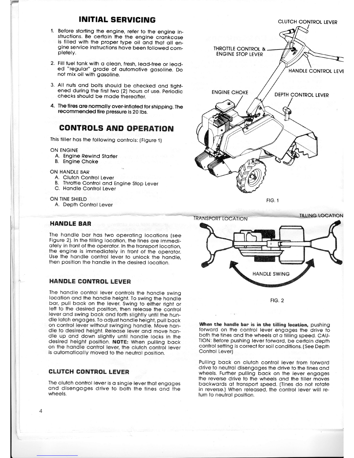
When
thehandle
barisin
tnansport
location,
fheclufch
controllever
will only operofe by pulling
the lever
bock.This
engoges
the driveto the wheels
ond the
tiller movesforword of tronsporl
speed. When re-
leosed,
fhecontrolleverrefurns
to neulrol.
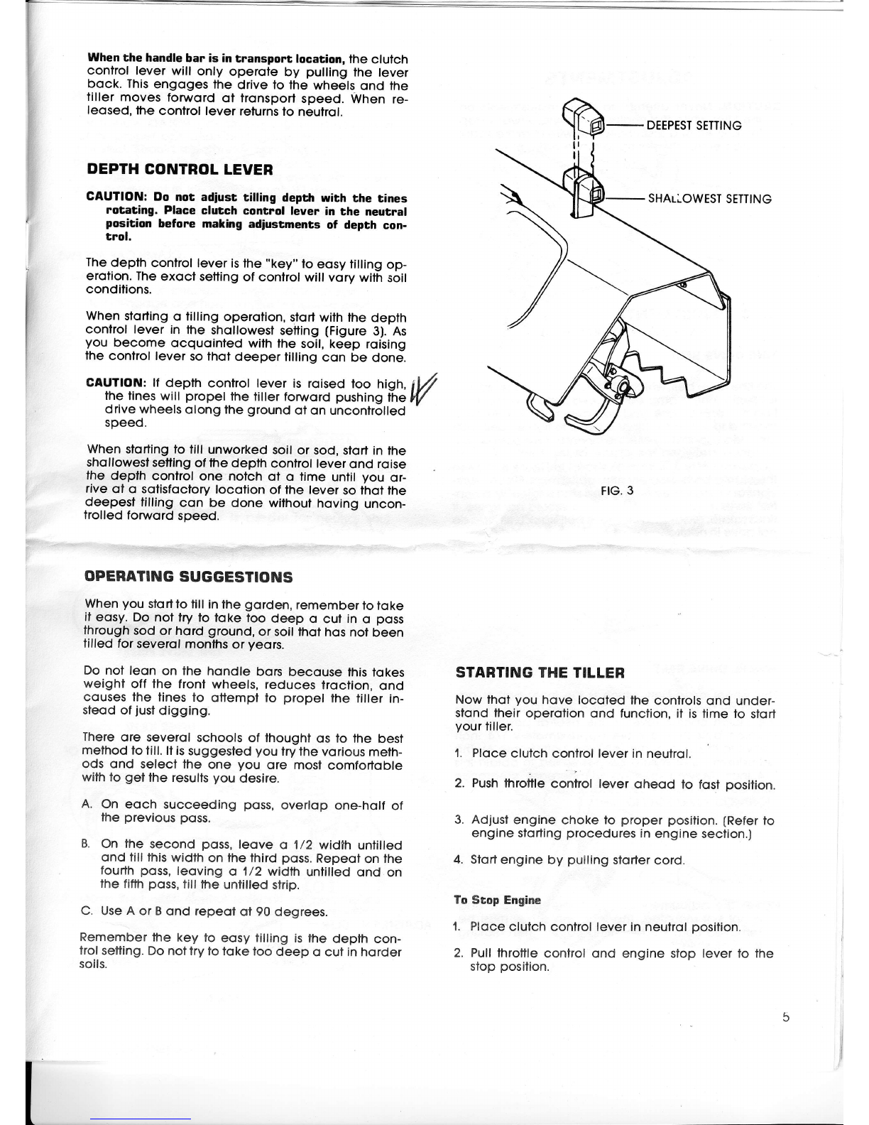
DEPTH
CONTROL
LEVER
GAUTION:
Do nor adiust rilling depthwfth rhe tines
rotatang.
Place
clutch control leyerin the neutral
position before makhrg
adiustmentsof depth con-
trol.
The
depth conirollever
isthe"key"to eosytillingop-
erotion.The
exoct setting
of controlwill vorywilh soil
condilions.
When
storling
o tilling operotion,
stortwiththe depth
confrol lever in lhe shollowesf
setting
(Figure
3).As
you become ocquointedwith
thesoil,
keep roising
thecontrollever
sothofdeepertilling
con be done.
CAUTfON:ff depth control lever is roised loo high,
iV
thelineswill propel the tillerfonruord
pushing
the
lV
drivewheels
olong
the
ground
ofon uncontrolled
speed.
When
sfortingto till unworked
soilor sod,sfortinthe
shqllowest
setting
offhedepth confrollever
ond roise
lhe depth control one notch ol o time unlil you or-
riveol o sofistocfory
locolion of the leversothotthe
deepest
tilling
con be done withouthovinguncon-
frolledfonvordspeed.
OPEBATING SUGGESTIONS
When
you
slortfotill
inthe
gorden,
remember
to
toke
it eosy.Do nol lry to loke too deep o cul in o poss
through
sodor hord ground,
or soilthothosnolbeen
tilled forseverol
monfhs
or yeors.
Donol leon on the hondle borsbecouse
fhistokes
weight off the front
wheels,reducestroction,
ond
cousesthe tines
to ottempl to propel the filler in-
steodofjust
digging.
There
ore severolschoolsof thoughtos to the best
method
totill.ltis
suggested
youlrythevorious
meth-
ods ond selectthe one you ore most
comfortoble
withlo getlhe resulfs
you desire.
A. On eoch succeeding poss,
overlop one-holf
of
theprevious
poss.
B. On the second poss,
leove o 1/2 width untilled
ond tilllhis
width
onlhethird
poss.
Repeot
onihe
fourth
poss,
leovingo 1/2 widthuntilledond on
thefiflh
poss,
tilltheuntilled
strip.
C. Use
A or B
ond repeoi ot 90degrees.
Remember
the key to eosytillingisthe depth con-
trol
setting.Do
nottrylotoke
loodeep o cutinhorder
soils.
FIG.
3
STARTING THE TILLER
Nowthotyouhove locotedthecontrolsond under-
sfondlheiroperotion
ond function,il is
timeto stort
your
tiller.
1. Ploce
clutch
confrolleverinneulrol.
2. Push
throttle
control lever oheod to fosl position.
3. Adjust
enginechokelo properposilion.
(Refer
to
engineslorting
procedures
inengineseclion.)
4. Slort
engineby pulling
slorler
cord.
ToStopEngine
1. Ploce
clutch
control
lever
inneutrol
position.
2. Pull
fhrottle
controlond engine slop lever
to the
stopposilion.
SHAULOWEST
SETTING