Moog Song Producer User manual
TECHNICAL
SERVICE INFORMATION
for
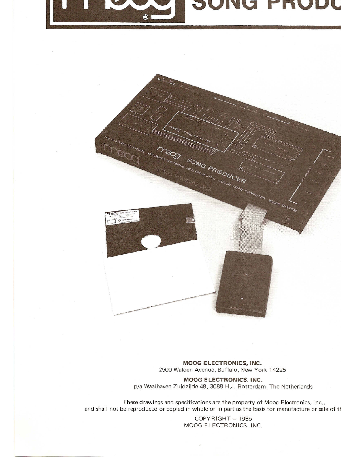
SONG PRODUCER
MOOG
ELECTRONICS. INC.
2500 Walden Avenue. Buffalo.New York 14225
MOOG
ELECTRONICS. INC.
pia Waalhaven Zuidzijde 48,3088 H.J. Rotterdam, The Netherlands
These drawings and specifications are the property ofMoog Electronics. Inc.•
and shallnot bereproduced or copiedinwholeorin partas thebasis for manufacture or sale of theitems.
COPYRIGHT-1985
MOOG ELECTRONICS. INC.
www.bleeps-and-peeps.com

ELECTRICAL SPECIFICATIONS
Operati.g TemperatureRange
Max'Power Consurtption
15 degrees C to40 degrees C
320 milliartps
Triggeri:9
Inn
t
_lIDedance
Input Threshold Voltage
Positive edge
lOOK shunted by .Oluf
+1 volt
TTL cortpatible
100 microseconds
1 Hertz to 500 Hertz
Mini.::: se Width
Clod<Rate
outp
t
D::-
':ve
Puse
~;i
'th
Clock Rate
LSTTL cortpatible
665 microseconds nominal
1Hertz to 300 Hertz
Logic
Inp ~
Ir:;>eeance
I ut esr.old oltage
Logic
OUtput Drive
Active Low
=
Disabled
lOOKshunted by .Oluf
1volt minimum'
TTL compatible
Active Low
=
Disabled
LSTTL cortpatible
Logic
Output rive
Puse"dd-=."
0
tp
ts
••.•.he se_ected
ActiveHigh
=
Trigger
LSTTL cortpatible
200 millisecondsnominal.
Software selectable for latched
or pulsed outputs.
MEMORY MAP
;,
RESS
HEX
=:c
MAL
READ/WRITEFUNCTION
WRITEU17
IlW
Il
CONTROLREGISTER
READUl7
IIW
ll
STATUS DATA REGISTER
WRITE U17
"WI
TRANSMIT DATA REGISTER
READ U17 "WI RECEIVE DATA REGISTER
'f."RITEU18"XII CR
READ U18 "XII SDR
WRITE U18 XTDR
READU18
IIX"
RDR
WRITEU19
"yll
CR
READ U19
"yl1
SDR
w"RITEU19
"yll
TDR
~D U19
llyn
RDR
i'l'TITE U20
"Zll
CR
READ U20
IIZI1
SDR
I'.XI
E U20
"ZI1
TDR
REA U20
HZ
RDR
WRITEDRUM TRIGGER lATCH
WRI EDRUM TRIGGER lATCH
'f.~':'ECONTROLlATCH
'3L E
CONTROL lATCH
~DFOOTSWITCHINPUS
Ri'7I.D
FOOTSWITCH INPUTS
www.bleeps-and-peeps.com
SONGPRODUCER
TEST
ADJUSTMENT ITROUBLESHOOTING
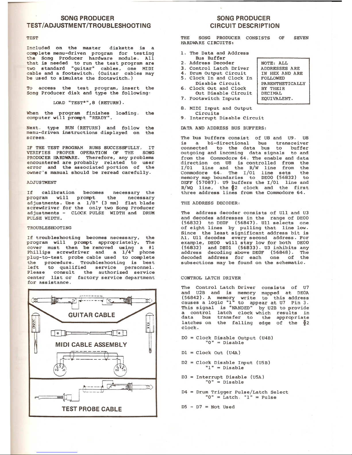
Included on the master diskette is a
complete menu-driven program for testing
the Song Producer hardware module.All
that is needed to run the test program are
~wo standard "guitar" cables, one MIDI
cable and a footswitch.(Guitar cables may
be used to simulate the footswitch.)
To access the test program, insert the
SOng Producer disk and type the following,
When the program finishes loading.the
computer will proMPt "READY".
Next.type RUN (RETURN) and follow the
enu-driven instructions displayed on the
screen.
IF THE TEST PROGRAM RUNS SUCCESSFULLY.IT
VERIFIES PROPER OPERATION OF THE SONG
PRODUCER HARDWARE. Therefore,any problems
encountered are probably related to user
error and the associated portion of the
owner's manual should be reread carefully.
If calibration becomes necessary the
program will prompt the necessary
adjustments. Use a 1/8" (3 mm) flat blade
screwdriver for the only two Song Producer
adjustments - CLOCK PULSE WIDTH and DRUM
PULSE WI DTH •
If troubleshooting becomes necessary, the
program will proMPt appropriately.The
cover must then be removed using a #1
Phillips screwdriver and a 1/4" phone
plug-to-test probe cable used to complete
the procedure. Troubleshooting is best
left to qualified service personnel.
Please consult the authorized service
center list or factory service department
for assistance.
lif-G~=-::-::
1L
it )
0J ~
':----C~==n"0
I '-"
.:..J
.-~-~~
TEST PROBE CABLE
SONG PRODUCER
CIRCUIT DESCRIPTION
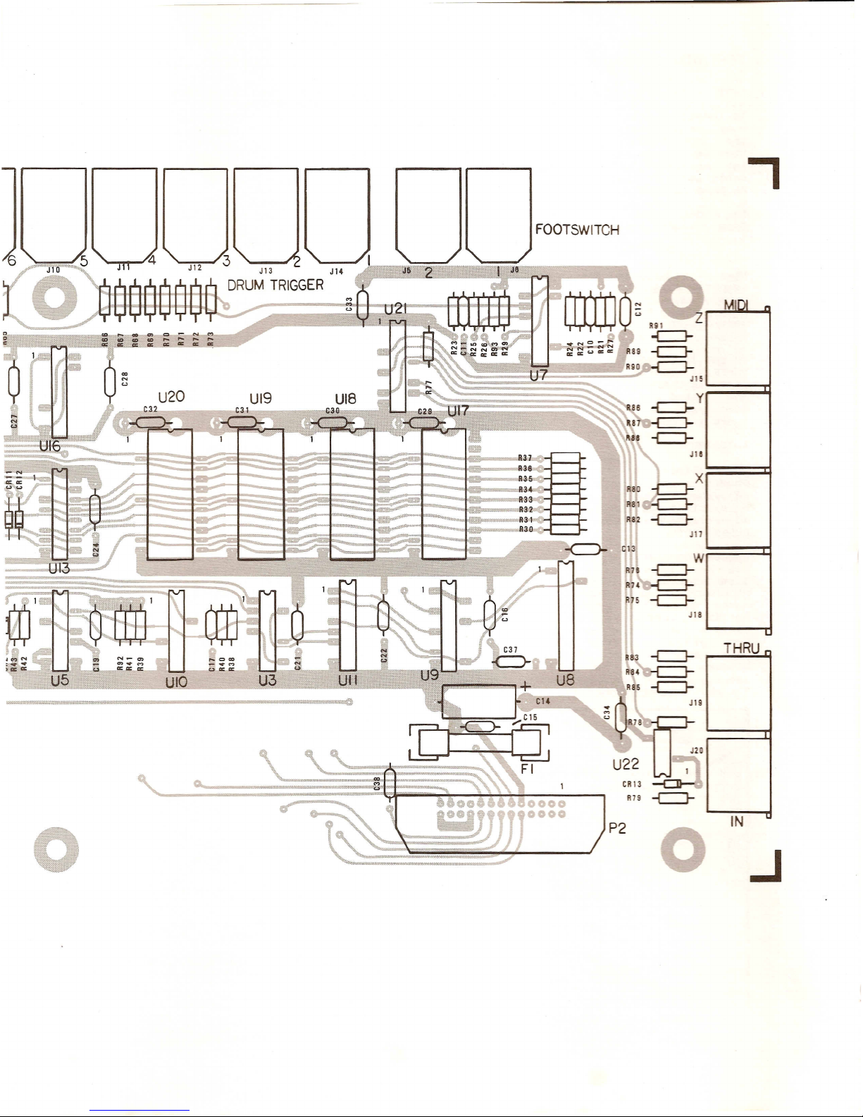
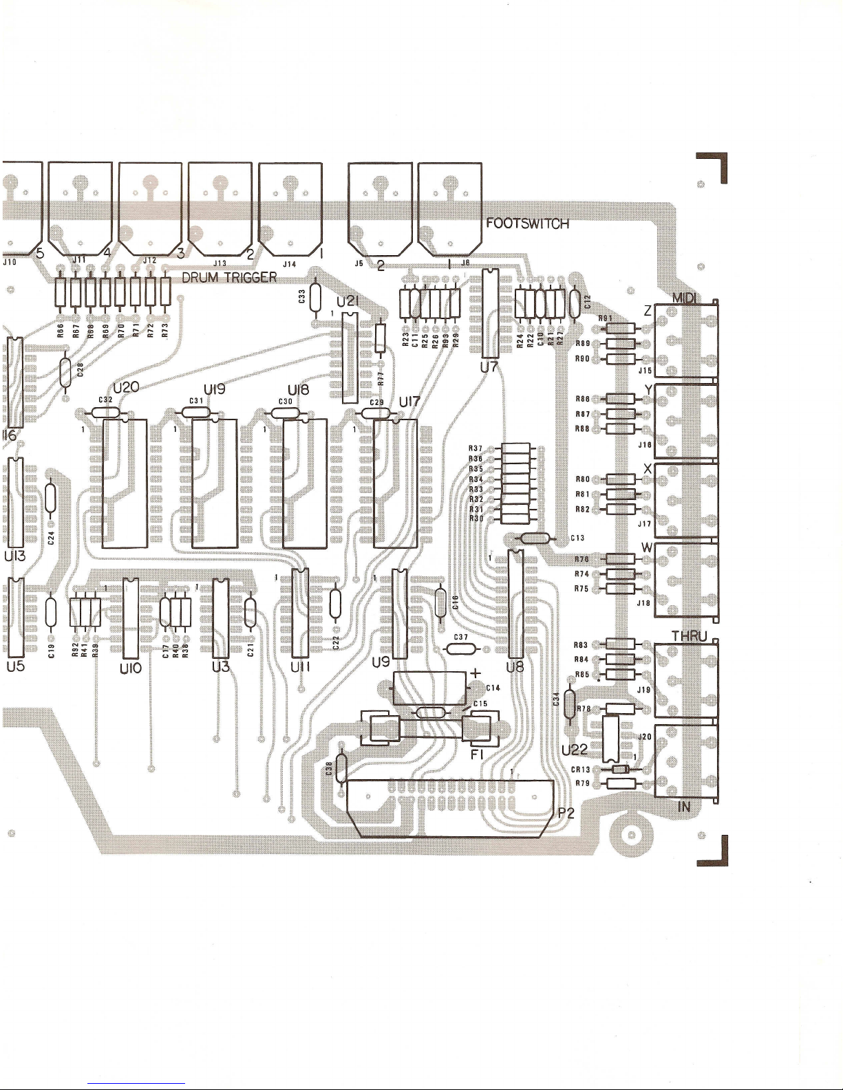
THE SONG PRODUCER CONSISTS
HARDWARE CIRCUITS:
1. The Data and Address
Bus Buffer
2.Address Decoder
3.Control Latch Driver
4.Drum Output Circuit
5. Clock In and Clock In
Disable Circuit
6. Clock Out and Clock
OUt Disable Circuit
7. Footswitch Inputs
NOTE:ALL
ADDRESSES ARE
IN HEX AND ARE
FOLLOWED
PARENTHETICALLY
BYTHEIR
DECIMAL
EQUIVALENT.
8.MIDI Input and Output
Circuits
9.Interrupt Disable Circuit
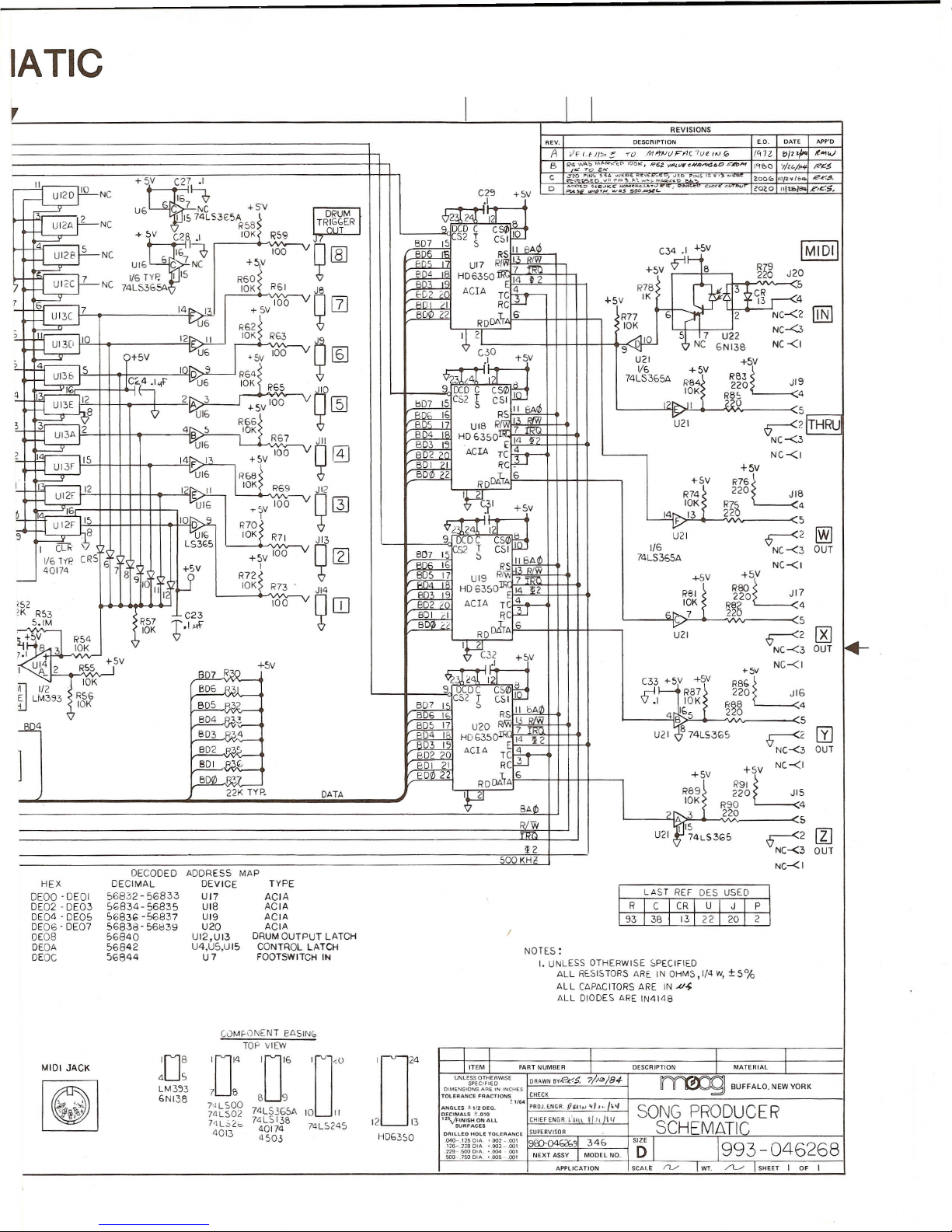
The bus buffers consist of U8 and U9. U8
is a bi-directional bus transceiver
connected to the data bus to buffer
outgoing and incoming data signals to and
from the Commodore 64. The enable and data
direction on U8 is controlled from the
1/01 line and the R/W line from the
Commodore 64. The 1/01 line sets the
memory map boundaries to DEOO (56832) to
DEFF (57087). U9 buffers the 1/01 line and
R/WQ line, the ~2 clock and the first
three address lines from the Commodore 64.
The address decoder consists of UII and U3
and decodes addresses in the range of DEOO
(56832) to DEOF (56847). UII selects one
of eight lines by pulling that line low.
Since the least significant address bit is
AI,UII decodeseverysecond address.For
example, DEOO will stay low for both DEOO
(56832) and DEOI(56833).U3 inhibits any
address decoding above DEOF (56848).The
decoded address for each one of the
subsections may be found on the schematic.
The Control Latch Driver consists of U7
and U2B and is memory mapped atDEOA
(56842). A memorywrite to this address
causes a logic "1"to appear at U7 Pin 3.
This signal is "NANDED" by U2B to provide
a control latch clock which results in
data bus transfer to the appropriate
latches on the falling edge of the ~2
clock.
DO
=
Clock Disable Output (U4B)
"0"
=
Dis able
Clock Disable Input (USB)
"1"
=
Disable
Interrupt Disable (USA)
"0"
=
Disable
Drum Trigger Pulse/Latch Select
"0"
=
Latch."1"
=
Pulse
www.bleeps-and-peeps.com
The drum output circuit consists of
latches U12 and U13,buffers U6 and U16.
pulse timerU14A and R50 and drum mode
latches U15B. The drum output latches can
operate in either a pulse mode or a latch
mode depending on the status of flip flop
U15B. In the latch mode.the output of
U15B is"0", disabling reset circuit U14B.
Data from the buffered data bus is latched
by U13 and U12 DO
=
DRUM TRIGGER 1. D7
=
DRUMTRIGGER 8.
The outputs from U13 and U12 are buffered
by U6 and U16 and sent to the Drum Trigger
outputs 1 through 8.When Pin 13 of UlsB
is high. the drum output operates ina
pulse mode. Whenever a "1" is written to
any output of U13 or U12, diodes CRS
through CR12 couplethat "1"to the input
of U14A. U14A charges C26 through RSO.
When the voltage on C26 equals 2.5 volts,
the output of U14B goes negative resetting
latches U12 and U13 backto zero.C26 and
R50.a drum pulse widthtrim, sets the
time constant and therebyadjusts the
pulse width.
The CLOCK IN(CI) and CLOCK IN DISABLE
(CID) circuits consist of U1,U3A.U2A,
UIO and USB. The CIand CID circuits allow
external instruments,such as drum
machines.to be used as a time base for
the Song Producer.When enabled, clock
pulses on CI generate a non-maskable
interrupt that is fed back to the
Commodore 64andused as a timing signal.
The CID..in conjunction with latch USB.
can be used toinhibit the actionof CI.
Either a "1" on USB or a "0" on CID will
inhibit U2A from passing the clock signal
to UIOD,therebydisabling it. If U2A
generates aninterrupt,the signal is
inverted byUIOD and again byU10C and
sentto the NMI line. Since it is
imperativethat non-maskable interrupts do
notoccur untilthe software sets the
Commodore up to receive them, the A
sectionof US is used to inhibit the
interruptsupon power up.This is
described fullyin theINTERRUPT DISABLE
section.
U4 provides both a CLOCK OUT (CO) and
CLOCKOUT DISABLE (COD) fordriving
external drum machines. Whenever a "1" is
written toBDI of U4A,U4A charges C9
throughR16 andR17.Whenthevoltage on
C9 exceeds thethreshold voltage on the
reset input, U4Aresets to"0" producing a
pulse. R16.R17 and C9 set the pulse width
to 665 microseconds.This is buffered by
U6B andfed toCO. TheCOD is latched by
U4B from BDO.
U7 is a tri-statebuffer used
Footswitch IN1 and 2tothe
Whenever memorylocationDEOC
read.thedata on Footswitch IN
transferred to thedatabuson
6. "0"
=
switch depressed. All
bits areunusedandset
resistors R30throughR37.
to feed
data bus.
(56844)is
1and 2 is
bits 7 and
other data
to
"1"by
To receive information. the serial data
stream is fed to MIDI IN through J20.It
is optically isolated by U22andfed
through buffer U21D to the receive data
input onU17. Whenthe receivedata buffer
receives all8 data bits. an interrupt
request is generated which is fedto the
computer through UIO and a "1" isset in
bit 7 of it's own status register.The
Commodore 64 reads the status register of
each ACIA and when it finds a "1"inbit 7
of th~ status data register, it thenreads
the receive data. Then it is ready to
receive the next serial data transmission.
The receive data stream is also fed to U21
and out the MIDI THROUGH jackto drive
other MIDI based instruments.
Since U17 through U20 all transmit in the
same fashion.we'll only lookat U17.
Whenever the computer wants to send a MIDI
command.it first writes into the transmit
data register of U17.When the data word
is latched. U17adds 1 start bit,then
feeds the data out in a serial stream to
output "W".At the end of the 8 data bits.
it adds one stop bit.When the word is
successfuly transmitted, U17 generates an
interrupt.telling the microprocessor that
it is ready to receive the next word for
transmission.U18, U19 and U20 operate in
exactly the same matter as U17.
It isimperative that no interrupts,
either interrupt requests or non-maskable
interrupts are generated by the Song
Producer before the software has
programmed the Commodore 64to handle
them.Therefore,USA isconfigured to
disable both the NMIvia UIOC and IRQ via
UIOB from the Song Producer uponpower up.
When power issupplied to the Song
Producer,Cl8 holds the reset pin of USA
high forapproximately 1 second. This
causes the "Q" output to go low, disabling
UIOwhich disables both interrupt lines.
To enable both. a "1"is written to USA
which enables UIOB and C. Therefore,the
clock input can then generate a
NON-MASKABLE INTERRUPT (NMI) or the ACIA's
can generate an INTERRUPT REQUEST (IRQ).
MIDI stands for Musical Instrument Digital
Interface. MIDI is a digital serial
communicaion channel (similar to RS232)
that allows similarly equipped instruments
to communicate with eachotherat the
lowest levelthey both understand. In the
case of the Song Producer,MIDI allows the
Commodore 64to communicate and control
synthesizers and drummachines.It
communicates with 10bit words consisting
of one startbit, 8 data bits and 1stop
bit at a 31.25 kHz bit rate. To reduce
ground loops, theMIDIinput isoptically
isolated.
TheMIDI serial data stream isboth
transmitted andreceived by asynchronous
communicationinterface adaptors (ACIA)
U17through U20.The ACIA's are
programmable devices whichcan select
different datarates,word sizes and other
parameters.Thesystemclock 02 is divided
byU15A to 500 kHz. Each of theACIA's is
programmedto divide this clock by 16to
generate the 31.25 kHz timing signalsus~d
for MIDI transmission or reception.
www.bleeps-and-peeps.com
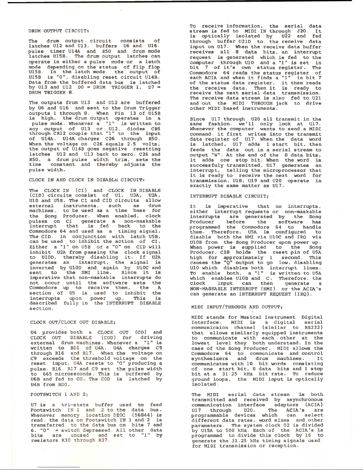
n
ASSEMBLY
996-046270 -001
e--~~ __ ~:
ill)
TOP VIEW
www.bleeps-and-peeps.com
,
KS I
-c:J-
-CJ-
~
J15
-c:J-
JIS
nl
~=----:
R38
X
35
3R8
-e=J-
33 R8 ~
•R32
R82
-c::::J-
c~R31
,.B3
JIJ
••
C13
R1& -c:::J-
R14-c:J
RlO
-c::J-
JIS
~
THRU ,.
R83
R84
i-C::}-
-c:J
@
W',""-:
IN
o
..J
www.bleeps-and-peeps.com

-I
:c
JJ
o
C
Ci)
:c
<
-
m
~
r
C260-
www.bleeps-and-peeps.com
:.J
www.bleeps-and-peeps.com

J
I
ICL?NCKI
NC
NC
NCBD7
BOG
C-64
EXPANSION
PORT
I
I
14
=>------ •..
150>-------7>
1(0)...-----7
170>------.,..
180)...-----.•.
190>------->
200>------.,...
210-------
I
I
I
I
70>------~
50>-------.".
EO>------..."
yO>------..."
X0>------ ...•.
wO>------~
V
0>-------'
uO>------~:
TO-----~,
50>------~.
RO•...
------>
I
I
00>------
.I
I
40>-------;>;
I
I
L
DRUM
TRIGGER
LATCHBD:
+SV
R20
22K
GU2 5
1/4
74LsjlID
S
CONTROL
LATCH
CLOCK
+yV
R'l8
10K
R28
~IK
CI8
IO/50V
±20'lo
C-G4EXPANSION PORT
I~::~:~::~~~~~~~~:::~~~
I
~'•.•"~'1~••·',•.,'_~
'''.'-'<:''~
www.bleeps-and-peeps.com
IATIC
r
III
REVISIONS
REV. DESCRIPTIONE.O.DATE APP'O
A
VF ('fll<;;>.~
'0
Ml'fNvFI'1(7U(./1JGo
(G72
~/'+-
~"'lJ
B
1?4W"::' ""
RI<i:t">
WOI<",
I@I >Z
Vi4tc),eN.Q~< IO~,n,,.,
\"H~)O
'7/,."""
P?K$
~ 7'0ZJ<
.~~ C
J_~~a~""ns ..•~
,,,";'~f.~\~:.•...,.;..•.•
~~:,oPII·.lS
Il."" ""
200(0
1OP.'1/~
R,r., J.
II
D
;....oo:.D
,:,~~~I< .'£,::r:;t:;:.~c...
'<"
t;;UX ""
202.0
Illt.&/~
R,c5.
~NCC25 +}v
U6C7 NC +SV.1
I.
DRUM
&)~
2'11:",21
fuf
J
UI2A 2 NCI IS 74LS3E:5A ~ TRA~I~ER1<589.DCDCCSI/J10
.•sv08 I 10K< RS9
Y
'1'
.'..L
BD7 ISCS2 ~ C"I
~dJ
IMIDII
J
UI28 5NC IE.~ 100
v
9
[ill
~ RSII RA04 'jI4:
~UI66 C 7 NC +~v
Ens
UI7
RJ .~"~
+5V
.r
8~~
1/6TYP.I15 R6~~
~gi
HD6350 E 14~2J20
:J
UI2C7NC 74LS365A10K R61J8Hi2
0
ACTATCrr-R78
C¥f*1~
S
;:=::r~
vg
rn
+5VIK 4
7100 I'In,.IRC 3
-
~
14",. I+5VBUID;,RDDl\rGE.
?T
2NC-<2
mJ
t.1J6 R77
R6~~ 10KNC-<3
~~OI~
10KR63
~[§J
~21AIO ~.17U22 NC-<I
9'q NC 6NI38
~
?+5VU6
R:,tf 100
00 +lV
?...
;\
U21+5V
UI3S 5100¢'23I,,4l
"21
fd
1/6 +5V
[C<'4.1'"u6 10K R6574LS365A RBi' ~~6L9
:..
~'<;
"I
2"" 3
vg~
9IXD C CSal I 10K RBS 4
~;8
-I-5V100bD7 15C,,2 ~ CSI121>-..11
2?~
5
9
VUl6 II
BArf
R6~1
BD5 16~~I., RfW~I
r~~
i.
~24B510K BD"IUIB
Rffl'
7
rRQ
R67JIIBD418 HD 635014
i"?
NC-<3
.....:::=:sr-
UI6
vQ@]
BD315·
<
,
~1514FI'+5V 100BD220 ACIATC:i:t-" NC-<I
"-
UI3FBDI II?C. +5V
~UI6 R6~~BDal 22 RDDlrA6
R~r
R76~
L..
~12I~
10KR69JI2220 JIB
uI2FI
..-'-t
V100-Y~ ~ P~I
~,
UI6
+1.
V10K"754
6
lOr;,...914~13220
:::r
U 12F I">R79~ ¢'2~24112T~
'G;,
5
9'
L8iiJI6 10K R71JI3
r
2~
~.
);
LS3G5 9 DCDCCS0 I
+1V100
v~
[Z]
S071552 SCSI_1/6NC-<3 OUT
1161Y> CR5G7
t~
BD6 16I?S IIbArIJ74LS365ANC-<I
40174 891
:r
R7~~BD5 17 UI9
"IV;~~
R~5G
-
+r
010KR73JI4
~g;
19HD 6350 E 14 12
Ii12
100
9
ITJ
RBI220JI7
?52 BD2
1n
ACIA TC:It-- 10KR88 4
'KR53C23 SOl
;r
RC6C722
S.IM-R57
~.I"+
BOO
d
RDDlrA6
5
10K
r
2
[Kj
~
"54U21
.-
~C
7.1
+
310KC32 NC-<3 OUT
IUh
4
12R55 -I-15V
BD7R30
+5v
11.
1
+1
V
+-5VNC-<I
~ I~
10K
¢
,,j
<41 '1';>1~
C33
+5V
~r
R86
U
R56 BD6 R:'>I 9OCDCCSal?
~-H
R87 220JIG
~LM39310KBD5 R32 SD7ISC52 ~ CSI.110K R~8 4
BD4R;,2BOG If; RS II 6Adl 4r.IG"2 0
4BD5 17u20
~;=~ ~~~
I k
S
SD~ ReA BD4 IHD6350 E 14~2U21
#
74LS3G5
r
2
I1J
BD2tjD315
]
R3"BD2..29ACIA TC±:t--' NC-<3 OUT
SOlpj.(, SOl21RC3+5VNC-<I
BDQ).R07EDal 2 RDDlrA 6
+~r
R91
U
22K TYp.DATA
P
R89 220 JI5
SAUl10K R904
?1f>--3
220
R/w
5
I 15
r
2
1I]
U2174LS3<;5
~2 NC-<3 OUT
SOOKH2NC-<I
DECODED ADDRESS MAP
HEXDECIMAL DEVICE TYPE
I I
DEOO ·DEOI56832-56833 UI7 ACIALASTREF DES USED
DE02·DE0356834-56835UI8ACIA
I
R
I
C
I
CR
I
U[J
I
P
I
DE04 . DE05 5683'; -56837UI9ACIA
I
93
I
38
I
13
1
2 2
I
20
I
2
I
DE06' DE0756838'56839U20 ACIA
,
OED8%840U12,U13DRUMOUTPUT LATCH
DEOA56842U4,U5,UI5CONTROL LATCHNOTE5 :
DEOC5<;844 U7FOOTSWITCH INI. UNLESS OTHERWISESPECIFIED
ALLR~SISTORS AREINOHMS,I/4W,±5%
ALL CAPACITORSARE IN.u~
ALL DIODES ARE IN414B
C0M~\)NENTEASIN(,
TOPVIEW
I I
108
U
U
DC'0"
I
II
MIDI JACK
liTEM
I
PARTNUMBER
I
DESCRIPTION
I
MATERIAL
I
4S
UNLESS OTHERWiSE
DRAWNBV,e",5.
7/''''/84-
~BUFFALO,
NEW
YORK
SPECIFIED
g
LM3537BB 9
DIMENSIONSARE IN INCHES
CHECK
6NI38
TOLERANCE FRACTIONS
7'JLSOO
.H64
PAOH.NGR.(I'lJ,\I1,<Ij •./l'4
A.NGLES±1120EG.
SONG PRODUCER
,~~~.
74LS0274LS3651110II
DECIMALSt.Ol0
CHIEFENGR.l·~1 l ~, II
h
II
HL;o,2b 7~~~~JB 74LS2451213
125-.,kINISH ON ALL
SCHEMATIr:
SURFACES
40,,, 4503HD6350 DRILLED HOLE TOLERANCE
SUPERVISOR
.040-.115 DIll,'002-,001
920-04b2b31 34& SIZE
1993-046268
126-2280IA '.003-,001
D
229-5000IA,
-.004-
001
NEXT ASSYIMODEL NO.
500 .1SODIA '.005-.001
APPLICATION
SCALE
rv
I
WT.
/l.../
SHEET
I
OF I
www.bleeps-and-peeps.com
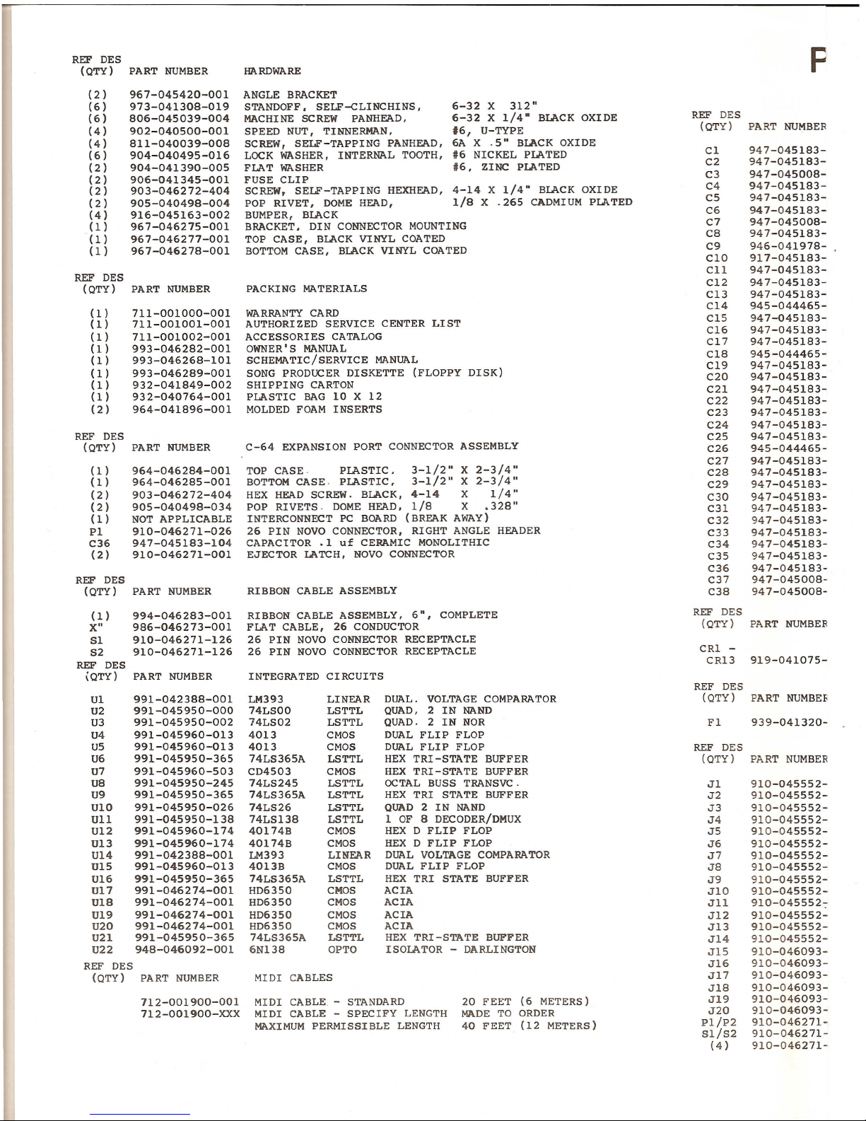
REF DES
(QTY) PART NUMBER
(2 )
(6)
(6)
(4)
(4)
(6)
(2 )
(2)
(2 )
(2 )
(4 )
(1)
(1)
(1)
REF DES
(QTY)
(1)
(1)
(1)
(1)
(1)
(1)
(1)
(1)
(2)
REF DES
(QTY)
(1)
(1)
(2 )
(2 )
(1)
PI
C36
(2)
REF DES
(QTY)
(1)
X"
51
S2
REF DES
(QTY)
967-045420-001
973-041308-019
806-045039-004
902-040500-001
811-040039-008
904-040495-016
904-041390-005
906-041345-001
903-046272-404
905-040498-004
916-045163-002
967-046275-001
967-046277-001
967-046278-001
711-001000-001
711-001001-001
711-001002-001
993-046282-001
993-046268-101
993-046289-001
932-041849-002
932-040764-001
964-041896-001
964-046284-001
964-046285-001
903-046272-404
905-040498-034
NOT APPLICABLE
910-046271-026
947-045183-104
910-046271-001
994-046283-001
986-046273-001
910-046271-126
910-046271-126
Ul 991-042388-001
U2 991-045950-000
U3 991-045950-002
U4991-045960-013
U5 991-045960-013
U6 991-045950-365
U7 991-045960-503
U8 991-045950-245
U9 991-045950-365
U10991-045950-026
Ull991-045950-138
U12991-045960-174
U13 991-045960-174
U14991-042388-001
U15 991-045960-013
U16 991-045950-365
U17 991-046274-001
U18991-046274-001
U19 991-046274-001
U20 991-046274-001
U21 991-045950-365
U22 948-046092-001
REF DES
(QTY) PART NUMBER
712-001900-001
7l2-001900-XXX
ANGLE BRACKET
STANDOFF.SELF-CLINCHINS,
MACHINE SCREW PANHEAD,
SPEED NUT, TINNERMAN,
SCREW, SELF-TAPPING PANHEAD,
LOCK WASHER, INTERNAL TOOTH,
FLAT WASHER
FUSE CLIP
SCREW, SELF-TAPPING HEXHEAD, 4-14 X1/4" BLACK OXIDE
POP RIVET.DOME HEAD,1/8 X .265 CADMIUM PLATED
BUMPER, BLACK
BRACKET.DINCONNECTOR MOUNTING
TOP CASE,BLACK VINYL COATED
BOTTOM CASE.BLACK VINYL COATED
6-32 X 312"
6-32 X 1/4-BLACK OXIDE
16, U-TYPE
6A X .5"BLACK OXIDE
#6NICKEL PLATED
#6, ZINC PLATED
WARRANTY CARD
AUTHORIZED SERVICE CENTER LIST
ACCESSORIES CATALOG
OWNER'SMANUAL
SCHEMATIC/SERVICE MANUAL
SONG PRODUCER DISKETTE (FLOPPY DISK)
SHIPPING CARTON
PLASTIC BAG 10 X 12
MOLDED FOAM INSERTS
TOP CASE PLASTIC, 3-1/2" X 2-3/4"
BOTTOMCASE.PLASTIC, 3-1/2" X 2-3/4"
HEX HEAD SCREW. BLACK, 4-14 X 1/4"
POP RIVETS·DOME HEAD.1/8 X.328"
INTERCONNECT PC BOARD (BREAK AWAY)
26 PIN NOVO CONNECTOR,RIGHT ANGLE HEADER
CAPACITOR .1
uf
CERAMIC MONOLITHIC
EJECTOR LATCH,NOVO CONNECTOR
RIBBONCABLE ASSEMBLY,6", COMPLETE
FLAT CABLE, 26 CONDUCTOR
26 PIN NOVO CONNECTOR RECEPTACLE
26 PIN NOVO CONNECTOR RECEPTACLE
LM393
74LSOO
74LS02
4013
4013
74LS365A
CD4503
74LS245
74LS365A
74LS26
74LS138
40174B
40174B
LM393
4013B
74LS365A
HD6350
HD6350
HD6350
HD6350
74LS365A
6N138
LINEAR
LSTTL
LSTTL
CMOS
CMOS
LSTTL
CMOS
LSTTL
LSTTL
LSTTL
LSTTL
CMOS
CMOS
LINEAR
CMOS
LSTTL
CMOS
CMOS
CMOS
CMOS
LSTTL
OPTO
DUAL.VOLTAGE COMPARATOR
QUAD, 2 IN NAND
QUAD.2 IN NOR
DUAL FLI P FLOP
DUAL FLIP FLOP
HEXTRI-STATE BUFFER
HEXTRI-STATE BUFFER
OCTAL BUSS TRANSVC.
HEX TRI STATE BUFFER
QUAD2IN NAND
1OF 8DECODER/DMUX
HEXD FLIP FLOP
HEXD FLIP FLOP
DUAL VOLTAGE COMPARATOR
DUAL FLIP FLOP
HEXTRISTATE BUFFER
ACIA
ACIA
ACIA
ACIA
HEXTRI-STATEBUFFER
ISOLATOR - DARLINGTON
MIDI CABLE.-STANDARD
MIDI CABLE - SPECIFYLENGTH
MAXIMUMPERMISSIBLE LENGTH
20 FEET(6 METERS)
MADE TOORDER
40 FEET(12 METERS)
REF DES
(QTY)
Cl
C2
C3
C4
C5
C6
C7
C8
C9
CI0
C11
C12
C13
C14
C15
C16
C17
C18
C19
C20
C21
C22
C23
C24
C25
C26
C27
C28
C29
C30
C31
C32
C33
C34
C35
C36
C37
C38
REF DES
(QTY)
CRI -
CR13
REF DES
(QTY)
REF DES
(QTY)
Jl
J2
J3
J4
J5
J6
J7
J8
J9
JI0
J11
J12
J13
J14
J15
J16
J17
J18
J19
J20
Pl/P2
Sl/S2
(4)
947-045183-
947-045183-
947-045008-
947-045183-
947-045183-
947-045183-
947-045008-
947-045183-
946-041978-
917-045183-
947-045183-
947-045183-
947-045183-
945-044465-
947-045183-
947-045183-
947-045183-
945-044465-
947-045183-
947-045183-
947-045183-
947-045183-
947-045183-
947-045183-
947-045183-
945-044465-
947-045183-
947-045183-
947-045183-
947-045183-
947-045183-
947-045183-
947-045183-
947-045183-
947-045183-
947-045183-
947-045008-
947-045008-
910-045552-
910-045552-
910-045552-
910-045552-
910-045552-
910-045552-
910-045552-
910-045552-
910-045552-
910-045552-
910-045552-:-
910-045552-
910-045552-
910-045552-
910-046093-
910-046093-
910-046093-
910-046093-
910-046093-
910-046093-
910-046271-
910-046271-
910-046271-
www.bleeps-and-peeps.com

~ARTSLIST REF DES
(QTY) PART NUMBER RESISTORS
Rl 852-312104-001 lOOK 1/41015%CARBON FILM
R2 852-312103-001 10K 1/4W 5%CARBON FILM
R3 852-312393-001 39K 1/41015% CARBONFILM
R4 852-312103-001 10K 1/4W5%CARBON FILM
CAPACITORS R5 852-312105-001 1M 1/41015% CARBONFILM
R6 852-312472-001 4 7K 1/41015%CARBNFILM
103 .01 uf CERAMIC MONOLITHICR7 852-312104-001 lOOK1/41015%CARBON FILM
104 .1 uf CERAHIC MONOLITHICR8 852-312103-001 10K 1/41015% CARBON FILM
102 .001 uf CERAMIC TUBULAR R9 852-312303-001 30K 1/4'<15% CARBON FILM
104 .1 uf CERAMIC MONOLITHIC RlO 852-312513-001 51K 1/41015% CARBONFILM
104 .1uf CERAMIC MONOLITHIC Rll 852-312203-001 20K 1/41015% CARBONFILM
R12 852-312105-001 1M1/41015% C.'.RBaN FILM
104 .1 uf CERAMIC MONOLITHIC Rl3 852-312472-001 4.7K 1/41015%Ck.=N FILM
102 .001 uf CERAMIC TUBULAR R14 852-312101-001 100 OHM 1/41015% CARBON FILM
104 .1 uf CERAMIC MONOLITHIC Rl5 852-312103-001 10K 1/41015%CARBONFILM
393 .039 uf 10% 50VPOLYESTERRl6 852-312103-001 10K1/41015% CARBON FILM
104 .1 uf CERAMIC MONOLITHIC Rl7 925-042526-005 lOOK LINEAR CERMET TRIM
CLOCK PULSE WIOTH
104 .1 uf CERAMIC MONOLITHICR18 852-312101-001 100 OHM1/41015% CARB N FILM
104 .1 uf CERAMIC MONOLITHIC R19 852-312103-001 10K 1/41015% CARBON FILM
104 .1 uf CERAMIC MONOLITHIC R20 852-312223-001 22K 1/41015% CARBONFILM
006 220 uf 6.3V AL ELECTROLITIC R21 852-312103-001 10K1/41015% CARBON FILM
104 .1uf CERAMIC MONOLITHIC R22 852-312103-001 10K 1/41015% CARBONFILM
R23 852-312103-001 10K 1/41015% CARBNFILM
104 .1 uf CERAMIC MONOLITHICR24 852-312103-001 10K1/41015% CARBON FILM
104.1 uf CERAMIC MONOLITHIC R25 852-312103-001 10K 1/41015%CARBON FILM
004 10 uf 50V AL ELECTROLITIC R26 852-312103-001 10K 1/41015% CARBON FILM
104 .1 uf CERAMIC MONOLITHIC R27 852-312103-001 10K 1/41015% CARBON FILM
104 .1 uf CERAMIC MONOLITHIC R28 852-312102-001 lK 1/41015% CARBON FILM
104 .1 uf CERAMIC MONOLITHIC R29 852-312223-001 22K 1/41015% CARBON FILM
R30 852-312223-001 22K 1/41015% CA.RBONFILM
104 1 uf CERAMIC MONOLITHIC R31 852-312223-001 22K1/41015% CARBONFILM
104 .1uf CERAMIC MONOLITHIC R32 852-312223-001 22K1/41015% CARBON FILM
104 .1uf CERAMIC MONOLITHIC R33 852-312223-001 22K1/41015% CARB N FILM
104 .1uf CERAMIC MONOLITHIC R34 852-312223-001 22K 1/41015% CARBONFILM
002 1uf 150V AL ELECTROLITIC R35 852-312223-001 22K1/41015% CARBON FILM
R36 852-312223-001 22K1/4W5% CARBON FILM
104 .1uf CERAMIC MONOLITHIC R37 852-312223-001 22K1/41015% C~.RBON FILM
104 .1uf CERAMIC MONOLITHIC R38 852-312223-001 22K 1/4 ••5% CARBON FILM
104 .1 uf CERAMIC MONOLITHIC R39 852-312223-001 22K 1/41015%CARBON FILM
104 .1uf CERAMIC MONOLITHIC R40 852-312103-001 10K 1/41015% C.".RBON FILM
104.1 uf CERAMIC MONOLITHIC R41 852-312103-001 10K 1/41015% CARB N FILM
104.1uf CERAMIC MONOLITHIC R42 852-312104-001 lOOK1/41015% CARBONFILM
104 .1 uf CERAMIC MONOLITHIC R43 852-312204-001 200K 1/41015% CA;rnoN FILM
R44 852-312223-001 22K1/41015% CA.R3NFILM
104.1 uf CERAMIC MONOLITHIC R45 852-312223-001 22K1/41015%
A..-=tBON FILM
104 .1uf CERAMIC MONOLITHIC R46 852-312103-001 10K1/41015% CARS N FILM
104.1uf CERAMIC MONOLITHIC R47 852-312515-001 5.1M1/41015% CARBON FILM
470 47 pf CERAMIC TUBULAR R48 852-312103-001 10K 1/41015% CARBON FILM
470 47 pf CERAMIC TUBULAR R49 852-312103-001 10K1/41015% C.;;R30NFILM
RSO 925-042526-005 lOOKLIN"...ARCER"IE'l'TRIM
DRUM PULSE "'"IOTH
DIODES RS1 852-312102-001lK1/41015% CARBON FILM
RS2 852-312202-001 2K1/41015% CARBON FILM
R53 852-312515-001 5.1M1/41015% CARBONFILM
R54852-312103-001 10K1/41015% CARBON FILM
DOl IN4148 SIGNAL DIODE R55 852-312103-001 10K 1/41015% CARBON FILM
R56 852-312103-001 10K1/41015% CARBON FILM
R57 852-312103-001 10K 1/41015% CARBONFILM
R58 852-312103-001 10K 1/41015% CARBON FILM
FUSE R59 852-312101-001 100 OHM 1/41015% CARBON FILM
R60 852-312103-001 10K1/41015%CARBON FILM
004 FUSE, FAST BLOW O. SA 250V 1l.61 852-312101-001 100 OHM1/41015%CARBON FILM
R62 852-312103-001 10K 1/41015% CARBONFILM
R63 852-312101-001 100OHM1/41015% CARBON FILM
R64852-312103-001 10K1/41015% CARBONFILM
JACKS AND CONNECTORS USAGE R65 852-312101-001 100OHM 1/41015% CARBON FILM
R66 852-312103-001 10K1/41015% CARBON FILM
002 JACK,PHONE 1/4"2 CONDUCTOR CLOCK IN R67 852-312101-001 100 OHM 1/41015% CARBONFILM
001 JACK,PHONE 1/4" 2 CONDUCTOR CLOCK OUT R68852-312103-00110K1/41015% CARBON FILM
001 JACK, PHONE 1/4" 2 CONDUCTOR CLOCK DISABLE IN R69852-312101-001 100OHM 1/41015% CARBON FILM
R70 852-312103-00110K 1/41015% CARBON FILM
DOl JACK, PHONE 1/4" 2 CONDUCTOR CLOCKDISABLE OUT Rn 852-312101-001 100OHM 1/41015% CARBON FILM
DOlJACK. PHONE 1/4"2 CONDUCTOR FOOTSWITCH IN 2 R72 852-312103-00110K 1/4W 5% CARBON FILM
001 JACK,PHONE1/4" 2 CONDUCTOR FOOTSWITCHIN1R73 852-312101-001100 OHM 1/4W 5% CARBON FILM
DOl JACK,PHONE 1/4" 2 CONDUCTOR DRUMTRIGGER OUT 8 R74852-312103-001 10K 1/41015% CARBON FILM
JOI
JACK. PHONE1/4" 2 CONDUCTOR DRUMTRIGGER OUT 7R75 852-312221-001220 OHM 1/41015% CARBON FILM
R76852-312221-001 220 OHM 1/41015% CARBONFILM
DOl JACK, PHONE1/4" 2 CONDUCTORDRUMTRIGGER OUT 6 R77852-312103-001 10K1/41015% CARBON FILM
JOI
JACK,PHONE1/4" 2 CONDUCTOR DRUMTRIGGEROUT5R78852-312102-001 1K 1/41015% CARBON FILM
JOI JACK, PHONE1/4" 2 CONDUCTOR DRUMTRIGGER OUT4R79 852-312221-001 220 OHM1/41015% CARBON FILM
DOl JACK.PHONE1/4" 2 CONDUCTOR DRUMTRIGGER OUT3R80 852-312221-001 220OHM 1/41015% CARBONFILM
DOlJACK. PHONE1/4" 2 CONDUCTOR DRUMTRIGGER OUT 2 RBI852-312103-001 10K 1/41015% CARBON FILM
DOl JACK,PHONE1/4" 2 CONDUCTORDRUMTRIGGEROUT 1R82 852-312221-001 220OHM 1/41015% CARBON FILM
R83 852-312221-001 220OHM 1/41015% CARBON FILM
J5
5 PIN DIN CONNECTORMIDI Z OUT R84 852-312103-001 10K1/4W 5% CARBONFILM
DOS 5PIN DIN CONNECTORMIDIYOUTR85 852-312221-001 220 OHM 1/41015% CARBON FILM
J 5
5PIN DIN CONNECTOR MIDI X OUTR86852-312221-001 220 OHM1/41015% CARBON FILM
D05 5 PIN DINCONNECTOR MIDI WOUT R87 852-312103-00110K 1/4W 5%CARBON FILM
J5
5 PINDINCONNECTOR MIDI THRUR88 852-312222-001 220 OHM 1/41015%CARBON FILM
R89 852-312103-001 10K1/41015% CARBON FILM
DOS5PINDIN CONNECTOR MIDI IN R90 852-312221-001 220OHM 1/41015% CARBON FILM
026 26 PINHEADER NOVOCONNECTOR RIBBONCABLER91 852-312221-001 220 OHM1/41015% CARBON FILM
12626PINSOCKET NOVOCONNECTOR RIBBONCABLERn 852-312103-001 10K 1/41015% CARBON FILM
001 EJECTOR LATCHNOVOCONNECTOR RIBBON CABLE R93 852-312223-001 22K 1/41015% CARBON FILM
www.bleeps-and-peeps.com
1
HARDWAREDISCLAIMER
(1) Any instrument which has been modified, alteredor uponwhich theserialnumber has been tampered withor altered, orany instrument which has been
damaged through misuse, negligence,accident orimproper operation, failure
0'
elec ricalpower, usewithother products not manufactured or approvedby
Moog, (2) Any instrument usedfor rentalor loan purposes, (3) Normalwear and ear,tonalcaracteristics,thecleaning ofcontrolsorcontacts, calibration,
improvements,circuit updates,damages inshipping,and cracking or otherda - ~es
0
efinish for anyreason, (4) Any instrument which hasbeen pur,
chased froman unauthorized dealer,(5) Anyresultof acts beyond thecon rol
0'
oogincling unauthorized servicing,tampering, or failure to operate in
accordancewith the procedures outlinedinthe Owner'sManual,or(6)For a so' -suc as loading, lightning,tornados, etc.
This warrantyis extended tothe original retailpurchaser onlyandisno ran 'erable
'0
subsequent owners.
Moogshall have no obligation to enhance orupdateanyunitonce manufactured.
Moog reserves theright to use materials regularlyutilized at thetimeof repc',incevent at originalmaterialsareno longer available.Replacement of the
original instrument maybe at Moog's option with afactoryreconditionedmodel
0"
s·
MOOG MAKES NO OTHER EXPRESSEDWARRANTY OFAYKID=- ER.ALL IPLIEDWARRANTIES,INCLUDINGWARRANTIES
OF MERCHANTABILITY,SUITABIL1TYOR FITNESS FOR APARTICUPOSEAEHEREBYDISCLAIMEDFROM THIS WARRANTY,.IN-
CLUDING BUT NOT LIMITED TO ANY INTERRUPTIONOFSERVICE,LSSOF BUSIESS,ATICIPATORYPROFITS OR CONSEQUENTIAL
DAMAGES OR INCIDENTAL DAMAGES RESULTING FROMTHEUSEOPE
COMPUTER MEDIA DISCLAIMER
THISWARRANTY SHALL NOT APPLYIFTHE COMPUTERMEDIA
IZED SERVICE, OR BYOTHER CAUSES UNRELATED TO DEFECTIVE
MOOGMAKES NO WARRANTIES,EITHER EXPRESSEDORIPlcD,
QUALITY, PERFORMANCE, MERCHANTABILITY ORFITESS FO
ENTIRERISK AS TOITS QUALITY ANDPERFORMACEIS
II
I
ITS PURCHASE, THE BUYER(AND NOTTHE CREATOROFTHEPiWG
MIDI DISCLAIMER
MIDISPECIFICATIONS HAVE BEENIMPLEMENTED DI-FEETL 3
IFIC APPLICATIONS,PARTICULARMODESOFOPEATIO AV'=Y'=-
MAYNOTWORK WITH ALLMIDI EQUIPPED PRODUCTS.
YUSICALISTRUMENTMANUFACTURERS.INSOMESPEC-
aE
PRECISELYDEFINED.THEREFORE, THISMOOG PRODUCT
MANUAL DISCLAIMER
EVERYEFFORT HAS BEENMADETO E SURETHAT TrlEAUCC ELYDOCUMETS THEACCOMPANYING MOOG PRODUCT.
HOWEVER,BECAUSE OFONGOINGIMPROVEMETS A 0 UPD TI-OF0PUTERSOFTWAREANDHARDWARE,MOOG CANNOT GUAR-
ANTEETHE ACCURACY OF PRINTEDMATERIALAFTER THED,:I.T'=BLICATIOA0 SHALL NOT ACCEPT RESPONSIBILITYFOR
ERRORS OR OMISSIONS.
SHIPPINGDISCLAIMER
MOOG SHALL NOT BE LIABLE FOR DAMAGEOR LOSS RESUTIG
'F
ACTSOFTHESHIPPER OR HISCONTRACT AFFILIATES. THE
CUSTOMERSHOULD CONTACT THESHIPPERFOR PROPERCLAICEO RESITHE EVENTOF DAMAGEORLOSS RESULTING FROM
SHIPMENT.
I II II I
NO POSTAGE
NECESSARY
IFMAILED
IN
THE
UNITED STATES
MOOG ELECTRONICS INC.
2500 Walden Avenue
BUFFALO, NEW YORK 14225
NOTICE
OWNER ADDRESS CHANGE
www.bleeps-and-peeps.com
Table of contents


