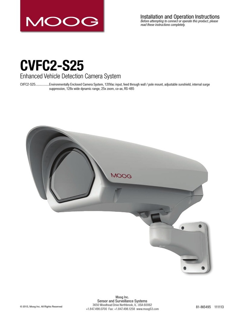
Moog CVFC2-S25 User manual

Moog Inc.
Sensor and Surveillance Systems
3650 Woodhead Drive Northbrook, IL. USA 60062
+1.847.498.0700 Fax: +1.847.498.1258 www.moogS3.com
1/4” 25x High Resolution WDR
Zoom Camera with NTSC
Power Zoom Camera System
Installation and Operation Instructions
Before attempting to connect or operate this product, please
read these instructions completely.
© 2013, Moog Inc. All Rights Reserved 81-IN5494 120613

IMPORTANT SAFEGUARDS SAFETY PRECAUTIONS
UNPACKING
SERVICE
1 Read these instructions.
2 Keep these instructions.
3 Heed all warnings
4 Follow all instructions.
5 Do not use this apparatus near water.
6 Clean only with damp cloth.
7 Do not block any of the ventilation openings. Install in accordance with the
manufacturers instructions.
8 Cable Runs- All cable runs must be within permissible distance.
9 Mounting - This unit must be properly and securely mounted to a supporting
structure capable of sustaining the weight of the unit.
Accordingly:
a. This installation should be made by a qualied service person and should conform
to all local codes.
b. Care should be exercised to select suitable hardware to install the unit, taking into
account both the composition of the mounting surface and the weight of the unit.
10 Do not install near any heat sources such as radiators, heat registers, stoves, or other
apparatus ( including ampliers) that produce heat.
11 Do not defeat the safety purpose of the polarized or grounding-type plug. A
polarized plug has two blades with one wider than the other. A grounding type
plug has two blades and a third grounding prong. The wide blade or the third
prong are provided for your safety. When the provided plug does not t into your
outlet, consult an electrician for replacement of the obsolete outlet.
12 Protect the power cord from being walked on or pinched particularly at plugs,
convenience receptacles, and the point where they exit from the apparatus.
13 Only use attachment/ accessories specied by the manufacturer.
14 Use only with a cart, stand, tripod, bracket, or table specied by the manufacturer,
or sold with the apparatus. When a cart is used, use caution when moving the cart/
apparatus combination to avoid injury from tip-over.
15 Unplug this apparatus during lighting storms or when unused for long periods of time.
16 Refer all servicing to qualied service personnel. Servicing is required when the
apparatus has been damaged in any way, such as power-supply cord or plug is
damaged, liquid has been spilled of objects have fallen into the apparatus, the
apparatus has been exposed to rain or moisture, does not operate normally, or
has been dropped.
Be sure to periodically examine the unit and the supporting structure to make sure that the integrity
of the installation is intact. Failure to comply with the foregoing could result in the unit separating
from the support structure and falling, with resultant damages or injury to anyone or anything struck
by the falling unit.
Unpack carefully. Electronic components can be
damaged if improperly handled or dropped. If an item
appears to have been damaged in shipment, replace
it properly in its carton and notify the shipper.
Be sure to save:
1 The shipping carton and packaging material.
They are the safest material in which to make future
shipments of the equipment.
2 These Installation and Operating Instructions.
If technical support or service is needed, contact us at
the following number:
The lightning ash with an arrowhead symbol,
within an equilateral triangle, is intended to
alert the user to the presence of non-insulated
“dangerous voltage” within the product’s
enclosure that may be of sufcient magnitude
to constitute a risk to persons.
Este símbolo se piensa para alertar al usuario a la presencia
del “voltaje peligroso no-aisIado” dentro del recinto de los
productos que puede ser un riesgo de choque eléctrico.
Ce symbole est prévu pour alerter I’utilisateur à la presence
“de la tension dangereuse” non-isolée dans la clôture de
produits qui peut être un risque de choc électrique.
Dieses Symbol soll den Benutzer zum Vorhandensein der
nicht-lsolier “Gefährdungsspannung” innerhalb der
Produkteinschließung alarmieren die eine Gefahr des
elektrischen Schlages sein kann.
Este símbolo é pretendido alertar o usuário à presença “di
tensão perigosa non-isolada” dentro do cerco dos produtos
que pode ser um risco de choque elétrico.
Questo simbolo è inteso per avvertire I’utente alla presenza
“di tensione pericolosa” non-isolata all’interno della
recinzione dei prodotti che può essere un rischio di scossa
elettrica
.
The exclamation point within an equilateral
triangle is intended to alert the user to
presence of important operating and
maintenance (servicing) instructions in the
literature accompanying the appliance.
Este símbolo del punto del exclamation se piensa para
alertar al usuario a la presencia de instrucciones importantes
en la literatura que acompaña la aplicación.
Ce symbole de point d’exclamation est prévu pour alerter
l’utilisateur à la presence des instructions importantes dans
la littérature accompagnant l’appareil.
Dieses Ausruf Punktsymbol soll den Benutzer zum
Vorhandensein de wichtigen Anweisungen in der Literatur
alarmieren, die das Gerät begleitet.
Este símbolo do ponto do exclamation é pretendido alertar o
usuário à presença de instruções importantes na literatura
que acompanha o dispositivo.
Questo simbolo del punto del exclamaton è inteso per
avvertire l’utente alla presenza delle istruzioni importanti nella
letteratura che accompagna l'apparecchio.
TECHNICAL SUPPORT
AVAILABLE 24 HOURS
1- 800-554 -1124
RISK OF ELECTRIC SHOCK
DO NOT OPEN
CAUTION
CAUTION: TO REDUCE THE RISK OF
ELECTRIC SHOCK, DO NOT REMOVE
COVER ( OR BACK). NO USER- SERVICE-
ABLE PARTS INSIDE. REFER SEVICING
TO QUALIFIED SERVICE PERSONNEL.
MADEIN
BUY AMERICA COMPLIANT • COUNTRY OF ORIGIN U.S.A.
USA
overview
FCC STATEMENT
THIS DEVICE COMPLIES WITH PART 15 OF THE FCCRULES. OPERATION IS SUBJECT TO THE
FOLLOWING TWO CONDITIONS :
1) THIS DEVICE MAY NOT CAUSE HARMFUL INTERFERENCE, AND
2)
THIS DEVICE MUSTACCEPTANY INTERFERENCE RECEIVED INCLUDING INTERFERENCE THATMAY
CAUSE UNDESIRED OPERATION.
Caution
THIS EQUIPMENT HAS BEEN TESTED AND FOUND TO COMPLY WITH THE LIMITS FOR A CLASS A DIGITAL
DEVICE, PURSUANT TO PART 15 OF FCC RULES. THESE LIMITS ARE DESIGNED TO PROVIDE REASONABLE
PROTECTION AGAINST HARMFUL INTERFERENCE WHEN THE EQUIPMENT IS OPERATED IN A COMMER-
CIAL ENVIRONMENT.
THIS EQUIPMENT GENERATES, USES, AND CAN RADIATE RADIO FREQUENCY ENERGY AND, IF NOT
INSTALLED AND USED IN ACCORDANCE WITH THE INSTRUCTION MANUAL, MAY CAUSE HARMFUL IN-
TERFERENCE TO RADIO COMMUNICATIONS. OPERATION OF THIS EQUIPMENT IN A RESIDENTIAL AREA IS
LIKELY TO CAUSE HARMFUL INTERFERENCE IN WHICH CASE THE USER WILL BE REQUIRED TO CORRECT
THE INTERFERENCE AT HIS OWN EXPENSE.
IC COMPLIANCENOTICE
THIS CLASS A DIGITAL APPARATUS MEETS ALL REQUIREMENTS OF THE
CANADIAN INTERFERENCE.-CAUSING EQUIPMENT REGULATIONS OF ICES-003.

FEATURES
With the sta te-of-the-art digital signal processing technology, full digital image
processing and special algorithm of 600-line high resolution implemented.
High Sensitivity: It implements images of high sensitivity using the up-to-date
VPS(Virtual Progressive Scan): This is an advanced technology that reproduces
a sharp progressive image. This is appropriate to high quality recording and file
transfer via the Internet.
High performance surveillance camera, equipped with x25 zoom lens and digital
zoom IC, enabling monitoring up to 400 times
WDR extends the contrastrange as it takes a picture of each of darkand bright areas
before compositing the two, which is useful if you take a picture of windows inside
a building. Namely, it improves the picture quality of the outdoor sceneryas well as
Low Illumination: It uses the digital signal technologies such as low illumination and
Day/Night functions that make your camera identify objects even in the worst envi-
ronment.
XDR (eXtended Dynamic Range): Actively controls the gamma compensation in the
way it operates the ambient luminance contrast in a certain pixel unit to determine
the optimal visibility.
DAY/NIGHT:
This function can make the IRCut filtering function inactive under the illumina-
tion below the normal value.
White B alance to control the brightness to the illumination
Superior Backlight Adjustment:When an object has a bright illumination or sunlight
behind it, this camera automatically improves the shaded object picture quality.
Auto Focus to automatically adjust the focus to the subject movement
Privacy zone to hide a specific area for personal privacy.
ExView-HAD PS CCD.
indoor.

Rear Panel
Input/Output Connector
This connector has input and output ports for RS-485 control signals,
DAY/NIGHT switching, and alarm output signals.

overview
1. ALARM OUT
Alarm out jack for motion detection. (Open Collector, On Gnd)
2. GND
Grounding jack.
Displays the current still image when it r eceives the T rigger signal. (Normal
Open Type)
4.5.6 FOCUS, COM, ZOOM
This port is used for ZOOM/FOCUS, MENU CONTROL, HOME
RETURN, and ONEAF by using an external controller.
Depending on the input condition, 4 modes, A, B, C, and D are
available. (SPECIAL - CTRL TYPE)
(Operation Voltage Range : +3V~+13V, -3V~-13V)
1) When the voltage is supplied to either ZOOM or FOCUS port
Function
*1
Code
Tele(Up)
Wide(Down)
Near(Left) Far(Right)
ZOOM Port FOCUS Port
A -6V +6V -6V +6V
B -6V +6V +6V -6V
C +6V -6V -6V +6V
D+6V -6V +6V -6V
*1: During ME NU OFF, controls ZOOM/FOC US and during ME NU ON,
changes the direction, Up/Down/Left/Right SETUP switch.
2) When the voltage is supplied to both ports
Function
Code
ENTER/AF *2 HOME RETURN *3
ZOOM Port
FOCUS Port
ZOOM Port
FOCUS Port
A -6V -6V +6V +6V
B -6V +6V +6V -6V
C +6V -6V -6V +6V
D+6V +6V -6V -6V
3. TRIGGER IN

* 2 : For short voltage supply during MENU OFF, executes ONEAF and for
more than 2 second
* 3 : For more than 2 second long voltage supply, moves to the PRESET
0(HOME) position.
7. 5V OUT
Power supply jack for RS-485 JIG. Use within typical DC +5V 100mA.
8. DA Y/NIGHT IN
This is a function to receive the external DAY/NIGHT signal from the
sensor(option) and convert the signal into BW.
9. RS-485 DATA-
Jack for connection to RS-485 DATA- signal line.
10. RS-485 DATA+
Jack for connection to RS-485 DATA+ signal line.
SETUP Switch
This switch is used to set the function or pr operty. When this switch is pressed
for at least 2 seconds, theMAIN MENU appears.
(Left/Right)
: By pressing this switch left or right, you can moveleft or right
on the menu or change the displayed value.
(Up/Down) :
By pressing this switch upor down, you can move up or down on
the menu.
: When you pressthis switch in the menu, the selected function is confirmed.
To enter a submenu, press this button.
Video OUT Port
This is connected to the Video Input Port of the monitor and it outputs the
Video signals.
GND
This is a grounding port.
Power Connection Port
This is connectedto the Power cable.
Power Display LED
When the power is normally connected, the red LED lights.

installation & connection
4. Determine the type of power supply and set the POWER SELECTION switch
accordingly. Next, plug the power adapter into a wall outlet.
5 seconds and then disappears.
6. The requir ements for RS485 control is as follows :
- Signaling Speed: 9600 bps
- Data Bit : 8 bits
- Stop Bit : 1 bit
- Parity Bit : none
TYPE 4_25ZOM_WDR_N
PROTOCOL SAMSUNG
0SSERDD A
COMM.TYPE RS485,HALF
BAUDRATE 9600
K OSNE L
SAMSUNG-E
CAMERA VER. v2.00_100501
PROTOCOL SAMSUNG
0SSERDDA
COMM.TYPE RS485,HALF
BAUD RATE 9600
K OSNE L
SAMSUNG-E
CAMERA VER. v2.00_100501
TYPE 4_25ZOM_WDR_P
5. If the camera operates normally, the following screen will be displayed for

setup
Using OSD icons
:
If these icons appear in theleft and right corner of amenu item, you can use
them move tothe previous or next menu.
(EXIT): Exits the menu setup screen.
Before exiting the setup screen, select < SAVE > to save your settings
to the whole menus, or <QUIT > to cancel them.
(RET): Saves your settings and returns to the previous screen.
(S AVE): Use this icon if you want to save your settings after you specified the
mask ar ea and privacy area, etc.
Once you saved your settings, the changes remain intact even if you
select < QUIT > on exit.
(DEL): Use this icon if you want to delete a mask, or privacy area, etc.
Once you deleted your settings, the deletions remain valid even if you
select < QUIT > on exit.
: This icon appears in the right of a menu containing sub menu items.
MAIN MENU
This is the first screen you ever see when you turn on the camera where you can set the
camera environment to your needs.
PROFILE
Select a modeappr--opriate tothe camera
installation environment.
CAMERA SET
INTELLIGENCE
PRIVACY ZONE
PRESET
You can set the PRESET POSITION.
OTHER SET
You can reset the camera, or adjust the OSD color to your preference.
PROFILE

CAMERA SETUP MENUSTANDARD IT GAMING
Parent Menu Sub-menus
VPS OFF ON OFF OFF OFF
IRIS
ALCALCALCALCALC
ALC-----
LEVEL 00000
BACKLIGHT OFF OFF WDR OFF OFF
WDR-----
WEIGHTCustom SettingCustom Setting MEDIUM Custom Setting Custom Setting
WDR LEVEL Custom Setting Custom Setting0Custom Setting Custom Setting
WHITE BALCustom Setting Custom Setting Custom Setting Custom Setting Custom Setting
MOTION(F.FAST)
---
(F.FAST)
---NORM (F.FAST)
---SLOW
DNRMEDIUM MEDIUM MEDIUM MEDIUMMEDIUM
SHUTTER OFF OFF OFF OFF OFF
SENSE UPAUTO X4 AUTOX2 AUTO X4 AUTO X4 AUTO X4
XDR MEDIUM MEDIUMMEDIUM MEDIUM MEDIUM
DAY/NIGHT
AUTOAUTO DAY AUTO DAY
NIGHT -----
BURST OFF ON OFF OFF OFF
EXT -----
BURST -----
WHITE BAL
DAY DAY/NIGHT DAY DAY/NIGHT DAY
DAY -----
MODEATW2 ATW1 ATW1ATW1ATW1
RED 00000
BLUE00000
NIGHT -----
BRIGHTNESS
-MEDIUM - MEDIUM -
MODE OFF ATW2OFF ATW2OFF
RED -0-0-
BLUE-0-0-
DETAIL 22222
BACKLIGHT DAY/NIGHT

setup
CAMERA SET
Select <MAIN MENU>- <CAMERA SET>.
The CameraSetup menu appears.
Change the settings as necessary, or
select an item to check.
CAMERA ID
Provide the ID and location for a camera that displays on the screen.
Select <CAMERA SET> - <CAMERA ID>.
Use o select a desired character,
then press [ENTER].
In the lower input box of thescreen, the
selected character will be enter ed.
You can enter up to 54 characters including
alphabets, numbers and special characters.
LOCATION : Specify the display position
of the camera ID.
When done, press [ENTER].
The camera ID will be displayed in the specified position.
VPS
If you set it to < ON >, the camera images will be displayed in progressive mode.
1.
2.
1.
2.
3.
CAMERA SET
CAMERA ID OFF
F F OSPV
CLAS IRI
MOTION (F.FAST)
---
D I MRND
) F F O (R E T T U H S
---
O T U AP U - S N E S X4
F F OSSE L R E K C I L F
D I MR D X
ABCDEFGHIJKLMNOPQRSTUVWXYZO
123456789
: ?_+()/
-
- - - - - - - - - - - - - - - - - - - - - - - - - - - - - - - -
- - - - - - - - - - - - - - - - - - - - - - - - - - - - - - - - -
SCZ-3250P(N) SCZ-3250PD(ND)
VPS is only available for and

IRIS
The IRIS menu is useful if you set to adjust the
intensity of radiation incoming to the camera.
ALC : Adjust the open and close of the iris.
- LEVEL : Select an overall brightness level.
- B LC : With <BACKLIGHT > set to
<BLC>, you can specify the BLC area.
With AREA set to <USER >, you can
specify the position and size.
<WDR >, you will see a menu where you
can set the WDR options.
Specify the shutter speed in WDR LEVEL,
and, the composition level in < WEIGHT>.
Select OUTDOOR, or INDOOR in
<WHITE BAL >.
The WDR feature provides an extension of
the gain range, which is useful, especially
if you work on pictures both indoors and
outdoors from inside of a building.
indoor.
As long as you use the VPS function, the WDR will not be available as the CCD read
OFF >
accordingly.
MANUAL : Adjust the iris level manually.
The overall brightness target of a camera
will be set to ALC level 0, while the iris
can be adjusted manually.
LEVEL [00]
----
I
----
C L BT H G I L KCAB
AREA USER
<SIZE>
<LOCATION>
LEVEL [00]
----
I
----
ALC
LEVEL[ 00]
----
I
----
BACKLIGHT WDR
WEIGHT MID
WDR LEVEL [ 0]
----
I
----
WHITE BAL INDOOR
ANTIROLLING OFF
Namely, it improves the sharpness of the picture
in outdoor scenery as well as
<ANTI ROLLING> enables you to reduce
the color rolling on the screen.
SCZ-3250PD(ND)
SCZ-3250P(N)
WDR is only available for
and
- WDR : If you set <BACKLIGHT> to

setup
AGC
With this, you can adjust the AGC levelof a
camera.
With AGC active, if the signal strength falls
below the standard level, AGCwill amplify the
video signalto automatically improve the
sensitivity.
If <SENS-UP> issetto <OFF>or <FIX>
mode, the <MOTION> menuwill switch to
<AGC>.
With the USER
( )
submenu selected, press
[ENTER] to display the corresponding screen.
In thismode, you can select from VERYLOW
to VERY HIGH in 16 levels,enabling deeper, wider choices toyour convenience.
With the FIX
( )
submenu selected,press [ENTER ] to display the corresponding
screen. In this mode, you can select an individualized modein 16 levels,regardless of
the brightness.
As long as the DAY/NIGHT menu is set to AUTO in Camera Setup, the AGC menu is
not available.
As long as FLICKERLESS is set to ON, the AGC mode is not available.
If you set BACKLIGHT to WDR, the AGC fix mode is not available.
MOTION
You can specify a level of AGC for controlling the camera motion.
This is available only of the SENSE UP menu is set to AUTO.
Select F.FAST if you want to monitor a very fast moving object in alow contrast
scene, and S.SLOW if monitoring a very slow moving, inanimate object in the same
condition.
As long as DAY/NIGHT is set to <AUTO>, the <MOTION> menu is not available.
DNR
Reduces the noise on the cameraimage.
Set it to < USER>tospecify thelevel.
CAMERASET
CAMERA ID OFF
VPS OFF
C L AS I R I
AGC (VERY HIGH)
---
D I MR N D
SHUTTER OFF
SENS-UP OFF
FLICKERLESS OFF
D I MR D X

SHUTTER
speed in 7 options ranging from 1/100 to 1/10k,
which is mostly used to take a picture of a fast
moving object.
As long as SENSE UP is set to AUTO, FIXED /
FLICKERLESS to ON / BACKLIGHT to WDR,the
SHUTTER menu is not available.
SENS-UP
Automatically senses the darkness level at night or in a low contrast scene, and
extends the accumulationtimeaccordingly; you can select <AUTO> or < FIX> for a
bright and sharp image.
If the SHUTTER menu is set to fi
xed electronic shutter mode, the SENSE UP menu
will not be available.
If FLICKERLESS is set to ON,
or BACKLIGHT to WDR, the FIX mode of the SENSE UP
menu is not available.
FLICKERLESS
This will prevent possible screen distortion due to a mismatch between the vertical
sync frequency and the blinking frequency of the lighting; if set to <ON >, the shutter
If SHUTTER is set to FIX, SENSE UP to FIX, and AGC to FIX,the <FLICKERLESS > menu is
not available.
XDR
visibility by calculating the ambient luminancecontrast in a certain unit of pixels.
The higher the value is, the higher the correction level is.
CAMERASET
CAMERA ID OFF
VPSOFF
C L AS I R I
AGC (VERY HIGH)
---
D I MR N D
(P U - SNE SOFF)
---
FLICKERLESS (OFF)
---
D I MR D X
SHUTTER 1/100

setup
DAY/NIGHT
You can specify arecording mode according to
the scene.
Select <CAMERA SET> - <DAY/NIGHT>.
Select a screen transition mode according
to the illumination, and set options as
appropriate.
DAY : Fixed to DAY mode, regardless of the
scene.
NIGHT : Fixed to NIGHT mode, regardless
of the scene.
If BURST is set to <ON >, the burst signal will be output along with the black-and-
white composite video signal.
AUTO : According to the luminance, this
will switch DAY to NIGHT mode, or vice
versa.
BURST : If set to <OFF>, the burst signal
will not be output in NIGHT mode.
DAY NIGHT BRIGHTNESS : Specify the
brightness level switching from COLOR to
BW filter.
Adjusting from HIGH to LOW will cause to
switch the filter in a darker screen.
DAY NIGHT DWELL TIME : Time required
to determine the filter switch.
NIGHT DAY BRIGHTNESS : Specify the brightness level switching from BW to
COLOR filter. Adjusting from HIGH to LOW will cause to switch the filter in a
darker screen.
NIGHT DAY DWELL TIME : Time required to determine the filter switch.
MASK AREA : If there exists a bright spot
light source in a night scene, you can
specify the size and position as needed.
This will prevent an error in switching filter,
or failure to determine the filter switch in
a night scene where a bright spot light
source exists.
Any excessively bright area in a night
scene will be MASKed.
You can specify MASK 1 and 2 simultaneously.
If <BACKLIGHT> is set to <BLC>, the MASK AREA function is not available.
1.
2.
-
-
-
-
-
-
AUTO
DAYNIGHT
BRIGHTNESS MID
DWELL TIME 2SEC
NIGHT DAY
BRIGHTNESS MID
DWELL TIME 5SEC
MASK AREA
12
MASK AREA
<SIZE>
<LOCATION>
WHITE BAL
FOCUS MODE ONEAF
ZOOM SPEED [2]
DISPLAY ZOOM OFF
DIGITAL ZOOM OFF
[L I A T E D 2]
--- ) T N
I (
C N Y S - V
AGC COLOR SUP MID
BURST OFF
DAY/NIGHT AUTO

EXT : The interface to an external alarm enables an automatic switch between
DAY and NIGHT mode.
If you use an infrared light source while in AUTO mode, this may cause a failure in
AUTO SWITCH or AUTO FOCUS.
WHITE BAL
If you need to adjust the color according to the ambient illumination, you can use
the <WHITE BAL> function.
Illumination is generally referred to as color temperature, which is represented in a
measurement of kelvin (K). Color temperatures for ordinary lighting are as follows:
In the <WHITE BAL> menu, you
can set a mode for correcting the
<WHITE BAL >.
BAL > menu to < ATW1>or
<ATW2 > mode, this will monitor
the change of the color temperature
to correct the < WHITE BAL> as
needed.
The following color temperature
ranges are assured in individual
modes:
ATW1 : 2500K ~ 9300K ( 1)
ATW2 : 2000K ~ 10000K
(suitable to sodium light source) (2)
1 :
With <ATW1> mode active in a color temperature environment ranging
beyond between 2500K and 9300K, a proper white balance value may not be
produced; if this is the case, you are recommended to use < ATW2 > mode.
> mode active in a mostly single color environment, the display
color temperature environment.
Select <CAMERA SET> - <WHITE BAL>.
Select a mode where you set the <WHITE BAL>.
DAY : You can set the RED, and BLUE value in DAY mode.
The screen will be displayed in colors according to your settings.
1.
2.
Blue sky
Rainy
Cloudy
Sunny
Partly Cloudy
Fluorescent lamp
Halogen lamp
Tungsten lamp
Candlelight
10000K
9000K
8000K
7000K
6000K
5000K
4000K
3000K
2000K
1000K
- ATW1,2 : If you set the <WHITE
With <ATW2

setup
You can set the R-GAIN, and B-GAIN value only in <AWC> mode.
NIGHT : You can set the < WHITE BAL >
according to the ambient illumination.
If NIGHT mode is set to < OFF >, the
<WHITE BAL> will operate in a mode
specified in DAY mode at all times;
otherwise, the screen will switch to a
mode specified in < DAY/NIGHT >.
You can set the RED, BLUE and BRIGHTNESS value in DAY mode. The
screen will be displayed in colors
according to your settings.
According tothe specified recording
mode, selecta <WHITE BAL> mode with
necessary options.
ATW1,2 : The camera can automatically
adjust the color temperature in real time,
according to the ambient conditions.
(Color temperature range 1: 2500K ~
9300K, 2 : 2000K ~ 10000K)
AWC : Pressing [ ENTER]ona desired item willperform ATW once.
You can set the R-GAIN/B-GAIN value.
3200K : Set the color temperature to 3200K.
5600K : Set the color temperature to 5600K.
BRIGHTNESS : Specify a brightness level switching from DAY mode to
NIGHR mode setting.
RED : Adjust the strength of the red color.
BLUE : Adjust the strength of the blue color.
R-GAIN/B-GAIN : Specify the current color temperature manually.
FOCUS MODE
You can select a focus mode according to the angle that you adjusted for camera
recording.
- AF : This will monitor the screen continuously to focus automatically. If you adjust
3.
-
-
-
-
WHITE BAL
MODE AWC
RED [ 00]
----
I
----
BLUE [ 00]
----
I
----
R-GAIN [0064]
B-GAIN [0064]
WHITE BAL
BRIGHTNESS MID
MODE AWC
RED [ 00]
----
I
----
BLUE [ 00]
----
I
----
R-GAIN [0064]
B-GAIN [0064]

the focus manually, that will operate thesameas in <MF>. This will also restore
focus after the operationof zoom.
of zoom, and operates the sameas in < MF>
unless the operation of zoom is executed.
- MF: You can adjust the focus manually.
While you are working on the following
objects,
<AF> may not work properly
.
If this is the case, use < MF> instead.
- Very bright object, or dominant object in
a dark scene
- Object against the rear side of a moist or dirty glass
- A scene where nearby and distant objects co-exist
- White wall or single-colored object
- Venetian blinds and other horizontally striped objects
ZOOM SPEED
You can adjust thezoom operation speed.
DISPLAY ZOOM
You can set to display the zoom statuson the screen.
It will disappear in about 3 seconds if the zoom factor has no further change.
DIGITAL ZOOM
You can set the maximum allowable digital zoom ratio.
Digital Zoom will start operation after it is zoomed in to the maximum optical ratio of
x25. If you set DIGITAL ZOOM to x16, youcan takeashot at up to x400 (25x16).
When you set DISPLAY ZOOM as on, you may see zoom value on the screen.
DETAIL
Used to adjust the vertical and horizontal distinction, respectively.
V-SYNC
You can set the V-SYNC mode.
-If you select <INT>, the camera will use the internal synchronization.
DA T U AT H G I N / Y O
WHITE BAL
FOCUS MODE ONEAF
ZOOM SPEED [2]
DISPLAY ZOOM OFF
DIGITAL ZOOM X16
]2[L I A T E D
T N IC N Y S - V
AGC COLOR SUP MID
AF
SENSITIVITY [5]
NIGHT MID
- ONEAF : Restores focus after the operation
setup
- If selecting <LINE>,the camera will use an external power frequency for
synchronization. The LL-PHASE can be adjusted as appropriate.
AGC COLOR SUP
You can adjust the color reproduction rangeaccording toAGC.
REVERSE
You can reverse the videosignal from left
to right, upside down, or vice versa to your
convenience.
POSI/NEGA
You can set the videobrightness signal to
normal or reverse.
PIP
You can view a main image with a sub image on the same screen.
If more than one PRIVACY ZONE is specified, and PRIVACY SET to <ON>, the PIP
function is not available.
As long as SENSE UP is set to FIXED, PIP menu is not available.
According to the luminance, PIP will disappear if the SENSE UP menu is set to AUTO.
DIS
If you set it to <ON >for a camerathat is trembled or vibrated from an ambient
If you set <DIS> to <ON>, the image will be enlarged with digital zoom as much
area as compensated.
If you set the digital zoom to a larger ratio than the actual enlargement for
compensation, the <DIS> function will be disabled.
<DIS> may not work properly in the following images:
Flat, i.e., no regular-patterned image / Low contrast scene / High frequency image
WHITE BAL
FOCUS MODE ONEAF
ZOOM SPEED [2]
DISPLAY ZOOM OFF
DIGITAL ZOOM X16
]2[L I A T E D
C N Y S - V
AGC COLOR SUP MID
SCZ-2250P(N)
SCZ-3250P(N)
SCZ-2250PD(ND) SCZ-3250PD(ND)
It’s a must to use AC 24V power supply when you select line lock for
and
Line lock is not available for and

taken under a fluorescent lamp / Regular-patterned image.
INTELLIGENT VIDEO
You can enable the motiondetection and tracking functions.
Select <MAIN MENU>-<INTELLIGENCE>.
Select each item and setappropriately.
MOTION
You can enable the motion detection and
trackingfunctions.
If you set it to <DETECTION>, the < FIXED/
MOVED > option of ADVANCED menu will
not be available.
In following situations, motion detection
and tracking function may not work
properly.
- When there is sudden changes of
brightness
- When the device moves
- When a certain object’s movement fills most of the framing area
- When there is difficulties in distinguishing the moving object and background
ADVANCED
You can detect motions and mark the video that contains such motion, and
enables tracking of the movement.
Selecting the < FIXED/MOVED > option will mark a region if an existing object
disappears, or a new object appears and fixed for a certain period of time.
In following situations, FIXED/MOVED detection may not work properly.
. ylirartibraeunitnocsnoitomelpitlumnehW-
- When the object that is fixed continues to move in the same position.
- When a newly appearing object conceals another object that is moving.
1.
2.
INTELLIGENCE
MASK AREA
1 2 3 4
SENSITIVITY[4]
RESOLUTION[3]
ALARM OUT
Other manuals for CVFC2-S25
1
Table of contents
Other Moog Security Camera manuals
Moog
Moog FDW7CN-3 SERIES User manual
Moog
Moog SSPDP75C2NY User manual
Moog
Moog EXO Pressurized User manual
Moog
Moog EXPDWCN User manual
Moog
Moog CVFC2-S25 User manual
Moog
Moog PDW7CS-9 User manual
Moog
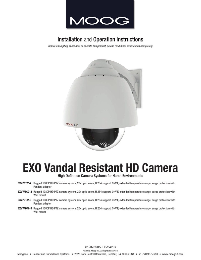
Moog EXVP7C2-2 User manual
Moog
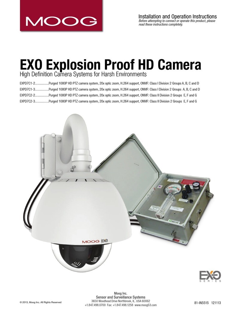
Moog EXPD7C1-2 User manual
Moog
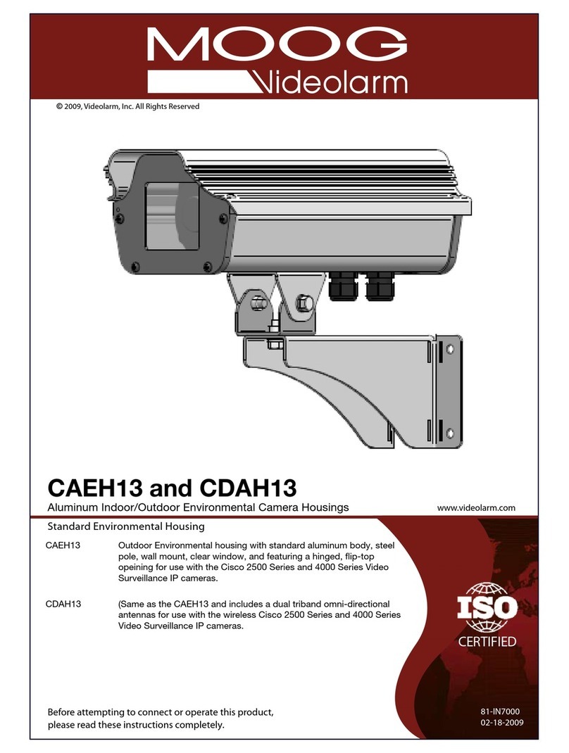
Moog CAEH13 User manual
Moog
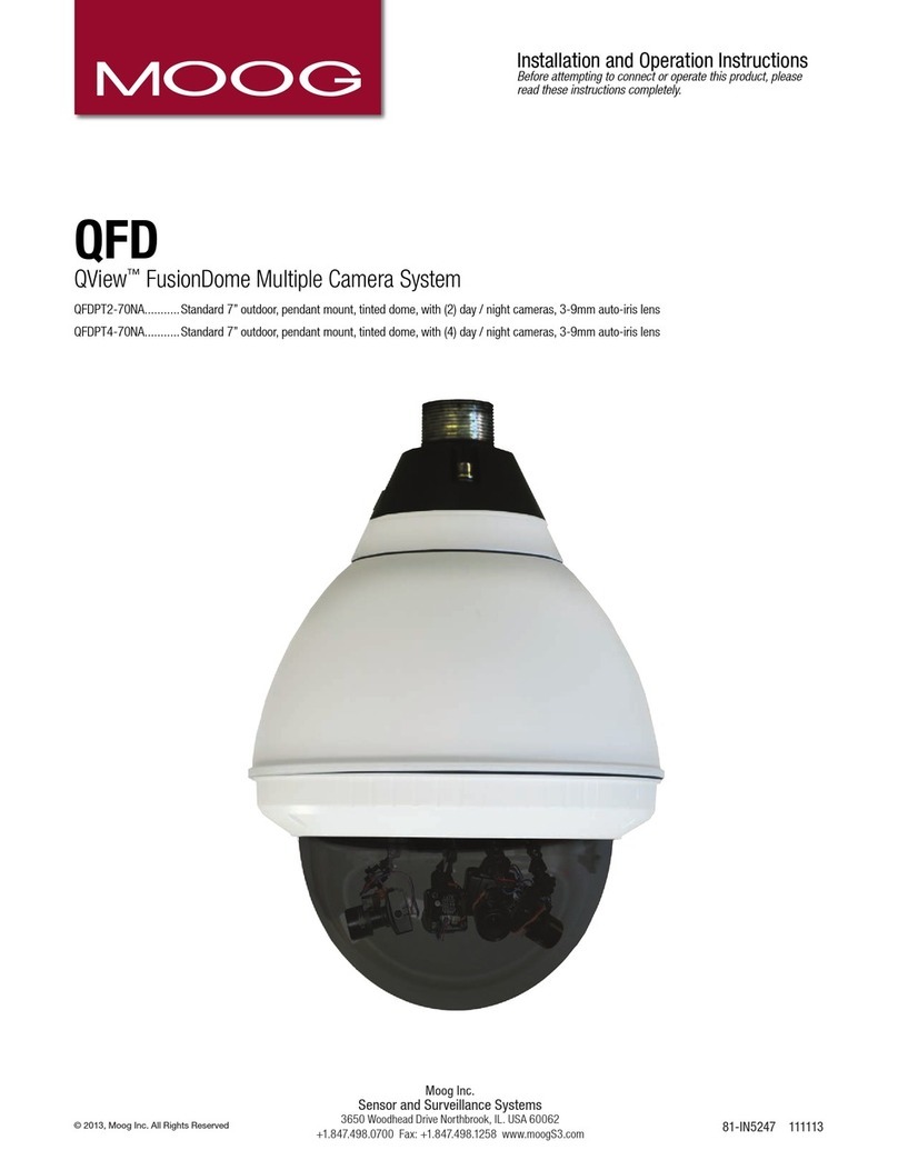
Moog QView QFDPT2-70NA User manual
