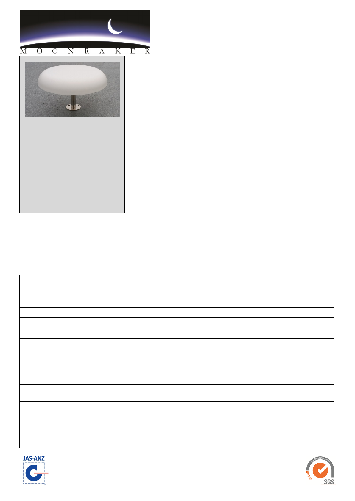
Moonraker TV Dome User manual

TV Dome
Land Mobile/Shipboard Omnidirectional TV and FM Radio
Reception Antenna System
Moonraker Australia Pty. Ltd. ABN 70 162 868 475
Tasmanian Technopark, 52 Innovation Drive, Dowsing Point, Tasmania, Australia 7010
Website: www.moonraker.com.au Tel: 61 (0)3 6273 1533 Fax: 61 (0)3 6273 1749 Email: [email protected]om.au
Specicaons subject to change. Issued : 23/06/16
The Moonraker TV/FM Dome Antenna is a compact active antenna system,
designed to provide improved reception of TV and FM signals in both the VHF and
UHF bands for both analogue and digital transmissions.
The sleek low profile design offers good looks, exceptional performance, reduced
wind resistance and internal cable connection.
The system is truly omnidirectional and features separate VHF and multiple UHF
arrays. These two arrays are suitably coupled via a built-in diplexer. Reception at
UHF frequencies is also optimised through the ability to receive both horizontally and
vertically polarised signals.
Completely sealed within a low profile ABS plastic radome for complete protection
from the marine environment, the antenna exhibits minimum pickup from other
shipboard communications equipment and is protected from lightning static
discharge. It may be roof mounted on buses, camper vans, and the like, providing a
low profile, streamlined and rugged installation. It is supplied with 6 metres of low
loss co-axial cable for connection to a remote control unit. There are two types of
control unit available.
The AM/FM unit comprises TV and AM/FM receiver outlets and input for a separate AM/BC receiving antenna for installations
where a combined AM/FM receiver is used. The AM/BC signal is combined with the dome’s FM signal and connected to the AM/FM
receiver outlet via the control unit. A suitable AM antenna is the Moonraker type 15BC/Marine with matching transformer or the
standard AM antenna on vehicles.
The TV/S unit is designed for installations where only a TV receiver outlet is required.
Frequency Range TV Bands: VHF 40-230 MHz; UHF 400-850 MHz; FM Band:76-108 MHz
Polarisation Horizontal at VHF; horizontal and vertical at UHF frequencies
Pattern Omnidirectional
Amplifier VHF 26dB UHF 34dB (replaceable unit)
Impedance 75Ω
Supply Voltage TV AM/FM: 12 or 24v; TV/S: 12v only. Reverse polarity protection. 3AG 250mA fuse . Negative earth
Current Drain 60 milliamps (approx)
Connections 75Ω co-axial via F type connector on antenna dome
Cable Supplied 6 metres x 6.5mm OD 75Ω high quality co-axial cable and F type connector , internal connection (no visible
cable run)
Radome White ABS plastic 300mm x 50mm (high)
Mounting Supplied with threaded stainless steel mounting pole 25.4mm x 130mm (height) and flange base mount.
Optional 300mm Mounting Pole Extension
Dimensions Standard Antenna : 300 x 200mm (high) With Optional Extension : 300 x 500mm (high)
Control Unit
Dimensions
TV AM/FM : 110 x 60 x 30mm
TV/S : 54 x 33 x 22mm
Weight Dome : 1.5kg Packed : 2.2kg Packed Dimension : 380 x 380 x 160mm
Warranty 12 Months
KEY FEATURES
Low Profile
High Performance
Fully Marinised
Long Service Life
Optional Extension Pole
A product of over 45 years antenna
design experience

TV Dome
Land Mobile/Shipboard Omnidirectional TV and FM Radio
Reception Antenna System
Moonraker Australia Pty. Ltd. ABN 70 162 868 475
Tasmanian Technopark, 52 Innovation Drive, Dowsing Point, Tasmania, Australia 7010
Website: www.moonraker.com.au Tel: 61 (0)3 6273 1533 Fax: 61 (0)3 6273 1749 Email: [email protected]om.au
Specicaons subject to change. Issued : 24/05/16
For best reception the Dome antenna should be installed as high as possible clear of metal objects such as masts, stays or
antennas, etc., which may distort the omnidirectional pickup pattern. It should not be in the line of fire of radars.
On vehicles, the dome should be mounted as high as possible above the roof. 100mm (4 in) should be used as a minimum guide.
Flush mounting is acceptable on a fibreglass roof. On ships using high power transmitting equipment the Dome should be
mounted as far as possible from transmitting antennas. Mounting may be by U bolts or hose clips clamped to a stub mast or other
structure or via the threaded flange mount provided.
The cable must be securely supported so that the cable weight does not hang on the dome connector. The cable may be
shortened or lengthened as required. To avoid ghosting, extension of the cable should be made by using an “in line” good quality
75W cable connector and 75Ω cable, preferably the same type as supplied with the antenna. All connections must be sealed to
prevent moisture ingress, particularly the coaxial connection in the base of the antenna. Use sealing tape provided.
The dome mounted amplifier is accessible by removing the 6 screws securing the cover plate on the base of the dome. The
amplifier connections and cover plate are sealed with a neoprene gasket and must be removed carefully. Do not open it unless
there is a problem. Service of the amplifier/control unit should only be carried out by a qualified technician. Replacement amplifier
units are available from Moonraker. When replacing the amplifier it must be resealed again, using grease such as petroleum jelly
on both side contact edges of the gasket. If using silicone, it is most important that only neutral cure silicone sealants are used as
other types corrode metals.
The control unit may be mounted in any convenient position located inside the vessel. For the AM/FM unit, mounting holes are
accessible by removing the unit lid. Connect the control unit battery cable to a suitable DC system. Wire with tracer is positive.
The unit will not work if polarity is reversed. If 110 or 240 volt AC operation is required use a 12 volt DC plug pack with a current
rating of at least 100 milliamps.
Power for the Dome amplifier is fed via the coaxial connecting cable. In the TV AM/FM control unit short term protection against
cable short circuit is provided by a fuse in the control unit, but long term short circuit may cause control unit overheating. The TV/S
unit’s fuse is external in line. Cables from control unit to receivers should be 75Ω and as short as possible.
If a dual AM/FM vehicle type receiver is fitted, special low capacity cables should be used for connection to the AM antenna. This
does not apply if the Moonraker 15BC receiving antenna is used. Both control units are reverse polarity protected. Coaxial cable
connection details are shown above.
WARNING : DO NOT WATCH TV WHILE DRIVING
to TV
Receiver
to AM/FM
Receiver
from Broadcast
Antenna
to/from Dome
Antenna
12-24V
TV AM/FM
Control Unit
1. Cut jacket through to the braid 12mm and remove outer PVC
2. Fold back the braid over the outer. Cut through the dielectric and foil 6mm from
end. Remove the dielectric and foil and expose 6mm of the centre conductor.
.
3. Slide on the connector, leaving 1.5 to 3mm of the centre conductor
protruding. The dielectric should also be flush with the bottom of the nut.
Then crimp the connector.
12mm 12m m
6mm
6mm
6mm
1.5-3mm
F Type Connector Assembly
12V
TV/S
Control Unit
to TV
Receiver
to Dome
Antenna
INSTALLATION INSTRUCTIONS

TV Dome
Land Mobile/Shipboard Omnidirectional TV and FM Radio
Reception Antenna System
Moonraker Australia Pty. Ltd. ABN 70 162 868 475
Tasmanian Technopark, 52 Innovation Drive, Dowsing Point, Tasmania, Australia 7010
Website: www.moonraker.com.au Tel: 61 (0)3 6273 1533 Fax: 61 (0)3 6273 1749 Email: [email protected]om.au
Specicaons subject to change. Issued : 24/05/16
In the event of the system not functioning:
Check that 12v or 24v is present at the input to the control unit; 12 volts only TV/S. Ensure that the polarity is correct (tracer is
positive)
Check fuse in TV AM/FM control unit (In-line fuse TV/S
Check for short circuit between braid and inner conductor of dome antenna cable; also check cables to TV receiver
The Moonraker TV Dome is a true omnidirectional antenna system and as such will receive signals from all azimuth directions.
This obviates the necessity to redirect the antenna as boat or vehicle heading changes. In some locations signals reflected from
cliffs, hills or nearby objects may be of similar strength to the direct signal. Since omnidirectional antennas will not discriminate
between direct and reflected signals, some picture deterioration, especially on the higher channels may occur in such locations.
Digital TV Reception
It is possible for some receivers to indicate there is no signal where an incoming digital signal is very strong. This can be easily
overcome by placing a variable or switchable attenuator (20dB) in the coaxial line between the control unit and TV receiver.
Analogue signals rarely suffer from this problem. A suitable attenuator is available from Moonraker.
INSTALLATION INSTRUCTIONS
Table of contents
Other Moonraker Antenna manuals
Popular Antenna manuals by other brands

Ubiquiti
Ubiquiti Prism AP-5-60 quick start guide

Sirius Satellite Radio
Sirius Satellite Radio SIRIUS Outdoor Home Antenna installation guide

Panasonic
Panasonic Ramsa WX-RP921 operating instructions

Intellian
Intellian v100GX Installation and operation guide

Cellink
Cellink ANT465 installation guide

D-Link
D-Link ANT24-0600 installation guide

Maxview
Maxview Precision I.D MXL019/55 User operating instructions

Channel Master
Channel Master 3022 installation instructions

MobileAccess
MobileAccess 1000 System Installation and configuration guide

Philex
Philex 27798RG user guide

Mobiltech
Mobiltech MOBILSAT 2016 DISMOUNT MANUAL

A.H. Systems
A.H. Systems AK-2G Operation manual