Flexible Sensors for Thermowell
Temperature Assemblies
Page 4
Flexible Sensors for Thermowell
Temperature Assemblies
Page 4
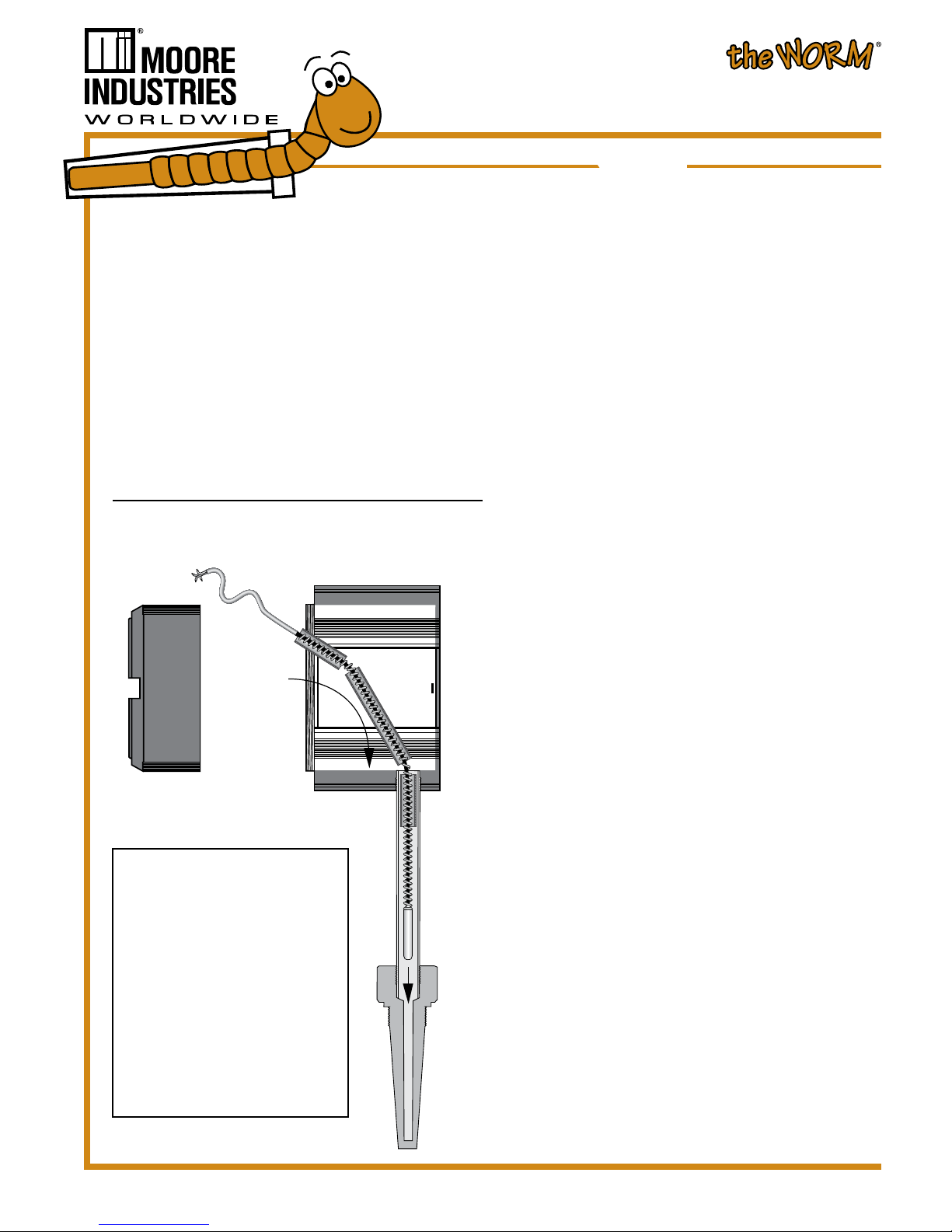
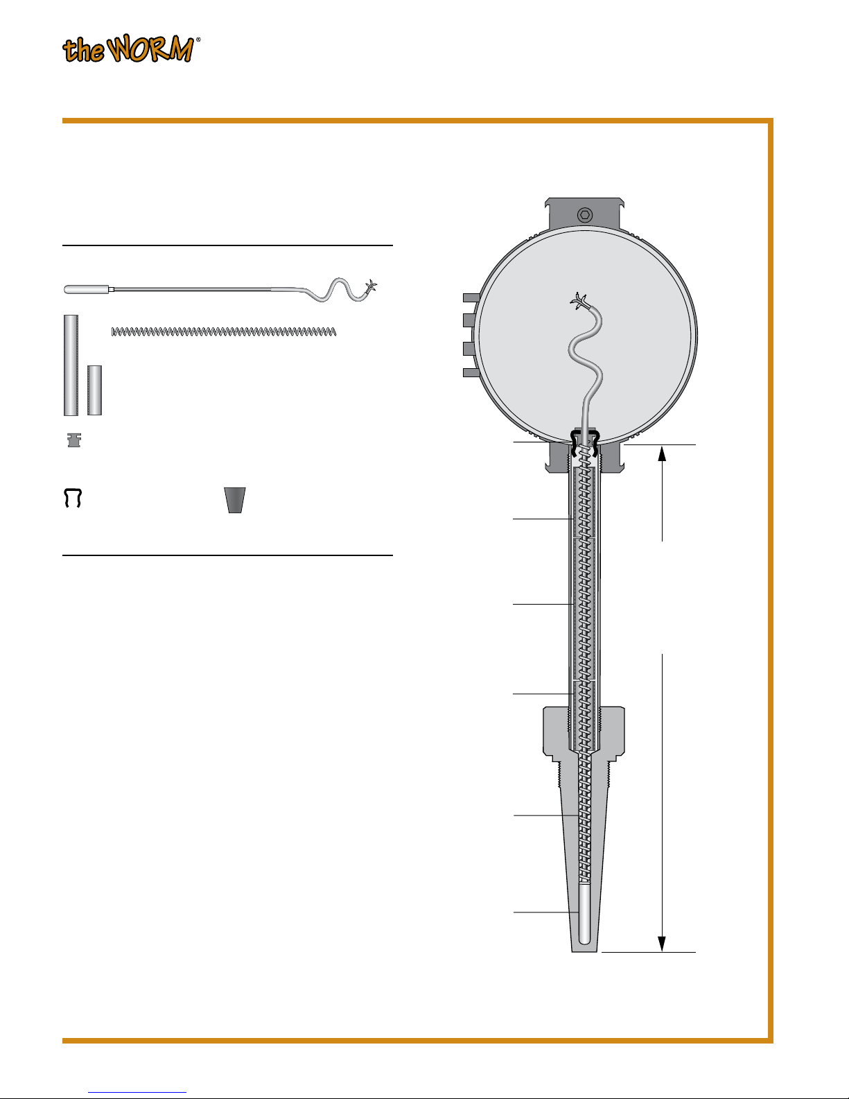
The WORM Sensor Kit
SEN3 Sensor Kit includes Three Complete "the WORM" Sensor Assemblies plus Spare Assembly Parts
SEN1 Sensor Kit includes One Complete "the WORM" Sensor Assembly plus Spare Assembly Parts
SEN Sensor Only; with Wire Jacket and Spring
Jacket and Spring Length (See Page 2 to Determine Total Sensor Insertion Length)
CL24 24-Inch Wire Jacket and Spring Length plus 6-8" lead wires (specify for total sensor insertion lengths of 22-inches and under)
CL36 36-Inch Wire Jacket and Spring Length plus 6-8" lead wires (specify for total sensor insertion lengths of 22-inches to 34-inches)
CL? Special Wire Jacket and Spring Length plus 6-8" lead wires - Replace "?" with length up to 120" (Specify in 0.25-inch increments)
Sensor Sheath Diameter
D25 Appropriate for 0.25-inch and 6mm diameter applications
D18 0.18-inch diameter applications for single elements (WS); for (WH), consult the factory
Sensor Sheath Material
S316 Stainless Steel 316; specify for measurements up to 760°C (1400°F)
INC Inconel (WHTCKG or WHTCKU sensor types only) up to 1,093°C (2,000°F) only
Sensor Type (see Sensor Specications on next page; consult factory for special WORM sensors)
RTD SENSORS:
WSPT14 Standard Platinum RTD; 4-Wire; 100 ohm; alpha = 0.00385
WS2PT14 Standard Platinum RTD; 4-Wire; 100 ohm (Dual Sensor); alpha = 0.00385
WSPT104 Standard Platinum RTD; 4-Wire; 1000 ohm; alpha = 0.00385
WHPT14 High Temperature Platinum RTD; 4-Wire; 100 ohm; alpha = 0.00385
WH2PT13 High Temperature Platinum RTD; 3-Wire; 100 ohm (Dual Sensor); alpha = 0.00385
WHPT104 High Temperature Platinum RTD; 4-Wire; 1000 ohm; alpha = 0.00385
WSN4 Nickel RTD; 4-Wire; 120 ohm
WSCU4 Copper RTD; 4-Wire; 10 ohm
THERMOCOUPLE SENSORS:
WSTC?G Standard, Replace ? with J, K, T or E Thermocouple, Grounded
WS2TC?G Standard, Replace ? with J, K, T or E Thermocouple, Grounded (Dual Sensor)
WSTC?U Standard, Replace ? with J, K, T or E Thermocouple, Ungrounded
WS2TC?U Standard, Replace ? with J, K, T or E Thermocouple, Ungrounded (Dual Sensor)
WHTC?G High Temperature, Replace ? with J, K, T or E Thermocouple, Grounded
WH2TC?G High Temperature, Replace ? with J, K, T or E Thermocouple, Grounded (Dual Sensor)
WHTC?U High Temperature, Replace ? with J, K, T or E Thermocouple, Ungrounded
WH2TC?U High Temperature, Replace ? with J, K, T or E Thermocouple, Ungrounded (Dual Sensor)
Assembly Options (not required)
-WW Wire Wound Option for Temperatures below -10°F or above +850°F to +1000°F
(For RTDs only)
-.04 1/3 DIN 0.04% High-Accuracy RTD Sensor
(Available on any WSPT104/WHPT104 RTD sensor types only)
-.06 Class "A" High-Accuracy RTD Sensor
(Available on any WS, WH, PT14 AND PT104 RTD sensor types only)
-10G 10G Low-intensity Vibration Sensor (See Sensor Specications)
-30G 30G High-intensity Vibration Sensor (See Sensor Specications)
The WORM Sensor Kit
[SEN]
Select one from each category to order a Sensor Kit:
SEN3 CL36
D25 S316 WSPT14 -.06 [SEN]
Model Number Example