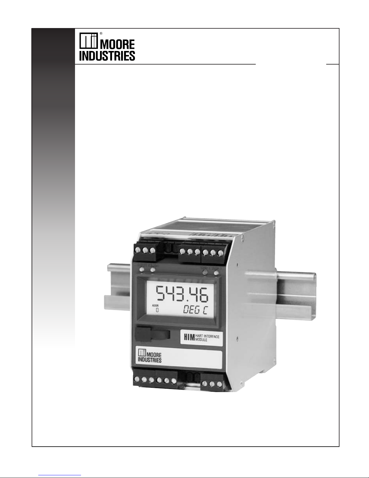
Moore Smart HIM HART User manual

HIM
HIM
November 2005
224-778-00C
Smart HART®Loop
Interface and Monitor
Smart HART®Loop
Interface and Monitor

2 The Interface Solution Experts
Table of Contents
The HIM ..............................................................................................................3
About this Manual ...............................................................................................................3
Specifications .....................................................................................................................4
HIM Dimensions ................................................................................................................. 5
Terminal Designations ........................................................................................................5
Configuring the HIM .........................................................................................6
Installing the HIM ..............................................................................................7
Installing the HIM into the Loop ........................................................................................... 7
Bench Checking the HIM ....................................................................................................9
PC Configuration Software............................................................................10
HART Parameters ............................................................................................................11
Display Parameters ..........................................................................................................13
Alarms Parameters ...........................................................................................................14
Analog Outputs Parameters ..............................................................................................16
Custom Curve Parameters ................................................................................................18
Scaling Parameters ..........................................................................................................19
Customer Service ...........................................................................................20
Appendix A: HIM MODBUS Feature .............................................................21

The Interface Solution Experts 3
HIM
Smart HARTLoop
Interface and Monitor
The HIM
The Moore Industries HIM HART Interface Module
unlocks the full potential of new and in-place HART
multivariable transmitters, valves, meters and other
smart instruments.
Converts HART to 4-20mA Signals
The HIM allows up to three additional analog process
variable measurements from a multivariable transmit-
ter or valve with no additional process penetrations.
Installed transparently across the 4-20mA instrument
loop, the HIM reads the HART digital process data that
rides on the loop wires. It converts the digital informa-
tion for up to three isolated analog (4-20mA) process
signals that are readily accepted by in-place control
systems, such as a DCS or PLC.
Provides Process and Diagnostic Alarms
Relay alarm trips (optional) can be individually user-set
either to trip when unwanted high/low process condi-
tions occur, or provide a diagnostic health warning to
alert of loop or instrument fault conditions.
Takes Advantage of Legacy Instruments
The device lets you leave existing smart HART trans-
mitters and valves in place, yet still take advantage of
all the information they have to offer.
Works with every Smart HART Device
The instrument can be programmed in minutes to inter-
face with every HART-compatible monitoring and con-
trol device.
About this Manual
Wherever you see a “
Note
”, “
Caution
”, or “
WARNING
”
pay particular attention.
•A“
Note
” provides information to help you in
avoiding minor inconveniences during
calibration, installation or operation of the HIM.
•A“
Caution
” provides information on steps to take
to avoid procedures and practices that could risk
damage to the HIM or other equipment.
•A“
WARNING
” provides information on steps to
take to avoid procedures and practices that could
pose safety risks to personnel.
Figure 1. The HIM Accepts a Digital HART Signal and Outputs Both Analog Signals and Alarm Relays
4-20mA Representing the
Primary Variable (Mass Flow)
HIM HART Interface Module
"Breaks Out" Data from
Smart HART Instruments
(HART Primary Master)
4-20mA Proportional to 2nd Variable (DP)
Control System
(DCS or PLC)
Smart HART
Multivariable
Mass Flow
Transmitter
4-20mA Proportional to 3rd Variable (P)
4-20mA Proportional to 4th Variable (T)
High Alarm in Response to 4th Variable (T)
HART Transmitter Fault Alarm
Flow
HART Communicator can
be connected anywhere
along the 4-20mA loop
(HART Secondary Master)
HART Digital Signal Carrying Primary,
Second, Third, Fourth Variable Process Data,
and Instrument Diagnostic Information

HIM
4 The Interface Solution Experts
Smart HARTLoop
Interface and Monitor
Specifications
Input Accuracy: Reflects
the accuracy of the HART
field device
Input Impedance: Transmit
Mode: 150 ohms;
Receive Mode: Less than
5kohms
Input Over-Range
Protection: ±5Vdc
ANALOG OUTPUTS
Output Accuracy: ±0.015%
of maximum output span
(20mA). Includes the
combined effects of linearity,
hysteresis, repeatability and
adjustment resolution.
Output Response Time:
<120ms, 10-90%
Isolation: 500Vrms channel-
to-channel isolation;
1000Vrms between case,
input, outputs and power
terminals, and will withstand
1500Vac dielectric strength
test for one minute with no
breakdown
Ripple: Less than 10mV
peak-to-peak when
measured across a
250 ohm resistor
Output Limiting: 130% of
span maximum; 125% of
span typical
Output Protection:
Transient protection on
output
Load Capability:
0-20mA, 1100 ohms
maximum
Load Effect: ±0.01% of span
from 0 to maximum load
resistance
Line Voltage Effect:
±0.005% of output span for a
1% change in line voltage
Input Fail Modes: PC
programmable to fail high, fail
low, hold last, hold last then
fail high, or hold last then fail
low (configurable hold time, 0-
60 seconds)
Output Limits on Input
Failure: 0-20mA: Fail Low to
0mA or Fail High to 23.6mA;
4-20mA: Fail Low to 3.6mA
or Fail High to 23.6mA;
X-20mA (0<X<4): Fail Low to
90% of XmA or Fail High to
23.6mA
Performance
Weight
Performance
(Continued)
Indicators
Indicators
(Continued)
Ambient
Conditions
+TX Power Supply: 24.0Vdc
±10%@24mA
ALARM OUTPUTS
Digital Response Time:
Defined by HART protocol as
500msec maximum in Normal
HART Mode; 333msec
maximum in HART Burst
Mode
Alarm Response Time:
Digital Response Time +
150msec (Defined as time
from the field instrument’s
reporting a fault until the HIM
alarm is tripped)
Alarm Trip Delay:
Programmable from 0-120sec
MODBUS OUTPUTS
Type: Standard MODBUS
RTU protocol interface over
RS485 (parameters as
specified in U.S. Standard
EIA-RS485)
Address Range:
Configurable from 1 to 247.
Unit will assume a MODBUS
address of 01 by default
Baud Rate: Interface
supports the following: 300,
600, 1200, 4800, 9600, 19.2k.
MODBUS interface will
support even, odd and no
parities. Unit will assume a
baud rate of 9600 and no
parity by default
Character Format: One start
bit, 8 data bits and one stop
bit
Data Format: User-
selectable Standard LSW
(Least Significant Word) or
Swapped MSW (Most
Significant Word). Unit will
assume Standard LSW by
default
Power Consumption:
2-3.5W, nominal; 4.5W
@24Vdc maximum for units
using transmitter excitation to
supply loop power a 2-wire
instrument
LCD Type: Two-line LCD;
Top Row, 10mm (0.4 in) high
black digits on a reflective
background; Bottom Row,
6mm (0.225 in) high digits
on a reflective background;
two-digit HART address
indicator
Specifications and information subject to change without notice.
Format: Top row is five
alphanumeric characters,
plus sign and decimal point;
bottom row is five
alphanumeric characters
Decimal Points: User-
selectable for 0, 1, 2 or 3
places after the decimal point
or automatically adjusting with
a four decimal point maximum
Range: -99999 to 99999
Minimum Display Span:
1.00
Display Update Rate:
100msec
LED Type: Dual color
red/green indicate:
INPUT LED: Whether (green)
or not (red) the HART input is
connected and functioning
properly
READY LED: Whether
(green) or not (red) the HIM is
initialized and operating
properly
TRIP 1 and 2 LED: Shows the
status of alarm off (green) or
alarm on (red)
Operating & Storage
Range:
-40°C to +85°C
(-40°F to +185°F)
Display Range:
-25°C to +85°C
(-13°F to +185°F)
Relay Range:
-25°C to +70°C
(-13°F to +158°F)
Relative Humidity:
0-95%, non-condensing
Ambient Temperature
Effect: ±0.0065% of
span/°C maximum
RFI/EMI Immunity
(Standard):
20V/m@20-1000MHz, 1kHz
AM, when tested according to
IEC1000-4-3-1995
RFI/EMI Immunity (with
-RF Option): 30V/m@
20-1000MHz, 1kHz AM, when
tested according to IEC1000-
4-3-1995
Noise Rejection: Common
Mode: 100dB@50/60Hz
567 grams (16 ounces)

The Interface Solution Experts 5
HIM
Smart HARTLoop
Interface and Monitor
Single Alarm (–1PRG)
Dual Alarm (–2PRG)
Relay 1
Table 1. Terminal Designations
NOTES:
1. The standard Single Alarm unit (1PRG) utilizes a DPDT relay.
2. Terminal blocks can accommodate 14-22 AWG solid wiring
(torque to 4 inch-pounds, maximum).
KEY:
+IN/–IN = Current input to HIM from HART device +TX = Transmitter Excitation Current
+I/–I Source = Analog Source Output +I/–I Sink = Analog Sink Output
A/B = MODBUS Output NO/NO# = Normally Open
NC/NC# = Normally Closed CM/CM# = Common
DC/DCC = 24VDC Connection (AO#) = Analog Output
INPUT / OUTPUT
HART Input, 2 Analog Outputs (2AO)
HART Input, 3 Analog Outputs (3AO)
HART Input, 2 MODBUS Oututs
and 1 Analog Output (MB1AO)
HART Input, 2 MODBUS Outputs (MB)
T1 T2 T3 T4 T5 T6 T7 T8 T9 T10 T11 T12
+TX
+TX
+TX
+TX
+IN
+IN
+IN
+IN
–IN
–IN
–IN
–IN
No Label +I Source
(AO2)
+I Source
(AO2)
A
MODBUS
2
A
MODBUS
2
ALARM RELAYS / POWER
NO1 CM1 NC1
–I Source
or
+I Sink
(AO2)
–I Source
or
+I Sink
(AO2)
B
MODBUS
2
B
MODBUS
2
–I Sink
(AO2)
–I Sink
(AO2)
S
MODBUS
2
S
MODBUS
2
B1 B2 B3 B4 B5 B6 B7 B8 B9 B10 B11 B12
+I Source
(AO1)
+I Source
(AO1)
A
MODBUS
1
A
MODBUS
1
DC
DC
–I Sink
(AO1)
–I Sink
(AO1)
S
MODBUS
1
S
MODBUS
1
Ground
Ground
–I Sink
(AO3)
–I Sink
(AO)
–I Source
or
+I Sink
(AO3)
–I Source
or
+I Sink
(AO)
+I
Source
(AO3)
+I
Source
(AO)
NO2 CM2 NC2
Relay 1
No Label
Relay 2
No Label
–I Source
or
+I Sink
(AO1)
–I Source
or
+I Sink
(AO1)
B
MODBUS
1
B
MODBUS
1
DCC
DCC
NO1 CM1 NC1 NO2 CM2 NC2
No Alarm No Label
DC Ground
DCC
65mm
(2.56 in)
138mm
(5.45 in)
133mm
(5.25 in)
100mm
(3.94 in)
HIM
HART INTERFACE
MODULE
READYINPUT
60.278
TRIP 2TRIP 1
COM
DEG C
0
ADDR
T1 T2 T3 T4 T5 T6 T7 T8 T9
T10 T11 T12
B1 B2 B3 B4 B5 B6 B7 B8 B9
B10 B11 B12
Figure 2. HIM Dimensions

HIM
6 The Interface Solution Experts
Smart HARTLoop
Interface and Monitor
Precision Load
Resistor
Multimeter or
Ammeter
Power
Supply
Personal Computer
PC Operating
System
Moore Industries
PC Configuration
Software
Communication
Cable
250 ohms, ±0.01%
Accurate to ±0.009% of span;
e.g. HP Model 3487A
24Vdc, ±10%
80386-based(or faster) IBM PC, or 100%
compatible; (Pentium recommended)
CD Drive
4Mb free RAM; 16Mb recommended
20Mb free disk space on hard drive
1 (one) serial port (COM 1, 2, 3 or 4)
Microsoft Windows®95, 98, 2000, ME, or
NT with Internet Explorer 4.0+
or
Microsoft Windows®NT with
Service Pack 3 or greater
Version 1.0 or higher, successfully
installed to the hard drive
Part Number: 803-053-26, or equivalent
Device Specifications
Table 2. Assembling the Necessary Equipment
Configuring the HIM
One of the benefits of the HIM is that there are no
internal or external controls to adjust or settings to
change. All operating parameters are set using the PC
Configuration software.
Once these software settings are made, they are
downloaded to the monitor in the form of a Configuration
File and stored in the unit’s non-volatile memory. You
can choose to save a backup copy of the file on your
PC hard drive or external media. The HIM communi-
cates with the PC through a proprietary communica-
tions cable to the PC’s serial (COM) port.
Begin by installing the PC Configuration Software.
Installing the PC Configuration Software
Refer to Table 2 for the equipment needed.
1. Insert the
Moore Industries Interface Solution
PC Configuration Software
CD into the CD drive
of the PC. Access the CD and open the
HIM
PC Configuration Software
folder.
2. Double-click the installation program located in
the folder. Follow the prompts to correctly
install the program.
Once the Configuration Program is installed on the PC,
the unit can be connected either into the loop or to test
equipment to simulate input and monitor output. With
the PC program, the user can then view and/or change
its operating parameters. To begin the process, connect
the HIM either into the loop (see
Installing the HIM into
the Loop
) or into a configuration setup (see
Bench
Checking the HIM
).

The Interface Solution Experts 7
HIM
Smart HARTLoop
Interface and Monitor
Installing the HIM
There are two methods for connecting the HIM for
configuration. The recommended method requires you
to install the instrument into the loop before it is
configured. The secondary method allows you to bench
check the HIM by attaching it to test equipment that
will simulate the input and monitor the output.
Installing the HIM into the Loop
Installation consists of physically mounting the unit,
grounding the instrument, and completing the electrical
connections. To install the HIM into the loop for
configuration, use the equipment in Table 2 to hookup
the HIM into the loop as shown in Figure 3 (without
using the HIM to power a transmitter) or Figure 4 (using
the TX terminal to power a transmitter). If you need a
complete terminal description, refer to Table 1.
Mounting
The HIM is designed to snap easily onto 32mm, G-type
(EN50035) or 35mm Top Hat (EN50022) DIN rails.
Electrical Connections
After mounting, you are ready to connect the HIM to
the loop. Each unit comes equipped with a transmitter
excitation terminal which allows it to supply power to
the monitored HART instrument, if necessary. Figures
2 and 3 show the connection diagrams for an HIM with
or without using the transmitter excitation current.
CE Conformity
Installation of any Moore Industries products that carry
the CE certification (Commission Electrotechnique)
must
adhere to the guidelines in
Installing the HIM
in
order to meet the requirements set forth in applicable
Figure 3. Installing a HIM Into the Loop Without Using the Transmitter Excitation (+TX) Terminal
READYINPUT TRIP 2TRIP 1
COM
0
ADDR
COMMON
NC (normally closed)
NO (normally open)
4-20mA
DCS
Sensor
Input
NO
NC
DC
GND
+
–
24Vdc
Power
Source
DCC
R
HART Multivariable
Field Instrument
(Temperature
Pressure, Level
and Flow)
Analog Output tied to
Any Process Variable
Event Recorder
HART Communicator
can be connected
anywhere on the loop
COM
+IN –IN
24Vdc
Power
+–
R must be > 250 and <1100 Ohms
1
2
3
4
5
6
7
8
9
0
.
—
➤
➤
➤
➤
➤
➤
➤
25.1
deg-c
80.1
20.3
50.7

HIM
8 The Interface Solution Experts
Smart HARTLoop
Interface and Monitor
Figure 4. Installing a HIM Into the Loop Using the Transmitter Excitation (+TX) Terminal
EMC (Electromagnetic Compatibility) directives
(EN55011, EN 50082-1, EN50082-2, etc.). Consult the
factory for the most current information on products
that have been CE certified.
Recommended Ground Wiring Practices
Moore Industries recommends the following ground
wiring practices:
• Any Moore Industries product in a metal
case or housing should be grounded.
• The protective earth conductor must be
connected to a system safety earth ground
before making any other connections.
• All input signals to, and output signals
from, Moore Industries’ products should be
wired using a shielded, twisted pair
technique. Shields are to be connected to an
earth or safety ground at the unit itself.
• The maximum length of unshielded input
and output signal wiring should be 2 inches.
Power Sourcing Parameters for General
Locations, Intrinsically Safe, and
Non-Incendive/Type N applications
In accordance with IEC 1010.1 Annex H
(all models), the input terminals must be
connected to and/or supplied from a certified
energy limiting Class 2 or a Separate Extra Low
Voltage (S.E.L.V.) power supply separated from
all mains by double/reinforced insulation.
READYINPUT TRIP 2TRIP 1
COM
0
ADDR
COMMON
NC (normally closed)
NO (normally open)
4-20mA
DCS
Sensor
Input
NO
NC
DC
GND
–
+
24Vdc
Power
Source
DCC
R must be > 250 and <1100 Ohms
R
HART Multivariable
Field Instrument
(Temperature,
Pressure, Level
and Flow)
Analog Output tied to
Any Process Variable
Event Recorder
HART Communicator
can be connected
anywhere on the loop
COM
+IN
+TX –IN
1
2
3
4
5
6
7
8
9
0
.
—
➤
➤
➤
➤
➤
➤
➤

The Interface Solution Experts 9
HIM
Smart HARTLoop
Interface and Monitor
Figure 5. Bench Checking the HIM Using the Transmitter
Excitation (+TX) Terminal to Power a Transmitter
Figure 6. Bench Checking the HIM Without Using the
Transmitter Excitation (+TX) Terminal to Power a Transmitter
Bench Checking the HIM
If you would like to configure the HIM before
attaching it to the loop, you need to hook it up
with the equipment listed in Table 1. Refer to
Figures 5 and 6 for instructions on how to bench
check the HIM either with or without taking
advantage of the Transmitter Excitation (+TX)
terminal. If you need further descriptions of the
terminals, see Table 2.
READYINPUT TRIP 2TRIP 1
COM
0
ADDR
For a HART Transmitter, the
resistor must be >250 and <1100 ohms.
For a HART Receiver, such as a
valve positioner, no resistor is necessary.
HART
Field Device
or
Simulator
Sensor
Input
Optional
Optional
Checks for
continuity
24Vdc
Power
R
+IN
NO
NC
DC
GND
COM
–IN
+
+–
–
+
–
+
–
Multimeter
Multimeter 24Vdc
Power
DCC
READYINPUT TRIP 2TRIP 1
COM
0
ADDR
Optional
Checks for
continuity
NO
NC
DC
GND
COM
+
–
+
–
Multimeter
Multimeter 24Vdc
Power
DCC
HART
Field Device
or
Simulator
Sensor
Input
Equipment Hook-Up
for HART field device using
Transmitter Excitation
R
+TX –IN
+IN
+
–
R must be > 250 and <1100 Ohms

HIM
10 The Interface Solution Experts
Smart HARTLoop
Interface and Monitor
The HIM PC Configuration Software can be used to
program all of the HIM’s parameters. Once the default
configuration has been saved, it is safe to program
other parameters. The PC Software is made up of
these sections:
1. HIM Status and Information Section–The left
side of the screen includes seven boxes that display
the different settings of the attached HIM.
Program Status–Displays the activity of the
connected HIM. It will show you if the unit is
Idle,
Uploading, Downloading, Monitoring
or
Searching.
HIM Device Info–Displays the individual charac
teristics of the attached HIM, such as its Identifi-
cation, Hardware and Software Revisions, and the
last date that the device was configured.
HIM Tag–A phrase used to identify a HIM.
Figure 7. HIM PC Configuration Software Screen
HIM Device Status–Displays how the HIM is function-
ing, giving a brief summary of any errors or displaying
OK
if it is operating normally.
HIM Displayed Data–this display mirrors what the at-
tached HIM is displaying.
Progress–This bar stays in motion any time the HIM
is monitoring, uploading or downloading.
Communication Status–monitors the PC Software’s
ability to communicate with the HIM.
2. HART/Display/ Alarms/Analog Outputs/Custom
Curve/ Scaling Tabs–These tabs change the right
side of the screen to allow you to set the appropriate
part of the HIM’s configuration. Refer to the associ-
ated pages in this document for additional information
on these tabs.
3. Menu Bar/Tool Bar– Dropdown menus and corre-
sponding icons allow you to perform various functions
throughout the PC Configuration Program.
1
2
3
PC Configuration Software

The Interface Solution Experts 11
HIM
Smart HARTLoop
Interface and Monitor
HART Parameters
To program the HART parameters, change the settings
in the
Communications Settings
box, then press
Quick
Set
. See the descriptions below of the various
sections of the screen.
HART Address
The
HART Address
is the address of the HART device
that the HIM will be monitoring.
Number of Retries
The
Number of Retries
can be set between 1 and 9,
and will determine how many times the HIM will
attempt to poll the HART transmitter (without success),
before it indicates a HART Fault condition.
Normal/Burst/Listen (Passive) Modes
The HIM can operate in one of four modes:
Normal
,
Burst
, or
Listen (Passive)
and
Listen (Specified Slave)
.
In each of these modes, the HIM attempts to find a
HART transmitter.
In
Normal
mode, the HIM polls the HART loop for a
transmitter, then polls the HART instrument twice per
second, requesting the current process status and the
HART instrument’s diagnostic status. The HART
instrument responds with the requested data.
In
Burst
mode, the monitored HART instrument is
programmed to continuously transmit its process
variable and health status. The HIM samples the
continuous HART data three times per second.
Listen (Passive)
mode allows the HIM to operate on a
loop that already has primary and secondary HART
masters. In
Listen
(Passive)
mode, the monitor
connects passively, continuously sampling HART data
from a smart instrument without affecting normal loop
operation. When using this mode, either the monitored
smart HART instrument must be set in
Burst Mode
or a
HART master must be continuously polling the smart
HART slave device.
The HART protocol allows for two communications
masters on the loop, a Primary and a Secondary.
Setting the HIM to function as the Primary HART
Master in the application means that any other HART
device in the loop must be configured either as a HART
Secondary Master (1 per loop) or as a HART Slave (up
to 16 per loop). Conversely, setting the HIM to function
as the Secondary HART Master allows other HART
devices to function either as a Primary Master or as
slaves. Configuring more than one device on a single
loop as a Primary or Secondary HART Master will
cause a communications failure.
Listen (Specified Slave)
When multiple HART instruments are present, the
Listen (Passive)
mode cannot be used because data
returned from one instrument will overwrite the data
previously stored in the HIM. If multiple HART slave
instruments are communicating on the loop, the HIM
will overwrite its internal HART data sets with the latest
device read from the bus, no matter where the data
originates. To allow selective monitoring on a multi-
instrument loop, and to allow multiple HIMs to be used
on a digital loop, the
Listen (Specified Slave)
feature is
used.
If the HIM is in “Listen” mode it is not a HART commu-
nication master and therefore is not in control of
communication. Other HART masters are controlling
the polling of slaves and the HIM can only “Listen”.
The HIM must be able to detect when it has not heard
from its assigned slave device so that it can declare a
“No HART” input and force outputs to the values
specified by the user. The HIM must therefore be told
to wait an appropriate amount of time for the slave
device to send its message before the HIM declares
“No HART”. This timing coordination is accomplished
with
Timeout Period
.
Timeout Period
is a value between 1 and 30sec and
must be greater than the period between polls by the
HART master of the Specified Slave. For example,
assume that there are five HART transmitters on the
same multi-drop loop as the HIM. The HART master is
configured to poll each device every second. It then
takes the HART master five seconds to repeat the poll
to the one device being monitored by the HIM. the HIM
Timeout Period
must be set at a value greater than five

HIM
12 The Interface Solution Experts
Smart HARTLoop
Interface and Monitor
seconds. In this example, we will use seven seconds.
The HIM then sees its slave device speak and waits
seven seconds for it to speak again. As long as the
HIM sees a new message from its slave device its
outputs are updated based upon the measured vari-
ables. If the slave device does not speak within the
seven second period, the HIM declares a “No HART”
situation and sends its outputs to the failed communi-
cations values.
To use this feature, proceed with the following steps:
1. Select the
Listen (Specified Slave)
button.
2. Enter your desired value into the
Timeout Period(s)
text box.
Factory default is 5 seconds. The maximum Timeout
Period is 30 seconds.
3. Set the exact slave address of the instrument you
wish to monitor. Click the
Set Slave Address
button.
This brings up the
HART Slave Device Long Format
Address Settings
screen (Figure 8). Enter the required
information into the appropriate text boxes.
The
Manufacturer’s ID
and
Device Type ID
for the
instrument that the HIM will listen to are available from
the HART Foundation website at www.hartcomm.org
and/or the instrument manufacturer.
Values obtained from the HART website are in HEX
code. The HIM does not use HEX code; you must
convert this value to Decimal code.
Figure 8. HART Slave Device Long Format Address Settings
Screen
To convert HEX to Decimal code, perform the
following steps:
Access the Calculator feature in Microsoft
Windows® by opening the
Start
menu. Next,
select
Programs
then
Accessories
and finally
Calculator
.
Ensure that the Calculator is in
Scientific
mode.
To do this, select the
View
dropdown menu
and choose
Scientific
.
Click the
Hex
radio button and enter the HEX
code value.
Next, click the
Dec
button and the value will be
converted into the Decimal value.
Enter the converted value into the proper param
eter.
The
Device ID Number
is the serial number of
the exact device to which the HIM will listen.
4. Once complete, press
OK
.
Download the information to your instrument once you
are finished.
Auto Clear Status Bit
Most HART instruments indicate when a device's
configuration has been changed. This indication
(status bit) can be reset by sending HART command
38–reset configuration changed. Checking the
Auto
Clear Status Bit
box causes the HIM to issue this
command whenever the HART instrument it is
monitoring has its configuration changed. However,
the HIM can also be set to alarm on this bit (see
Programming the Alarm Parameters
). If the HIM is
both set to alarm and to auto clear, then it will do
both–going into alarm mode and resetting that
indication.
Quick Read/Set
The
Quick Read
button causes the PC Configuration
Software to read the communications information from
the attached HIM; the
Quick Set
button causes the
software to configure the HIM’s communications
settings to match those of the PC Software.

The Interface Solution Experts 13
HIM
Smart HARTLoop
Interface and Monitor
HART Device Info
This box displays the identification and revision
information of the monitored HART instrument.
HART Device Status
The HART Device Status box displays the current
status of the monitored HART transmitter. In a small
double-box, the software displays the code (hex
number) associated with the status.
Variables
The device will monitor up to the first four HART
variables sent by your transmitter. This portion of the
screen displays those variables and the Loop Current.
HART Device Range & Limits
This portion of the screen displays the range and the
sensor limits of the monitored HART transmitter.
Display Parameters
The
Display
tab configures the HIM’s LCD display. To
program the Display parameters, change the settings in
the
Display Source
box, then press
Quick Set
. See
the following descriptions of the various sections of the
screen.
Figure 9. Display Tab
Toggle, Variable List
The
Toggle
checkbox causes the HIM to sequentially
display two HART variables in five second increments.
Directly below the
Toggle
checkbox are two list boxes
to select the variables that you would like to be
displayed. Notice that if you select a scaled variable,
it is important to check on the
Scaling
page to verify
that you have set all of the scaling parameters.
Use Custom Label
The
Custom Label
is used to display a calculated or
scaled variable. Clicking the
Use Custom Label
box
causes the HIM to always display the custom label as
Engineering Units (EGUs).
Precision
The
Precision
buttons allow you to change the number
of decimal places displayed by the HIM.
Quick Set
The
Quick Set
button programs the HIM with the
information on the Display page.
Display Format
The HIM reads the dynamic process variable supported
by HART sensors. Generally, the HIM’s LCD displayed
values range from -99999 to 99999. Occasionally,
these process variable values may extend past this
range. To improve the displayed readings, values
below -XXXXX and above XXXXX are translated into
exponential form. Below is an example of the appear-
ance of the display when certain values are sensed.
Value Display
12345 12345
1234500 1.23E06
-500000 -5.00E05

HIM
14 The Interface Solution Experts
Smart HARTLoop
Interface and Monitor
Alarms Parameters
The Alarms tab controls the programmable alarm
trip(s) option. This screen will be grayed out if the
attached HIM is not equipped with at least one alarm
trip. To program the Alarm parameters, change the
settings in the
Alarm1
and/or
Alarm2
box, then press
Quick Set
. The sections of the screen are described
below.
Trip/Fault Alarms
A
Trip Alarm
monitors a selected variable and trips
either when the variable exceeds a set value (Trip
High) or when the variable falls below a selected value
(Trip Low). The
Source
specifies which variable will be
monitored, while the
Trip Point
sets the point at which
the alarm will trip. After the alarm trips, the
Dead
Band
determines how far past the trip point the
variable will have to go before the alarm condition
returns to normal.
There are two types of Fault Alarms. A
HIM Fault
Alarm
monitors the health of the HART monitor. It will
trip whenever the internal error status word is set. For
example, if the HIM’s configuration file becomes
corrupt, this alarm will trip and the monitor will display
BAD_CONFIG. A
Field Device Fault Alarm
monitors
the health of the HART transmitter. This fault alarm
will trip for any of these eight malfunctions:
Figure 10. Alarms Tab
Device Malfunction (Bit 7)
Relay trips whenever it detects that a hardware error or
failure has occurred in the connected HART device.
Configuration Changed (Bit 6)
Relay trips whenever it detects that the connected
HART device has had its configuration changed.
Cold Start (Bit 5)
Relay trips whenever the power to the HART device is
interrupted. It will also trip during a HART Master
Reset or Self Test Command.
Additional Status (Bit 4)
Relay trips whenever the connected HART device
reports a condition requiring HART Command #48,
which is Read Additional Information. This indicates
that the instrument needs attention from a device with
full HART command capability.
Output Current Fixed (Bit 3)
Relay trips whenever the HIM detects that the
connected HART device’s output is no longer
responding to changes in its input, and is being held at
a predefined level.
PV Analog Output Saturated (Bit 2)
Relay trips whenever it detects that both its analog and
digital representations of the Primary Variable are
outside rated operating limits, and no longer reflect the
true sensor input.
Non-PV Out of Limits (Bit 1)
Relay trips whenever one of the HART ancillary
variables (second, third or fourth), is operating outside
the limits that can be effectively measured.
PV Out of Limits (Bit 0)
Relay trips whenever the HART Primary Variable is
operating outside the limits that can be effectively
measured.
Delay & Fail Safe
By entering a value in the
Delay
box, you can specify
how long (in seconds) the alarm condition needs to
exist before the alarm trips.
Failsafe
alarms (box
checked) de-energize when in alarm condition;
Non-Failsafe
alarms energize when tripped.

The Interface Solution Experts 15
HIM
Smart HARTLoop
Interface and Monitor
HART Additional Status Alarm Bits
HART Additional Status also called “More Status” and
“Command 48” is where device manufacturers install
the custom diagnostics for the specific device. For
your particular application, you may choose all of these
diagnostics to cause the HIM relay to trip or just one
diagnostic bit to trip the HIM relay (or any combination
in between). The manufacturer of the HART device will
be the source for the specific diagnostic information.
Selecting the
Field Device Fault Alarm
function in the
Alarms
screen allows you to enable the HIM to set
alarm states, when in fault mode, based on the bit
settings of the additional status information returned by
certain HART instruments. This provides flexibility to
the requirement of alarming on additional status infor-
mation.
Choosing this feature, you are given the ability to
specify the bit(s) on which to alarm. To access this
feature, check the
Additional Status
box. The
Edit
button will appear in the
HART Additional Status Bits
section of the screen. Clicking the
Edit
box brings up
the
Additional HART Status Alarm Bits Settings
window
(Figure 11). Check the box(es) that correspond to the
bits you wish to use; click
OK
.
Download the information to your instrument once you
are finished.
Figure 11. Additional HART Status Alarm Bits Settings Window
Read & Quick Set Buttons
The
Read
button causes the PC Configuration Software
to read the alarm information from the attached HIM;
The
Quick Set
button causes the software to configure
the HIM's alarm settings to match those currently
entered in the PC Software.

HIM
16 The Interface Solution Experts
Smart HARTLoop
Interface and Monitor
Analog Outputs Parameters
The HIM comes with either two (–2AO) or three (–3AO)
analog outputs. The
Analog Outputs
tab allows you to
specify which HART variable is to be monitored as the
source of the analog output, the input range and output
range, and how the output will react when the variable
input is out of range. To program the Analog Outputs
parameters, change the settings in the
Output1/2/3
boxes, then press
Quick Set
. See the descriptions
below of the various sections of the screen.
Source
Source
defines the variable that the analog output will
monitor. Notice that selecting one of the scaled
outputs will require you to make changes to the
Scaling
tab, and selecting the Custom Curve option will
require you to make changes to the
Custom Curve
tab.
Input/Output Range
The
Input
or
Output Range
defines the range of the
source input and the range of the analog output.
These two sets of fields can be used to scale the
HIM’s output.
Figure 12. Analog Outputs Tab
For example, you have a vortex flow meter with an
imbedded RTD that measures the process
temperature, and that temperature is assigned to the
HART Secondary Variable. The full range of the RTD
sensor is from –400°F to +1760°F, but your flow
stream will always be between 0° and 400°F. To scale
the analog output, for Output 1, set the
Source
as SV.
Set the
Input Range
to 0° and 400°F, and the
Output
Range
to 4mA to 20mA. Click
Quick Set
to download
the new configuration file to the HIM.
Output Current Box
The
Output Current
Box on the
Analog Outputs
Tab
displays up-to-the-second information on the value, in
mA, of the analog output.
Fail Mode
The
Fail Mode
setting determines how the HIM will
respond when its monitored input fails. If
Fail Mode
is
set to
High
and the measured input goes out of range,
or any detected error occurs in the HART transmitter,
the analog output will output a 23.6mA signal. If Fail
Mode is set to
Low
and the measured input goes out of
range, or any detected error occurs in the HART
transmitter, the analog output will output a signal that
is 90% of the lower range value below 4mA; it will
output 0mA if the lower range is set to 0mA.
If
Fail Mode
is set to
Hold Last
, the HIM will continue
to output the last value it recorded before the input
failed. If
Fail Mode
is set to
Hold Last Then High
or
Hold Last Then Low
, the HIM will continue to output the
last value recorded for a set amount of time (according
to Hold Last Duration box), then either fail high or fail
low, respectively.
Quick Set Button
The
Quick Set
button causes the software to configure
the instrument’s analog output settings to match those
currently entered in the PC Software.
Trim Button
The
Trim
button brings up the Trim Menu, allowing you
to set the device’s output to match the reading of the
loop. Refer to the
Programming the Trimming
Parameters
section of this manual for more
information.

The Interface Solution Experts 17
HIM
Smart HARTLoop
Interface and Monitor
Configuring Analog Output Trimming
The
Analog Output Trimming
section of the software
allows you to match the HART monitors analog output
to the output measured by a calibration device. This
will require a calibrated multimeter, such as a HP Model
3478A or equivalent, accurate to ±0.009%.
Note:
Trimming the analog output of the monitor
nullifies any scaling that may have been
performed in the
Scaling
tab.
User Trimming
To trim the device, attach a multimeter to the analog
output, then click the
Fix Output at Low Point
button.
Read the value on the multimeter, enter it into the
Measured Output Loop Current
portion of the
Trimming
box, and press
Trim
. Repeat this sequence until the
analog output matches the minimum point (4mA for a
4-20mA output) when you click the
Fix Output at Low
Point
button.
After the low point is trimmed, press the
Fix Output at
High Point
button. Read the value on the multimeter,
enter it into the
Measured Output Loop Current
portion
of the
Trimming
box, and press
Trim
. Repeat this
sequence until the analog output matches the
maximum point (20mA for a 4-20mA output) when you
click the
Fix Output at High Point button
.
When finished, press the
Unfix Output
button.
Figure 13. Trimming Window
Fix Current Utility
The
Fix Current Utility
allows you to force the HIM to
output any current value from 0-20mA. This can be
used to match the calibration of your other equipment.
To fix the current, simply enter the value in the
Current
box (in mA) that you want the HIM to output, and click
Fix Output
. When you are finished, make sure to
press the
Unfix Output
button so that the HIM can
return to normal operation.

HIM
18 The Interface Solution Experts
Smart HARTLoop
Interface and Monitor
Custom Curve Parameters
The custom curve tab allows you to set up a custom
curve of up to 128 points. A custom curve can either
be created from scratch or loaded from a previously
created comma separated value (.csv) file. To
program the Analog Outputs parameters, change the
settings in the
Custom Curve
tab, then press
Download
Table
. See the descriptions below of the various
sections of the screen.
Mode
Check the
Enabled
box to begin programming the
custom curve.
Source Variable
The
Source Variable
defines the variable that the
custom curve will calculate. Notice that if you select a
scaled variable, you may need to click on the
Scaling
tab and verify the settings for your scaled variable.
Quick Set
The
Quick Set
button causes the software to configure
the HIM’s custom curve settings to match those
currently entered in the PC Software.
Figure 14. Custom Curve Tab
Custom Curve Variable
The
Custom Curve Variable
displays up-to-the-second
information on the value of the Custom Curve. Press
the
Monitor
button to display the variable information.
Custom Curve
The middle section of the screen displays the custom
curve table. After enabling custom curve mode and
setting the variable to be monitored, continue by
selecting the number of points for the curve. Enter the
actual linearization points into the custom curve table,
inserting the source variable into the X Column, and
the corresponding data (i.e. the °C, °F, Gallons, PSIG,
Millimeters, etc.) into the Y Column.
Note:
When entering data in the linearization table, make
sure that you enter a number into every open cell.
Custom Curve File
These buttons allow you to manipulate custom curve
files, including the important
Save Table
command that
will save a table to your hard drive.
Upload Table
Moves a custom curve file from the connected HIM to
the PC Software for editing or storage.
Download Table
Configures the HIM by downloading the custom curve
table from the PC Software to the HIM.
Save Table
Saves a displayed custom curve table to memory on
your computer’s hard drive.
Load Table
Loads a previously saved custom curve table.
Clear Table
Clears the displayed custom curve table.
When you have finished changing all your settings,
download the information to the HIM using the
Download Table
button. If you have selected a scaled
variable, you should also click on the
Scaling
tab and
set the scaling parameters.

The Interface Solution Experts 19
HIM
Smart HARTLoop
Interface and Monitor
Full
Primary
Variable
range
(in PSI)
Control
level
range
(50% to 100%
of total level)
Digital
Pressure
Transmitter HART Monitor
(120 PSI)
HART
Signal
Loop Display
(reads 0-100%
of control
level)
Controller maintaining
control from 50-100% of full scale
(60-120 inH 0/2.15-4.3 PSI).
4-20mA from HART Monitor
should represent 60-120
inH 0.
4-20mA
Signal
4-20mA
Signal
2
2
Figure 15. Scaling Tab
Figure 16. The HIM’s Scaling feature works to get the most out of your existing process instruments
Scaling Parameters
The
Scaling
tab allows you to configure the values for
scaled variables. To scale the selected variable, enter
the values into the appropriate boxes, then click on the
Transfer
menu and click
Download
to transfer the new
scaled values to the HIM. (If any scaled variable was
selected in the
Display, Alarm or Analog Outputs
tabs,
then the corresponding scaled variable section will
become active for editing).
The HIM’s versatile scaling feature has many possible
applications, as is shown in the illustration below.
Suppose you are using a digital pressure (DP)
transmitter to measure the level of a tank in either
centimeters/inches or PSI. Since the tank is only 300
centimeters (10 feet) high, the full range of the primary
variable (PV) output from the DP transmitter is 0-4.3
PSI. You want to display the full level range (in
centimeters/inches of water) on the HIM. You also
need to control the level from 50% to 100%, since the
tank must be at least 50% full at all times. Finally,
your existing loop indicator and level controller needs
4-20mA to represent 150 to 300 centimeters (60 to 120
inches) of water. How do you do this?
Scaling Illustration
1. Since you want to display the full level range in
inches of water (in H2O) on the HIM, and the HIM is
reading PSI as the primary variable, first go to the
Display
tab and select
Scaled PV
as your display
source.
2. Go to the
Scaling
tab and set up the
PV Zero
and
PV Full
values, and the
Scaled PV Zero
and
Full
values.
PV Zero
would be 0 (PSI) and
PV Full
would
be 4.3 (PSI).
Scaled PV
would correlate to zero being
0 in H2O and full being 120 in H2O. The HIM should
now (after downloading) display the full range in
in H
2
O
.
3. To manipulate the HIM’s analog output, go to the
Analog Outputs
tab. Select
Scaled PV
as the Output 1
source. Since you need to control the level from 50%
to 100%, the
Input Range
should be 60 to 120 in H2O
and the
Output Range
should be 4mA to 20mA.

HIM
20 The Interface Solution Experts
Smart HARTLoop
Interface and Monitor
Customer Support
Moore Industries is recognized as the industry leader
in delivering top quality to its customers in products
and services. We perform a battery of stringent quality
assurance checks on every unit we ship. If any Moore
Industries product fails to perform up to rated specifi-
cations, call us for help. Our highly skilled staff of
trained technicians and engineers pride themselves on
their ability to provide timely, accurate and practical
answers to your process instrumentation questions.
Factory phone numbers are listed on the back cover of
this manual.
If problems involve a particular instrument, there are
several pieces of information that can be gathered
before you call the factory
that will help our staff get
the answers you need
in the shortest time possible.
For fastest service, gather the complete model and
serial number(s) of the problem unit(s) and the job
number of the original sale.
Table of contents