5
2. Main Harness Connection
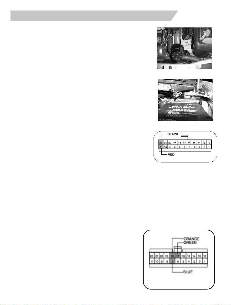
8. Locate the YELLOW 20-gauge wire located in cavity #4 of the ignition switch
connector. This wire should measure +12v only when the vehicle is cranked with
the key.
9. Using wire cutters, cut the 20-gaugeYELLOW wire in half.Try to create this cut
about 2 or 3”s away from the ignition switch connector, remove more harness
tape wrap if necessary.
THE FOLLOWING CONNECTIONS MUST BE
MADE INTHE PROPER POLARITY.IFTHE
WRONGWIRES ARE CONNECTED THEVE-
HICLE WILL NOT START AND THE CONNEC-
TIONSWILL HAVETO BE REVERSED. READ
THE FOLLOWING CAREFULLY.
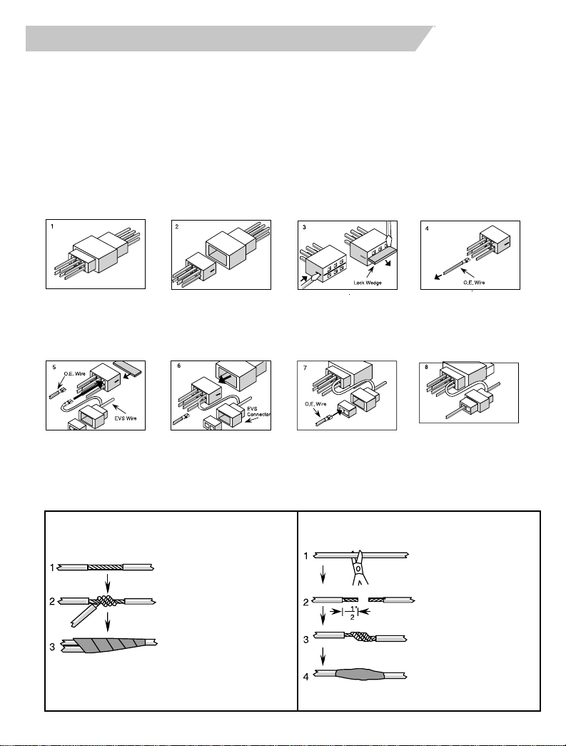
10. Using the supplied RED butt connectors, splice
the EVS 20-gauge YELLOW/BLACK wire to the
previously cut 20-gauge YELLOW wire coming
from the ignition switch connector.
(Follow crimping procedure outlined on page 4).
11. Splice the EVS 20-gauge YELLOW wire to the previously
cut YELLOW wire which goes toward the wire harness.
FIG. 2.3
Ground Connection
1. Locate a vacant area of metal on the support brace to use as a chassis ground.
2 Attach the EVS BLACK ground wire to the area chosen by inserting the supplied
screw through the ground ringlet and into this area.
3. Make sure the ringlet is securely tightened.
Dome Light Connection
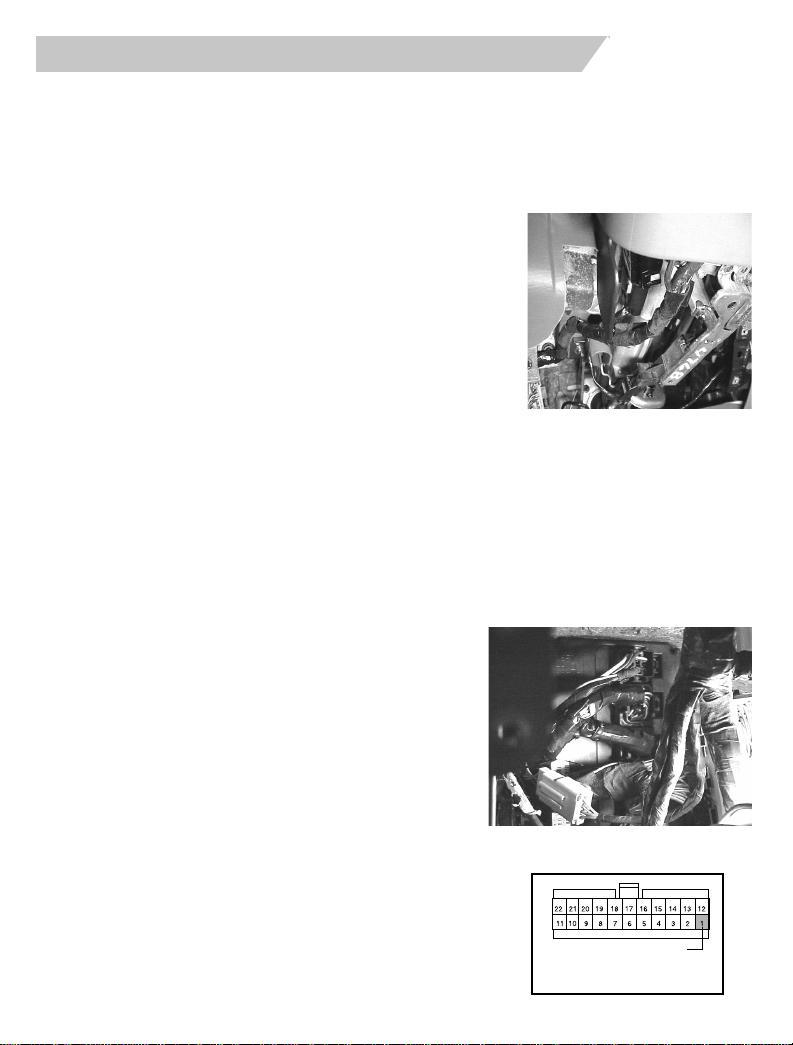
1. Locate the BCM against the drivers side
bulkhead. Locate the 34-way C2 connector
which is the second connector from the top
on the BCM. (FIGURE 2.4)
2. Locate the 20-gauge YELLOW/ORANGE wire
located in cavity #25 of the C2 connector.This
wire will register 12V+ when the dome light is
on and ground when the dome light is off.
3. Center splice the singular EVS 20-gauge
YELLOW/ORANGE wire that is tapped to the
EVS harness into this vehicle’s YELLOW/
ORANGE wire.
(Follow the Center Splice procedure on page 3)
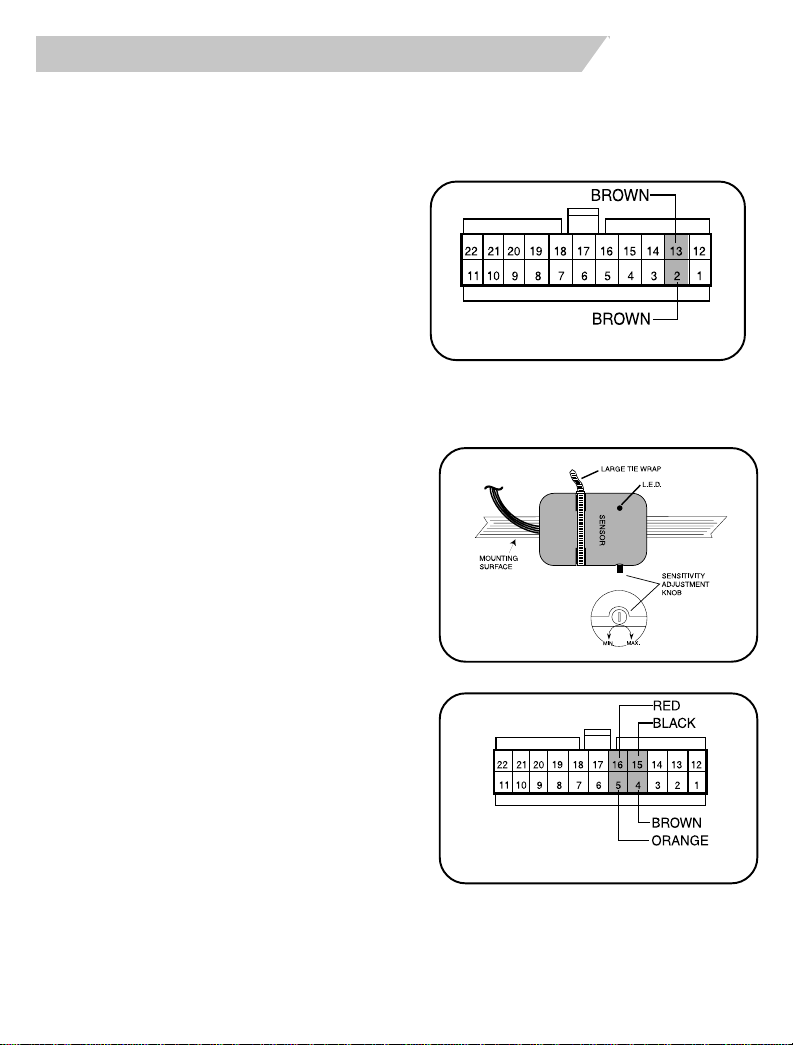
4. Insert the terminal on the other end of the EVS
wire into pin position #1 of the EVS module’s
22-way connector. (see diagram on page 13)
FIG. 2.4
Viewed from wire end
DOMELIGHT