Mopar K6860631 User manual

K6860631 – WI-FI ROUTER
Click on the desired vehicle to take you directly to the vehicle specific
instructions.
08 RAM/09 RAM HEAVY DUTY – REGULAR CAB
08 RAM/09 RAM HEAVY DUTY – QUAD CAB
09 RAM – REGULAR CAB
09 RAM – QUAD/CREW CAB
300/CHARGER/CHALLENGER
CALIBER
COMMANDER
COMPASS
DAKOTA
DURANGO/ASPEN
GRAND CHEROKEE
JOURNEY
MINIVAN
NITRO/LIBERTY
PACIFICA
PATRIOT
PT CRUISER
SEBRING SEDAN/AVENGER
SPRINTER
WRANGLER
Aug 08, 2008 K6860631 Rev. 1

1
WI-FI ROUTER
DODGE RAM-REGULAR CAB
PROCEDURE STEPS:
NOTE: Using a test light, verify the cigarette lighter outlet being used is ignition switched. Power must not be
supplied with the ignition in the OFF position.
NOTE: If equipped with the mini console, proceed to step 4. If equipped with a full console, proceed to step 11.
1. Disconnect and isolate the battery negative cable.
2. Using a trim stick C-4755 or equivalent, disengage the
retaining tabs and remove the lower bezel panel (2).
3. Remove the two lower screws (3) securing the cup
holder or close out panel (2) to the instrument panel
(IP).
Aug 08, 2008 K6860631 Rev. 1

2
4. Onvehicleswithaminiconsole, removethe4WD gear
shift boot, if equipped.
5. If equipped with a manual transmission, remove the
transmission gear shift lever extension.
6. Remove the console inserts, if equipped.
7. Remove the bolts (2) that secure the rear console (1)
to the floor panel.
8. Lift up the rear of the floor console to clear the gear
shift lever, if equipped.
Aug 08, 2008 K6860631 Rev. 1

3
9. Remove the bolts (2) and separate the front console
(3) from the floor.
10. Separate the front clips (1) and remove the mini con-
sole.
11. On vehicles with a full center console, using a trim
stick C-4755 or equivalent, separate the seven front
console bezel clips (2), lift up the back of the bezel (1)
and remove.
12. Remove the bolts (1) and lift the rearof the base up to
release the front guide pins (5).
13. Remove the front base (2).
Aug 08, 2008 K6860631 Rev. 1

4
14. Remove the screws (2).
15. Using a trim stick C-4755 or equivalent, disengage the
retainer clips that secure the instrument panel center
bezel (1) to the instrument panel.
16. Disconnect the wire harness connectors and remove
the center bezel from the vehicle.
17. Open the glove box (1).
18. Release the two glove box stops (2) and lower the
glove box downward past the stops.
19. Disengage the glove box hinges from the instrument
panel and remove the glove box.
20. Using a trim stick C-4755 orequivalent, disengage the
retaining tabs of the cowl trim panel (1) from the re-
tainer clips (2) in the door sill (3).
21. Pull the cowl trim panel rearward and remove it from
the vehicle.
Aug 08, 2008 K6860631 Rev. 1

5
22. Remove the three bolts (1) that secure the rear stor-
age compartment (2) to the floor panel (3) and remove
the storage compartment from the rear cab trim panel
(4).
23. Remove the cap (1) and then the bolt (2) that secures
the seat belt (3) to the top of the B-pillar (4) and posi-
tion the seat belt out of the way.
24. Using a trim stick C-4755 or equivalent, disengage the
retaining tabs that secure the upper B-pillar trim panel
(5) to the B-pillar and remove the trim panel.
25. Remove the bolt (2) that secures the seat belt (1) to
the bottom of the B-pillar (4) and position the seat belt
outoftheway.
26. Using a trim stick C-4755 or equivalent, disengage the
retaining tabs that secure the lower B-pillar trim panel
(3) to the B-pillar.
27. Remove the seat belt from the lower B-pillar trim panel
through the slot provided and remove the trim panel.
Aug 08, 2008 K6860631 Rev. 1

6
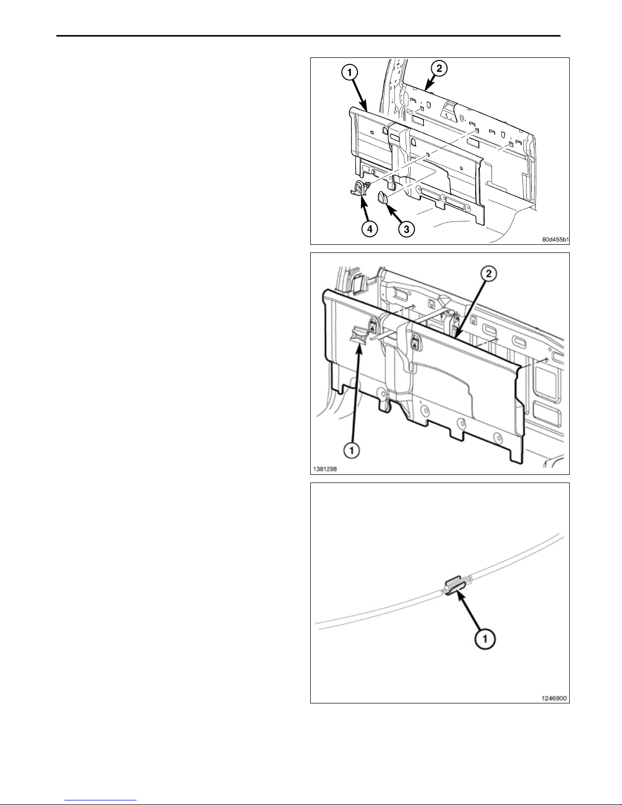
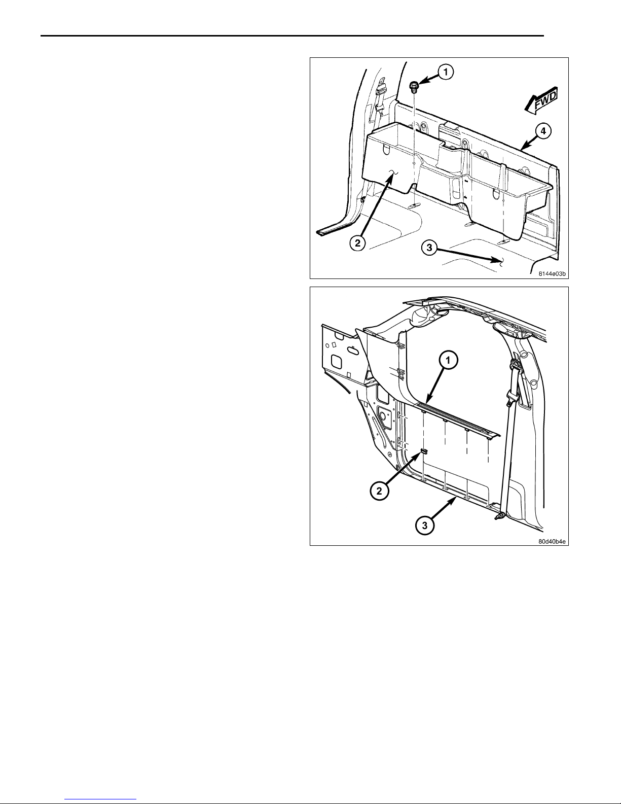
28. Remove the utility hooks (3) from the rear cab trim
panel (1) and remove the trim panel.
29. Install the Wi-Fi router to the rear cab trim panel with
the provided materials.
30. Make a small cut in the rear cab trim panel and route
the Wi-Fi router connector through
31. Place the rear cab trim panel into position in the vehi-
cle.
32. Connect the wire harness to the Wi-Fi router connec-
tor.
33. Route the wire harness down the back of the rear
panel to the door sill.
34. Firmly seat the rear panel and install the utility hooks
to the rear panel.
35. Continue to route the wire harness along the passen-
ger side, under the glove box opening and behind the
center stack.
36. Locate the cigarette lighter outlet wiring harness.
37. Cut each wire and remove 13 mm (0.5 in.) of insula-
tion from each wire that needs to be soldered/spliced.
38. Place a piece of supplied adhesive lined heat shrink
tubing on one side of each cut wire. Insure the tubing
will be long enough to cover and seal the entire sol-
dered area.
CAUTION: Do not use acid core solder.
39. Solder the supplied fused pigtail to Wi-Fi power har-
ness power wire.
Aug 08, 2008 K6860631 Rev. 1

7
40. Placethestrandsofthepowersidewiresoverlappingeach
other inside of the splice clip (1).
41. Usingcrimpingtool(1), Mopar®p/n05019912AAorequiv-
alent, crimp the splice clip and wires together.
42. Repeat the previous two steps for the ground side wires.
CAUTION: Do not use acid core solder.
43. Solder (3) the connection (2) together using rosin core sol-
der (1).
Aug 08, 2008 K6860631 Rev. 1

8
44. Center the heat shrink tubing (2) over the solder joint and
heat using a heat gun. Heat the joint until the tubing is
tightly sealed and sealant (1) comes out of both ends of
the tubing.
45. Place the lower B-pillar trim panel (3) into position and
engage the retaining tabs that secure the trim panel to
the B-pillar (4).
46. Route the seat belt through the slot provided in the
B-pillar trim panel.
47. Install the bolt (2) that secures the seat belt (1) to the
bottom of the B-pillar (4).
48. Place the upper B-pillar trim panel (5) into position and
engage the retaining tabs that secure the trim panel to
the B-pillar (4).
49. Install the bolt (2) that secures the seat belt (3) to the
top of the B-pillar (4) and Install the cap (1).
Aug 08, 2008 K6860631 Rev. 1

9
50. Installthe storagecompartment(2)tothe rear cab and
install the three fasteners (1) that secure the rear stor-
age compartment to the floor panel (3).
51. Place the cowl trim panel (1) into position and engage
the retaining tabs to the door sill (3).
Aug 08, 2008 K6860631 Rev. 1

10
52. Engage the glove box (1) hinges to the instrument
panel.
53. Press the two glove box stops (2) and raise the glove
box upward.
54. Close the glove box.
55. Positionthe instrumentpanelcenterbezel(1)near the
IP and connect the wire harness connectors.
56. Install the instrument panel center bezel onto the IP
and fully engage the retainer clips.
57. Install the two lower screws (2).
58. If necessary, install the close out panel (2) or
cupholder and install the screws (3).
Aug 08, 2008 K6860631 Rev. 1

11
59. Install the lower bezel panel (2) ensuring the retaining
tabs engage.
60. If equipped with a mini console, position the console
and seat the front clips (1) fully.
61. Install the bolts (2).
Aug 08, 2008 K6860631 Rev. 1

12
62. Install the bolts (2) that secure the rear console (1) to
the floor panel.
63. Install the inserts.
64. Install the gear shift lever extension.
65. Install the 4WD gear shift boot, if equipped.
Aug 08, 2008 K6860631 Rev. 1

13
66. If equipped with a full console, Install the front base
(2).
67. Seat the rear of the base to engage the front guide
pins (5) and Install the bolts (1).
68. Install the console bezel (1) and engage the seven
front console bezel clips (2).
69. Connect the battery negative cable.
Aug 08, 2008 K6860631 Rev. 1

1
WI-FI ROUTER
DODGE RAM-QUAD CAB
PROCEDURE STEPS:
NOTE: Using a test light, verify the cigarette lighter outlet being used is ignition switched. Power must not be
supplied with the ignition in the OFF position.
NOTE: If equipped with the mini console, proceed to step 4. If equipped with a full console, proceed to step 11.
1. Disconnect and isolate the battery negative cable.
2. Using a trim stick C-4755 or equivalent, disengage the
retaining tabs and remove the lower bezel panel (2).
3. Remove the two lower screws (3) securing the cup
holder or close out panel (2) to the instrument panel
(IP).
Aug 08, 2008 K6860631Rev. 1

2
4. Onvehicleswithaminiconsole, removethe4WD gear
shift boot, if equipped.
5. If equipped with a manual transmission, remove the
transmission gear shift lever extension.
6. Remove the console inserts, if equipped.
7. Remove the bolts (2) that secure the rear console (1)
to the floor panel.
8. Lift up the rear of the floor console to clear the gear
shift lever, if equipped.
Aug 08, 2008 K6860631Rev. 1

3
9. Remove the bolts (2) and separate the front console
(3) from the floor.
10. Separate the front clips (1) and remove the mini con-
sole.
11. On vehicles with a full center console, using a trim
stick C-4755 or equivalent, separate the seven front
console bezel clips (2), lift up the back of the bezel (1)
and remove.
12. Remove the bolts (1) and lift the rear of the base up to
release the front guide pins (5).
13. Remove the front base (2).
Aug 08, 2008 K6860631Rev. 1

4
14. Remove the screws (2).
15. Using a trim stick C-4755 or equivalent, disengage the
retainer clips that secure the instrument panel center
bezel (1) to the instrument panel.
16. Disconnect the wire harness connectors and remove
the center bezel from the vehicle.
17. Open the glove box (1).
18. Release the two glove box stops (2) and lower the
glove box downward past the stops.
19. Disengage the glove box hinges from the instrument
panel and remove the glove box.
20. Using a trim stick C-4755 or equivalent, disengage the
retaining tabs of the cowl trim panel (1) from the re-
tainer clips (2) in the door sill (3).
21. Pull the cowl trim panel rearward and remove it from
the vehicle.
Aug 08, 2008 K6860631Rev. 1

5
22. Using a small flat-bladed tool, carefully open the two
fastener covers (2) located on the grab handle (1).
23. Remove the two bolts (3) that secure the grab handle
to the B-pillar and remove the grab handle.
24. Remove the cap (1) and the bolt (2) that secures the
seat belt (3) to the top of the B-pillar (4) and position
the seat belt out of the way.
25. Using a trim stick C-4755 or equivalent, disengage the
retaining tabs that secure the upper B-pillar trim panel
(5) to the B-pillar and remove the trim panel.
Aug 08, 2008 K6860631Rev. 1

6
26. Using a trim stick C-4755 or equivalent, disengage the
retaining tabs that secure the lower B-pillar trim panel
(1) to the B-pillar (2).
27. Remove the seat belt (3) from the lower B-pillar trim
panel through the slot provided and remove the trim
panel.
28. Remove the cap (1) and then the bolt (2) that secures
the seat belt (3) to the top of the C-pillar (4) and posi-
tion the seat belt out of the way.
29. Using a trim stick C-4755 or equivalent, disengage the
retaining tabs that secure the upper C-pillar trim panel
(5) to the C-pillar and remove the trim panel.
30. Remove the bolt (3) that secures the seat belt (2) to
the bottom of the C-pillar (4) and position the seat belt
outoftheway.
31. Using a trim stick C-4755 or equivalent, disengage the
retaining tabs that secure the lower C-pillar trim panel
(1) to the C-pillar.
32. Remove the seat belt from the lower C-pillar trim panel
through the slot provided and remove the trim panel.
Aug 08, 2008 K6860631Rev. 1
Table of contents
Other Mopar Wireless Router manuals