manuals.online logo
Brands
  1. Home
  2. •
  3. Brands
  4. •
  5. MOPEKA
  6. •
  7. Accessories
  8. •
  9. MOPEKA Pro Sensor User manual

MOPEKA Pro Sensor User manual

This manual suits for next models

1

Other MOPEKA Accessories manuals

MOPEKA Pro M1017 Series User manual

MOPEKA

MOPEKA Pro M1017 Series User manual

MOPEKA Standard Sensor Technical Document

MOPEKA

MOPEKA Standard Sensor Technical Document

Popular Accessories manuals by other brands

Quincy lab 140AE-1 operating manual

Quincy lab

Quincy lab 140AE-1 operating manual

HomePro ZIR000 user manual

HomePro

HomePro ZIR000 user manual

DOL 20SCR Technical user guide

DOL

DOL 20SCR Technical user guide

RAB Smart Task installation manual

RAB

RAB Smart Task installation manual

Kemppi KMS 300 quick guide

Kemppi

Kemppi KMS 300 quick guide

Stearns 57,500 Series Installation and service instructions

Stearns

Stearns 57,500 Series Installation and service instructions

iGuzzini TWILIGHT COPENAGHEN manual

iGuzzini

iGuzzini TWILIGHT COPENAGHEN manual

Adelaide Annexe & Canvas Avan Deluxe installation guide

Adelaide Annexe & Canvas

Adelaide Annexe & Canvas Avan Deluxe installation guide

OHAUS 5000 instruction manual

OHAUS

OHAUS 5000 instruction manual

HOME8 WLS1300 quick start guide

HOME8

HOME8 WLS1300 quick start guide

MAXBOTIX MaxSonar quick start guide

MAXBOTIX

MAXBOTIX MaxSonar quick start guide

ioSmart iSmart56 Installation and user guide

ioSmart

ioSmart iSmart56 Installation and user guide

Focusrite Scarlett 18i8 user guide

Focusrite

Focusrite Scarlett 18i8 user guide

Velleman ED38105 user manual

Velleman

Velleman ED38105 user manual

JumpSport SkyBounce user manual

JumpSport

JumpSport SkyBounce user manual

Prima-Temp PRIYA Instructions for use

Prima-Temp

Prima-Temp PRIYA Instructions for use

Tefcold BC85I-BC85I W user manual

Tefcold

Tefcold BC85I-BC85I W user manual

Vaisala WMS302 user guide

Vaisala

Vaisala WMS302 user guide

manuals.online logo
manuals.online logoBrands
  • About & Mission
  • Contact us
  • Privacy Policy
  • Terms and Conditions

Copyright 2025 Manuals.Online. All Rights Reserved.

www.mopeka.com
Page 1of 14
M200004E
Pro Sensor Models M1017--- (Propane)
INTENDED USE OF THE M1017 SENSOR IS TO MEASURE THE AMOUNT OF LIQUID PROPANE INSIDE A PROPANE
TANK MEETING THE SPECIFATIONS BELOW, UNDER THE CONDITIONS LISTED BELOW.
THIS DEVICE IS INTENDED FOR OUTDOOR USE ONLY.
WARNING
USE OF THIS DEVICE IN A MANNER OTHER THAN STATED IN THIS MANUAL, MAY RESULT IN IMPAIRMENT OF
THE DESIGNED SAFETY PROTECTION AND THUS AN UNSAFE CONDITION.
SPECIFICATIONS
MEASUREMENT METHOD
Ultrasonic
FLUID
Propane
TANK TYPES
Steel or Aluminum
Not intended for use on composite cylinders.
TANK SIZES
Horizontal and Vertical Tanks Up to 48-inch fluid height
Envelope Dimensions
73 mm Diameter x 7.3 mm Thickness (2.87 x 0.29 inches)
Mounting location
Tank Bottom
Steel Tanks use magnet version
Aluminum tanks require collars attached with pre-applied adhesive
Other mount devices also available
Suitable for these locations
CLASS I, DIVISION 2, GROUP D
CLASS I, ZONE 2, GROUP IIA
OPERATING TEMPERATURE RANGE
-30° TO 55°C
TEMPERATURE CODE
T6
BATTERY
ONE, CR2032 COIN CELL (3V)
HUMIDITY RANGE
0 - 100%
MAX ALTITUDE
4000m
WARNING
EXPLOSION HAZARD-BATTERIES MUST ONLY BE CHANGED IN AN AREA FREE OF IGNITIBLE CONCENTRATIONS.
WARNING
THIS DEVICE IS NOT TO BE REPAIRED OR OTHERWISE MODIFIED.
MOPEKA PRODUCTS LLC
MAILING ADDRESS: 445 FM 1983, COLORADO CITY, TX 79512
www.mopeka.com
[email protected]m
www.mopeka.com
Page 2of 14
M200004E
OPERATING INSTRUCTIONS
Smart Device/App Users
1. Go to your app store. Search for Mopeka Tank Check app and install.
2. Launch the app. When it starts it will automatically start a search for Mopeka ✓sensors.
www.mopeka.com
Page 3of 14
M200004E
3. Press and hold SYNC button until sensor appears on app. (up to 10 seconds)
4. The sensor will then appear on your app as a new device.
5. Sensor is now Sync’d. You may now proceed to installing the sensor on the tank.
www.mopeka.com
Page 4of 14
M200004E
For LPG Tank ✓Display Users:
6. Pull the battery protection strip completely out of display and discard. This will turn on the display.
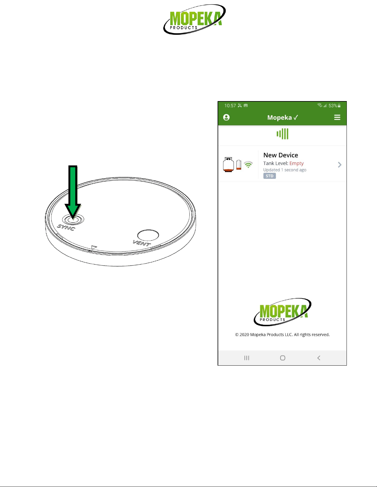
7. Hold one of the buttons on your Display until the lights for that button start flashing (approx 5
seconds). Release button when lights start flashing.
8. Press and hold SYNC button until sensor (up to 10 seconds) until the display lights stop flashing. The
sensor is now synced with the display.
9. Repeat steps to sync the second sensor to the 2nd button/gauge of the display.
10. Both sensors are now sync’d to the display.
11. The display is programmable, allowing you to choose a tank size of 20 lb (5 gal), 30 lb (7.5 gal), or 40 lb
(10 gal).
12. It is automatically set to 20 lb from the factory. To change the size setting, hold the button of the
scale you want to change for 10 seconds. (After 5 seconds lights will start flashing, as when syncing.
But continue to hold button until lights change again.)
13. At 10 seconds, a single light will appear. Continue to hold button. The single light will scroll between
red, yellow, and green. When the color corresponding to your tank size appears, release the button.
Your tank size is now set.
•Red = 20 lb
•Yellow = 30 lb
•Green = 40 lb
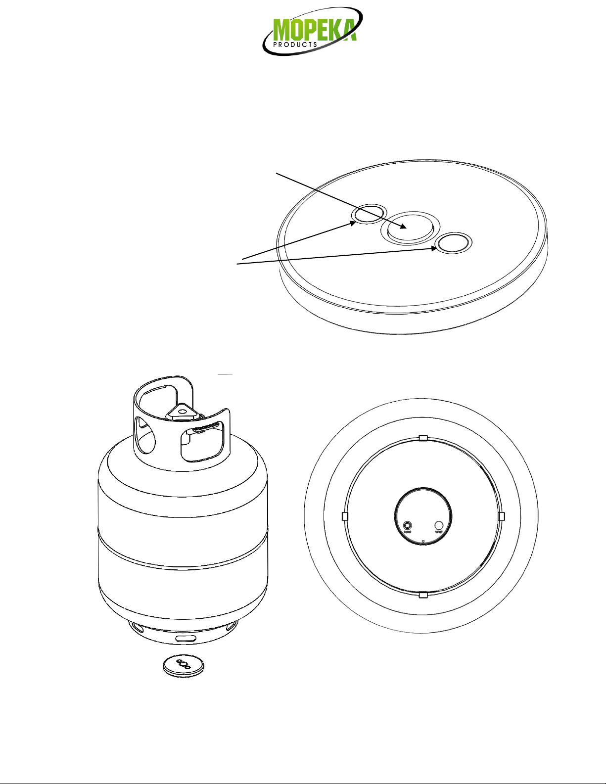
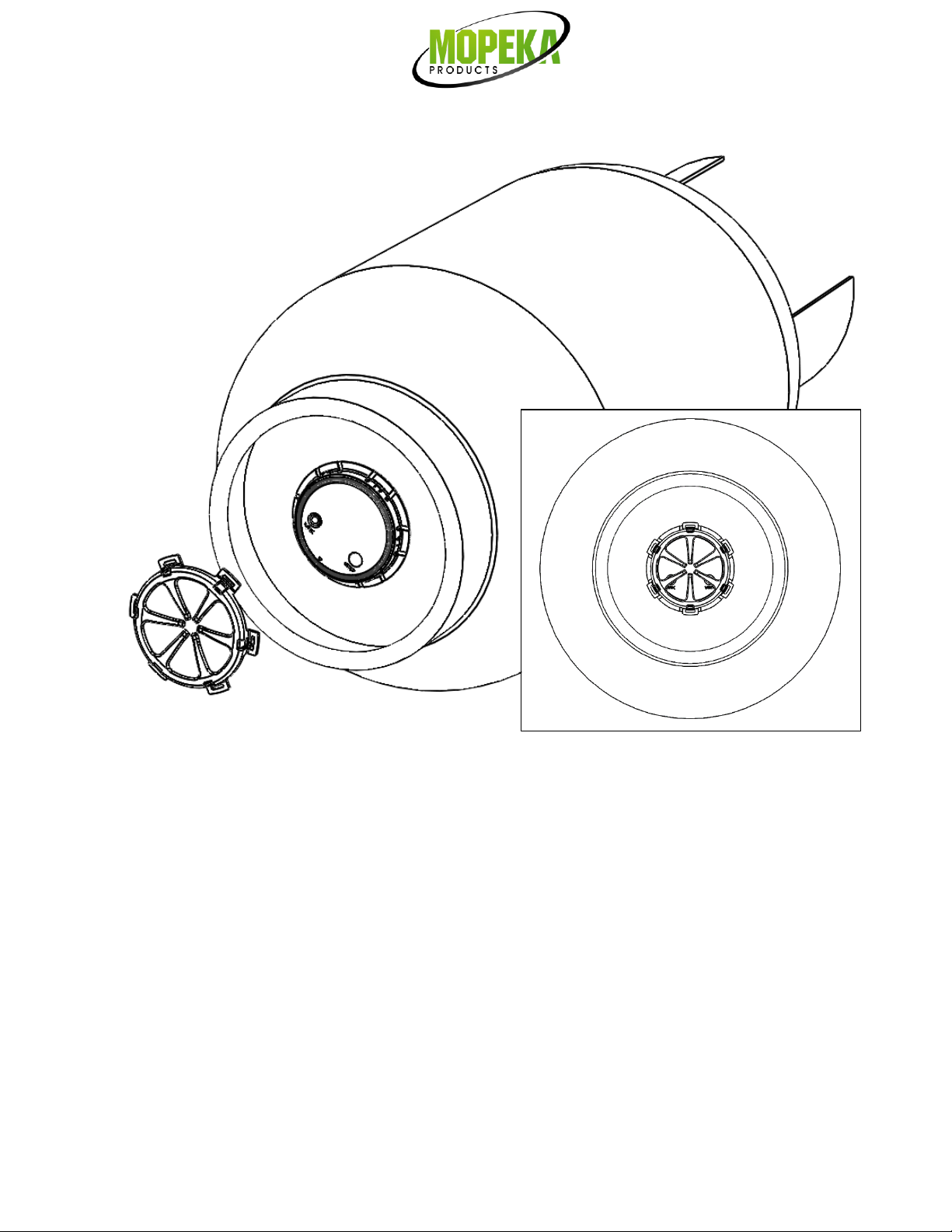
14. You are now ready to install the sensor(s) on the tank(s).
www.mopeka.com
Page 5of 14
M200004E
Install Sensor on Tank-Vertical Cylinders
15. Clean the bottom of the tank of any debris, excess paint, and rust.
16. If your tank sits directly on the ground or other flat surface, then install the spacers to the bottom of
the foot ring of your tank. This will provide adequate space and improved wireless range for the sensor.
Steel Tanks:
17. The sensor mounts to the bottom center of the tank using magnets. The rubber pad between the
magnets must make good contact with the tank, with no contaminants in between and must be aligned to
the bottom center of the tank.
18. Apply a generous amount of the supplied sonic grease directly to the rubber pad before attaching sensor
to the tank.
19. Install sensor on tank such that rubber pad is aligned with the bottom, center of tank.
www.mopeka.com
Page 6of 14
M200004E
Magnets
Rubber Pad
www.mopeka.com
Page 7of 14
M200004E
Aluminum Tanks:
20. The sensor mounts to the bottom center of the tank using the collar set.
21. The collar set has pre-applied 2-sided adhesive. The tank must be properly prepared or the collar will not
adhere.
22. The tank must be thoroughly cleaned with soap and water.
23. Allow the water to dry, then clean the tank with an alcohol pad or similar, to remove all grease.
24. Lay the collar set in the center of the tank bottom, and mark as needed to guide the final installation of
the collar onto the tank.
25. Separate the collar pieces, peel the backing paper from the base piece, and stick to the tank per your
markings. Thoroughly press the ring all the way around. Pressure is required to force the tape to adhere
to the tank.
26. Apply a generous amount of the supplied sonic grease directly to the rubber pad before attaching sensor
to the tank.
27. Install sensor inside the collar, rubber pad against tank.
28. Now snap the retaining ring onto the collar set.
www.mopeka.com
Page 8of 14
M200004E
29. Return the tank to the upright position. Check that the tank is on a level and flat surface or otherwise is
level with ground. A tilt can degrade the quality of the measurement.
30. After a few seconds, up to a few minutes, the propane will settle, and the readings will stabilize.
www.mopeka.com
Page 9of 14
M200004E
Install Sensor on Tank-Horizontal Cylinders
31. If installing on a horizontal tank, place the sensor on center, bottom of tank, with rubber pad and
magnets against tank as shown. It is important to place it on the center of tank so that sensor is
horizontal, or sensor reading quality can be poor.
www.mopeka.com
Page 10 of 14
M200004E
32. Use the Sensor Position option on the sensor’s home page in the app, as needed, to ensure proper position on
the tank. When installed correctly, the sensor will be level to the horizon. The Sensor Position tool works like a
bubble level. The dots move as the sensor is tilted from horizontal level position. If the dots in the tool do not
line up to the center of the graphic, adjust the sensor position until it lines up. Note: If sensor must be
repositioned multiple times, sonic grease may need to be reapplied.
BOTTOM VIEW OF TANK
(Green line is centerline of tank. Magnets and rubber pad should
all be on tank centerline.)