Morgan MBH-825 Triblaze User manual

E-mail: electrical.appliance@dksh.com
www.morgan.my
Market Expansion
Services by
www.dksh.com.my
facebook.com/morganappliances
USE MANUAL
Built-in
Hob MBH-825 Triblaze

3
C O N T E N T S
3
4
5
6
7
8
11
SAFETY PRECAUTIONS
OPERATING INSTRUCTIONS
AIR VA VE ADJUSTMENT
CARE & C EANING
TROUB E SHOOTING
INSTA ATION
PARTS IDENTIFICATION & SPECIFICATIONS
SAFETY PRECAUTIONS
EAD ALL INST UCTIONS CA EFULLY before using the product & keep the manual
for future reference.
To maintain the efficiency and safety of this appliance, we recommend you the
following:
• Only contact the manufacturer-authorized Service Centres.
• Always insist on using only genuine spare parts.
• Never use any gas other than the recommended gas.
• Have your appliance connected to the gas supply performed only by qualified persons.
• Ensure that the controls are turned off when you have finished cooking and when not in
use.
• Turn off the gas supply after the fire is turned off.
• Maintain and keep the hob clean as a grease or fat build-up from cooking can cause a
fire.
• Keep children away from the appliance during use.
• Exercise caution to avoid heat/steam burns when using.
• Never use the appliance to heat up anything other than food.
ARNING! IN THE EVEN OF A CHIPPED PAN OR OTHER PAN FIRE:
1.Turn off the burners.
2.Cover the pan with a fire blanket or damp cloth, this will smother the flames and
extinguish the fire.
3. eave the pan to cool for at least 60 minutes before moving it.

54
OPERATING INSTRUCTIONS AIR VALVE ADJUSTMENT
• The position of the corresponding gas burner is indicated on each control knob.
• The burners differ in size and power. Choose the most appropriate one for the diameter
of the cookware being used.
• The burner can be regulated with the corresponding control knob by using one of the
following settings:
LIGHTING A BURNER
• Press the corresponding knob all the way and then turn it in the counter-clockwise
direction to the “HIGH” setting, keeping it pressed until the burner is lit.
CAUTION: If the burner accidentally goes out, turn off the gas using the control
knob and attempt to light it again after 1 minute.
TURNING OFF A BURNER
• Turn the knob in the clockwise position until it stops (at the “
I
” setting)
To keep the flame in optimal* condition, it is essential to adjust the air valve. Back-fire
burning** can cause severe damage to hob parts. Hence, the hob should be turned off
immediately when it back-fires.
NOTES:
* Blue flame colour, without red/yellow flame & stable combustion without back fire-
burning.
** Back fire-burning refers to fire burning inside the burner.
IMPO TANT
• Adjust the air valve by moving the valve handle in clockwise/anti-clockwise direction until
there is no flame separated from the fire holes and flame is in optimal condition.
• The air valve is installed at the bottom of the hob which is a round-shaped gear iron
plate as illustrated.
Pictures A & B indicate two types of air valves used on different types of hobs (pictures
for reference only).
Pictures A Pictures B

6 7
TROUBLE SHOOTING
USER MAINTENANCE INSTRUCTIONS
This appliance requires little maintenance and contains no user-serviceable parts.
Any servicing requiring disassembly other than cleaning must only be performed by
a qualified appliance repair technician.
IMPO TANT!
1. Before cleaning or performing maintenance on the appliance, disconnect it from the
gas and power supply and allow it to cool before proceeding.
2. It is recommended to have the appliance cleaned regularly to extend its functionality.
3. Do not use steam equipment to clean the appliance.
CARE & CLEANING INSTRUCTIONS
1. Wash the enamelled parts and the glass top with warm water.
2. Do not use metal kitchen utensils or abrasive cleansers or corrosive cleansing agents
as this may damage the finishing.
3. Wash the removable parts of the burner frequently with warm water and mild
detergent, ensuring caked-on residues are removed.
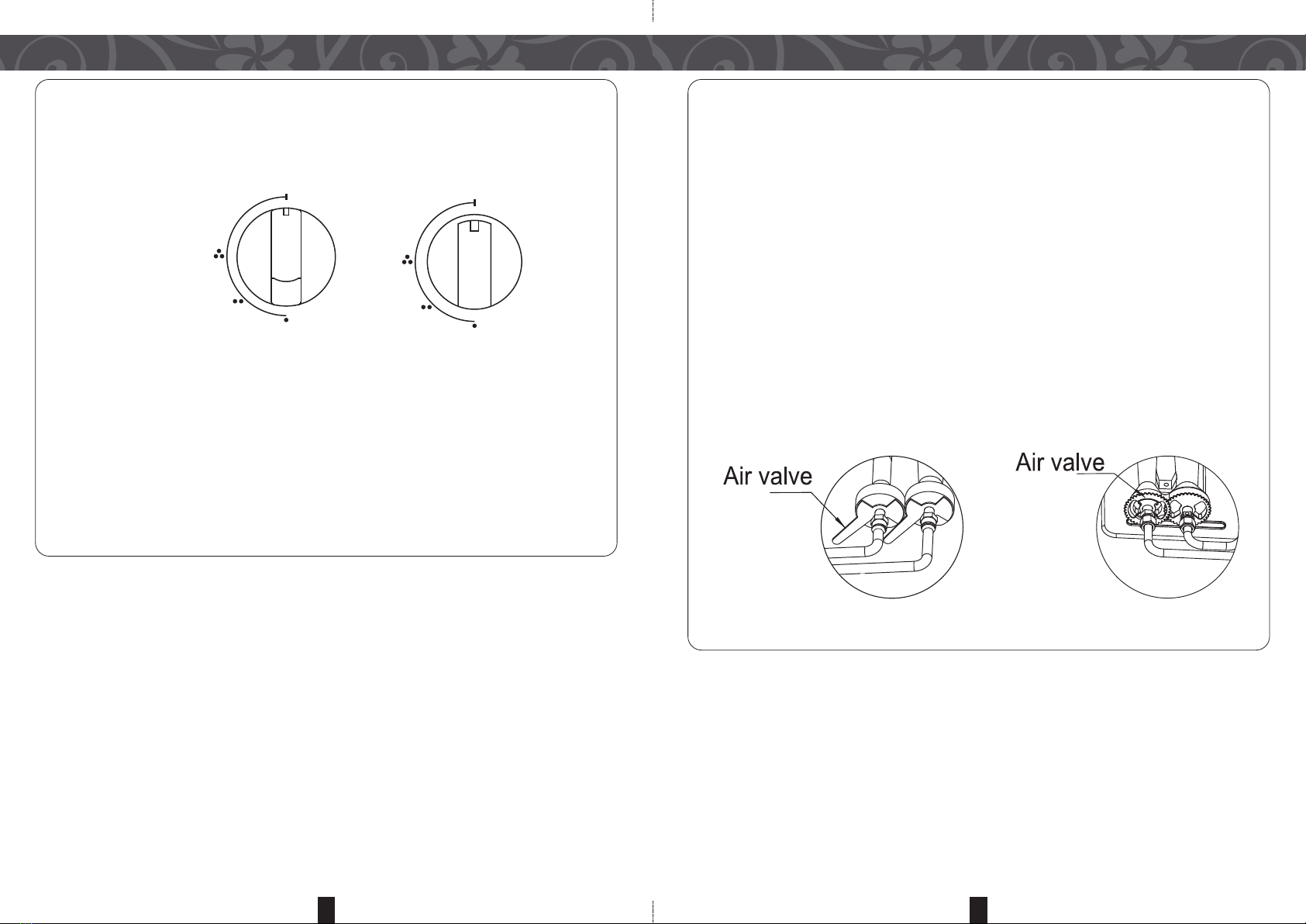
4. Clean the ends of the electronic ignition device (applicable for cooktops with ignition
device) carefully and frequently. Make sure the gas holes are not clogged.
5. While still warm, clean the hobs with a damp cloth and rub with a little oil.
6. Rinse stainless steel parts with water and dry well as these can be stained if it
remains in contact with highly calciferous water or detergents containing phosphorus.
7. It is recommended to clean up the spills object after every cook.
GREASING THE TAPS
This procedure can only be performed by an authorized service technician as taps may be
clogged over long period of use and may be difficult to turn.
CARE & CLEANING
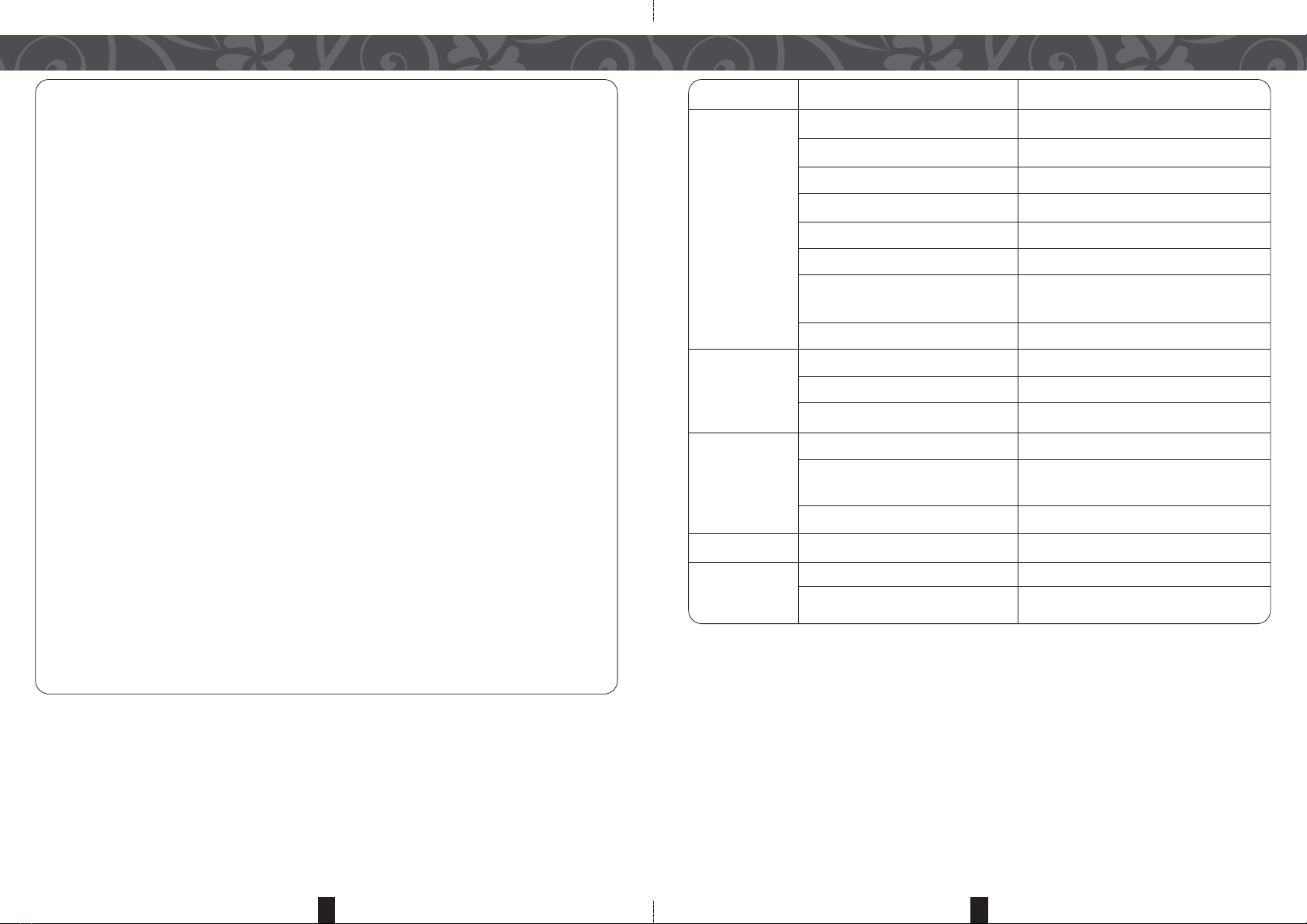
P OBLEM CAUSES SOLUTIONS
Failed Ignition Power is not connected. Connect ower.
High voltage wire leakage. Re lace high voltage wire.
Ignition orcelain head leakage. Re lace high voltage wire
Pulse ignitor is broken. Re lace ulse ignitor
Microswitch connection is faulty. Re lace/adjust microswitch.
Battery installation is faulty. Install battery correctly.
Incorrect distance between ignition Adjust to 5-6mm distance.
orcelain head and burner ca .
Gas su ly is not connected. Reconnect gas su ly.
Flame Failure – Incorrect throttle osition. Adjust throttle osition
Device Open Incorrect thermocou le osition. Adjust thermocou le osition
Valve Time Failure
Flame failure device malfunction. Re lace flame failure device
Backfiring Im ro er burner ca osition. Adjust burner ca .
Burner leakage or throttle o ens too Re lace burner or adjust throttle.
wide.
Burner ca is u side down. Adjust burner ca .
Flameout Throttle o ens too wide. Adjust throttle.
Noise Incorrect burner ca osition. Adjust burner ca .
Throttle o ens too wide. Adjust throttle.

98
INSTALLATION INSTALLATION
The following instructions are intended for the installer. The manufacturer shall not be held
responsible for damages arising from procedures carried out by unauthorized persons
which may void the warranty.
IMPO TANT: Disconnect appliance from the power supply before performing any
maintenance or repairs.
1.This hob unit must be installed by a qualified technician to avoid hazard.
2.Please refer to the following installation die-cut template (figure 1) supply with your
unit when marking holes for mounting and installation.
HOB POSITIONING
IMPO TANT: This appliance may be installed and used only in permanent ventilated
areas. The following requirements must be observed.
• The area must be fitted with a ventilation system which vents smoke and gases from
combustion to the outside. This means installing a hood or electric ventilator that
automatically powers on when the hob is in use.
• The area must have an air flow for proper combustion. This must be 2m3/h per kW of
installed power.
• The airflow can be created using an enclosed vent with an inner cross section of at least
100cm2which must be free from obstructions.
• If the appliance does not have a flame failure device, the vent should preferably have an
internal cross section of 200cm2.
• Alternatively, the area should allow indirect venting through ventilation ducts as specified
above as long as the adjacent area does not pose a fire risk (bedroom/shared area).
• Intensive and prolonged use of the appliance may require additional ventilation such as
opening a window or increasing the power of the air intake system (if available).
INSTALLATION OF BUILT-IN HOBS
Check after opening the box
• Check the gas supply compliance and gas limit of the hob. Then check the integrity,
quantity and proper connection of all accessories.
Drill hole
• Drill a hole according to the installation plate or hole size drawing on the worktop of the
cabinet. eave at least 150mm below the hob bottom for gas supply connection.
Hob placement
• Place hob into the hole, ensuring it is stable inside the worktop.
Gas pipe connection
• The hob should be connected to the gas supply by an authorized installer, ensuring that
it complies to local rules and regulations.
ubber hose connection
• Use the ø9.5 gas connection hose to connect the hob to the gas supply. Ensure that the
rubber hose is inserted into the red line of the hob connector and secured using a pipe
clamp. Ensure hose is straight and not bent or twisted and away from high temperature.
Corrugated metal tube connection
• Use the corrugated metal tube gas connector (outside thread of gas connector is 1/2”)
to connect the hob to the gas supply tap. Use an adjustable screw nut and anti-
corrosion rubber ring seal in the middle to connect.
Incoming Gas Connector
C
Red Line
Pipe Clamp
Corrugated Metal Tube
Figure 1
695mm
398mm
R35mm

10
INSTALLATION
11
Leakage Test
• Once hob has been installed, ensure that all connections are properly sealed. Use
soapy water to spread on all connection areas and turn on the gas valve. Bubbles will
appear on areas which are not properly connected. Tighten the metal clamps and repeat
the above test until no more bubbles appear.
Electric power connection
• Use individual 10A socket with landing for the electric hobs.
Battery installation
• The battery box is located at the lower left side of the hob bottom. Install only Type D
batteries in the proper direction and replace it as and when required.
Burn test and finish
• It is recommended to conduct a burn test after installation for first use by an authorized
service personnel.
PARTS IDENTIFICATION & SPECIFICATIONS
6
3
2
1
7
8
9
5
4
10
11
PARTNAME
1.Pan Stand
2.Sparker
3.Outer Cap
4.Inner Cap
5.Decorative Cover
6.Anti-Spillage Tray
7.Knob
8.Glass Top
9.Heat Deflector
10. Energy Concentrator
11. Bottom Base
SPECIFICATIONS
Model MBH-825 Triblaze
Burner Head Double
Ignition System Continuity Spark
Consumption (kW) left right
5.5 (3+1 Rings) 5.5 (3+1 Rings)
Weight (Kg) 9
Gas iquid Petroleum Gas ( PG)
Pressure 28 MBAR
Rubber Hose Diameter Ø9.5mm
Top Plate Dimension (mm) 780( ) x 460(W)
Table of contents
Other Morgan Hob manuals