MORLEY-IAS MI-SC6 User manual

BEFORE INSTALLING
This information is included as a quick reference installation
guide. Refer to the appropriate control panel installation manual
for detailed system information. If the modules will be installed in
an existing operational system, inform the operator and local au-
thority that the system will be temporarily out of service. Discon-
nect the power to the control panel before installing the modules.
This system contains static sensitive components. Always ground
yourself with a proper wrist strap before handling any circuits so
that static charges are removed from the body. The housing cabi-
net should be metallic and suitably grounded.
NOTICE: This manual should be left with the owner/user of
this equipment.
GENERAL DESCRIPTION
The MI-SC6 Six Supervised Control Module is intended for use in
an intelligent alarm system. Each module is intended for switch-
ing applications involving DC which require wiring supervision.
A common SLC input is used for all modules. Each module has
its own address. A pair of rotary code switches is used to set the
address of the first module from 01 to 94. The remaining mod-
ules are automatically assigned to the next five higher addresses.
Provisions are included for disabling a maximum of three unused
modules to release the addresses to be used elsewhere. Each mod-
ule also has panel controlled green LED indicators. The panel can
cause the LEDs to blink, latch on, or latch off.
Each module has terminals for connection to an external supply
circuit for powering devices on its Monitored Output Circuit.
Each supply must be power limited and its voltage/current limits
must be at or below those specified in Table 1.
There is a short circuit protection monitor for each module. This
is provided to protect the external power supply against short cir-
cuit conditions on the Monitored Output Circuit.
M450-01-00 1 I56-2956-000
MI-SC6
Six Supervised Control Module
SPECIFICATIONS
Normal Operating Voltage: 15-32VDC
Stand-By Current: 2.25 mA
Alarm Current: 35 mA (assumes all six relays have been switched
once and all six LEDs solid on)
Temperature Range: -10°C to 55°C
Humidity: 10 to 93% Non-condensing
Dimensions: 17.3cm H x 14.7cm W x 3.2cm D
Accessories: Suitably grounded metallic cabinet
Wire Gauge: 0.9mm2 - 3.25mm2
Maximum Monitored Output Circuit
Wiring Resistance: 40 Ohms
by Honeywell
Morley IAS Fire Systems
Charles Avenue
Burgess Hill, West Sussex, RH15 9UF
Table 1:
INSTALLATION AND MAINTENANCE INSTRUCTIONS
I56-2956-000
CURRENT RATING MAXIMUM VOLTAGE LOAD DESCRIPTION APPLICATION
3A 30VDC Resistive Steady
2A 30VDC Resistive Pulsing
1A 30VDC Inductive (L/R = 2ms) Pulsing
.5A 30VDC Inductive (L/R = 2ms) Pulsing
Included:
Shipped on Board:
(1) Small shunt
(6) Large shunts on Enable Power Supply Monitors
(6) Large shunts on Disable Short Circuit Protection
(3) Large shunts on Sync Generator
NOTE: Three shunts on Sync Generator MUST NOT be removed.
COMPATIBILITY REQUIREMENTS
To ensure proper operation, this module shall be connected to a
listed compatible control panel.
The MI-SC6 Module shall be mounted in a suitably grounded
Metallic Cabinet for EMC compliance.
(7) 1 × 4 Terminal Blocks
(2) 32mm Stand offs
(15) Large Shunts
(4) Screws
(5) Short Power Supply Jumpers
(2) Small Shunts
(2) Nuts
(1) Long Power Supply Jumper
(2) EOL Relay
Connector Assembly
(6) 47k Ohm End of Line Resistor
C0905-00

NOTE: Monitored Output Circuit (M.O.C) refers to Notification
Appliance (NAC) on the PCB Legend.
NOTE: Place unused shunts on single pin to store on board for
future use.
NOTE: SLC wiring is the top terminal block, notification appli-
ance/power supply is the bottom for terminal T0.
WIRING NOTES
• All wiring must conform to applicable local code, ordinances
or regulations.
• For easier wiring, assign all power-limited wiring to one side of
the enclosure rather than alternating with non power-limited.
Monitored Output Circuit Wiring and Supervision
Typical applications (figures 2 and 3) connect the positive ter-
minal of the Monitored Output Circuit to the monitored output
circuit+ terminal and the negative device terminal to the adja-
cent monitored output circuit- terminal. Connect one (for each
monitored output circuit) of the supplied EOL resistors across the
monitored output circuit+ and monitored output circuit- wires, at
the ends farthest away from the monitored output circuit terminal
of the MI-SC6.
TABLE 2
Terminal NAC + NAC -
Base address T0 T0
Base address + 1 T1 T1
Base address + 2 T2 T2
Base address + 3 T3 T3
Base address + 4 T4 T4
Base address + 5 T5 T5
Table 2 shows terminal pin assignment to base addresses
Power Supply Wiring and Supervision
Table 3 gives an overview of how the power connectors, T0–T5
and T10–T15, are interconnected by the circuit board (PCB). The
external supply connection points, at T0–T5, are marked by PS–
and PS+ on the PCB legend. Pin 1 is indicated by a dot next to
T10–T16. The odd pins, on T10–T16, always connect to PS– pins
(e.g. PS–, of the +0 monitored output circuit, is connected to
T10–1 and T11–1). The even pins always connect to PS+ pins
(e.g. PS+, of the +5 monitored output circuit, is connected to
T15-4 and T16-2).
TABLE 3
-PS -PS PS+ PS+
T0 T10 pin 1 T10 pin 1 T10 pin 2 T10 pin 2
T1 T11 pin 3 T10 pin 1 T10 pin 4 T10 pin 2
T2 T12 pin 3 T10 pin 1 T10 pin 4 T10 pin 2
T3 T13 pin 3 T10 pin 1 T10 pin 4 T10 pin 2
T4 T14 pin 3 T10 pin 1 T10 pin 4 T10 pin 2
T5 T15 pin 3 T10 pin 1 T10 pin 4 T10 pin 2
All power supplies, external to the cabinet (in which the MI-SC6
is housed), should be connected to T0–T5 which are suitable con-
nectors for field wiring. The 1 x 4 terminal blocks, shown on page
1, should be used to make these connections.
All Monitored Output Circuits can be wired to be powered by
separate external supplies (figure 2 is typical), or a single supply
M450-01-00 2 I56-2956-000
WIRING
NOTE: All wiring must conform to applicable local codes, ordi-
nances, and regulations.
1. Install module wiring in accordance with the job drawings
and appropriate wiring diagrams.
2. All wiring to the MI-SC6 is done via terminal blocks. In order
to properly make electrical connections strip approximately 5
mm of insulation from the end of wire, sliding the bare end of
the wire under the clamping plate screw.
3. Set the address on the modules per the job drawing. Use the
rotary code switches to set the address of the first module
(between 01 and 94).
The remaining modules are automatically assigned to the next
five higher addresses. For example, if the base address switch is
set to 28, the next five modules will be addressed to 29, 30, 31,
32, and 33.
DO NOT set the lowest address above 94, as the other modules will
be assigned to nonexistent addresses.
4. A shunt is provided to disable a maximum of three unused
modules (see Figure 1). Modules are disabled from the high-
est address and work downward. If two modules are dis-
abled, the lowest four addresses will be functional, while the
highest two will be disabled. For example, if the shunt for Ad-
dress Disable is placed on “two” and the base address switch
is set to 28, the modules will be assigned to 28, 29, 30 and 31,
disabling the higher two positions.
5. There is a short circuit protection option for each address.
The board is shipped with short circuit protection disabled for
each address represented by six large shunts on the “Disable
Short Circuit Protection” area. To enable short circuit protec-
tion for an address, remove the corresponding shunts from
the “Disable Short Circuit Protection” area. When enabled,
the module will not switch power supply if a short circuit
condition exists on a Monitored Output Circuit.
NOTE: Short circuit protection may only be enabled if power sup-
ply monitoring is enabled.
NOTE: The synchronization feature is currently not supported.
Figure 1:
ENABLE POWER SUPPLY MONITOR
DISABLE SHORT CIRCUIT PROTECTION
SYNC GENERATOR
SIDE VIEW:
TOP VIEW:
SLC WIRING TERMINAL
NOTIFICATION APPLIANCE/
POWER SUPPLY TERMINAL
FOR FUTURE USE
A/B SELECT
DISABLE 1
DISABLE 2
DISABLE 3
6. There is a power supply monitor that must be enabled to fa-
cilitate short circuit protection (see Figure 1). The module is
shipped with power supply monitoring enabled represented
by six large shunts on the pins of the “Enable Power Supply
Monitor” area.
C0204-00

M450-01-00 3 I56-2956-000
(figure 3 is typical) can be shared among multiple monitored out-
put circuits. If a supply is to be shared, between Monitored Out-
put Circuits wired to a common PCB, use the short power supply
jumpers shown on page 1. The jumpers can be used on T11–T15.
Refer to Table 4 for jumper functions.
TABLE 4
JUMPER LOCATION
MONITORED OUTPUT CIRCUIT PAIR
SHARING SUPPLY
T11 +0 and +1
T12 +1 and +2
T13 +2 and +3
T14 +3 and +4
T15 +4 and +5
A supply can be wired to be shared among multiple PCBs in the
same cabinet (figure 4 is typical). To share among multiple PCBs:
use the long power supply jumpers (shown on page 1) to connect ei-
ther T10 or T16, of one PCB, to either T10 or T16 of the other PCB.
An EOL relay must be used for every external power supply (fig-
ures 2–3 are typical). The EOL relay coil should always be con-
nected at the external power supply input of the module which
is connected farthest away from the power supply. The EOL relay
contacts should always be connected in series with the Monitored
Output Circuit wiring of the same module. The EOL relay coil
should be connected across the PS+ (red wire) and PS- (black
wire) if it is connected at T0 – T5. The EOL relay coil should
be connected across adjacent pins (red – even pin#, black – odd
pin#), of the same connector, if T10 – T16 are used.
All cabling must comply with local standards or codes of practice.
All external power supplies must be voltage regulated with bat-
tery back-up.
BASE ADDRESS
STATUS
INDICATORS
NAC
PS
NAC
PS
—
+
+
—
NAC
PS
—
+
+
—
NAC
PS
—
+
+
—
NAC
TOP
BOT
– +
+ NAC –
– +
– PS +
SLC
PS
—
+
+
—
+1 +2 +3 +4 +5
T11
T10
T0
+0
T12
T1 T2 T3 T4 T5
T13 T14 T15
T16
ENABLE POWER SUPPLY MONITOR
DISABLE SHORT CIRCUIT PROTECTION
—
+
+
—
A/B SELECT
DISABLE 1
DISABLE 2
DISABLE 3
0
1
2
3
456789
0
1
2
3
456789
EXTERNAL
POWER
SUPPLY
TO NEXT
DEVICE
–
–
+
+
FROM PANEL OR
PREVIOUS DEVICE
–
+
–
+
COMMUNICATION LINE 32 VDC MAX.
SEE PANEL INSTRUCTION MANUAL
FOR WIRE REQUIREMENTS.
LPOWER-LIMITED
AND SUPERVISED TOP OF T0
+
–
(–)
(+) VIO VIO
(–)
(+)
47K
47K
BLK
BLK
RED
RED
Figure 3. Style Y Monitored Output Circuit configuration with a single supply shared by 2 Monitored
Output Circuits:
BASE ADDRESS
STATUS
INDICATORS
NAC
PS
NAC
PS
—
+
+
—
NAC
PS
—
+
+
—
NAC
PS
—
+
+
—
NAC
TOP
BOT
– +
+ NAC –
– +
– PS +
SLC
PS
—
+
+
—
+1 +2 +3 +4 +5
T11
T10
T0
+0
T12
T1 T2 T3 T4 T5
T13 T14 T15
T16
ENABLE POWER SUPPLY MONITOR
DISABLE SHORT CIRCUIT PROTECTION
—
+
+
—
A/B SELECT
DISABLE 1
DISABLE 2
DISABLE 3
0
1
2
3
456789
0
1
2
3
456789
EXTERNAL
POWER
SUPPLY
TO NEXT
DEVICE
–
–
+
+
FROM PANEL OR
PREVIOUS DEVICE
–
+
–
+
–
+
–
+
COMMUNICATION LINE 32 VDC MAX.
SEE PANEL INSTRUCTION MANUAL
FOR WIRE REQUIREMENTS.
POWER-LIMITED
AND SUPERVISED TOP OF T0
+
–
(–)
(+) VIO VIO
(–)
(+)
(–)
(+)
(–)
(+)
47K
47K
BLK
RED
*NOTE 1: EOL Relay Coil Connections must be
made using EOL Relay Connector Assembles on
T10-T16 in event that all monitored Output Circuits
on the PCB have dedicated supplies.
Figure 2. Example of Class B, Style Y Monitored Output Circuit configuration with a single supply dedicated
to a single Monitored Output Circuit:
C0200-01
C0201-00

M450-01-00 4 I56-2956-000
Figure 4. Example of multiple boards sharing same external supply:
BASE ADDRESS
NAC
PS
NAC
PS
—
+
+
—
NAC
PS
—
+
+
—
NAC
PS
—
+
+
—
NAC
TOP
BOT
– +
+ NAC –
– +
– PS +
SLC
PS
—
+
+
—
+1 +2 +3 +4 +5
A
A
T11
T10
T0
+0
T12
T1 T2 T3 T4 T5
T13 T14 T15
T16
ENABLE POWER SUPPLY MONITOR
DISABLE SHORT CIRCUIT PROTECTION
—
+
+
—
A/B SELECT
DISABLE 1
DISABLE 2
DISABLE 3
0
1
2
3
456789
0
1
2
3
456789
BASE ADDRESS
NAC
PS
NAC
PS
—
+
+
—
NAC
PS
—
+
+
—
NAC
PS
—
+
+
—
NAC
TOP
BOT
– +
+ NAC –
– +
– PS +
SLC
PS
—
+
+
—
+1 +2 +3 +4 +5
T11
T10
T0
+0
T12
T1 T2 T3 T4 T5
T13 T14 T15
T16
ENABLE POWER SUPPLY MONITOR
DISABLE SHORT CIRCUIT PROTECTION
—
+
+
—
A/B SELECT
DISABLE 1
DISABLE 2
DISABLE 3
0
1
2
3
456789
0
1
2
3
456789
EXTERNAL
POWER
SUPPLY
+–
PCB 1 PCB 2
VIEW A-A
C0203-00
NOTE: Supply is shared by Monitored Output Circuits +0 and +1 (on PCB 1) as well as +3, +4, and +5 (on PCB 2). Refer to figure
3 for typical Monitored Output Circuit wiring. Make certain lip on long power supply jumper engages retaining tab on T10 or T16 as
shown in View A-A:

Ogni circuito di alimentazione deve essere dotato di un limitatore
della potenza e i limiti di tensione/corrente devono essere pari o
inferiori a quelli specificati nella Tabella 1.
Ogni modulo è dotato di un monitor per la protezione da
corto circuiti. Questo monitor ha la funzione di proteggere
l’alimentazione esterna da situazioni di corto circuito sul Cir-
cuito D’uscita Supervisionato.
Accessori in dotazione:
(7) Morsettiera 1 × 4
(2) Stand offs da 32mm
(15) Blocchi di
dervazione grandi
(4) Viti
(5) Jumper di alimentazione (2) Derivazione
piccole Jumper
di alimentazione
(2) Dadi
(1) Jumper di alimentazione lungo
(2) Gruppo connettore
del relé di fine linea
(6) Resistori di fine
linea da47k Ohm
Elementi a bordo scheda:
(1) Derivazioni piccole jumper di alimentazione
(6) Derivazioni grandi in posizione abilita monitor di alimentazione
(6) Derivazioni grandi in posizione disabilita protezione da corto circuito
(3) Derivazioni grandi in posizione Generatore DI SINCRONISMO
NOTA: Le tre derivazioni in posizione Generatore DI SIN-
CRONISMO NON DEVONO essere rimosse.
PRIMA DELL’INSTALLAZIONE
Le informazioni qui riportate fungono da guida all’installazione di
consultazione rapida. Per informazioni più dettagliate sul sistema,
consultare l’apposito manuale di installazione del pannello di con-
trollo. In caso di installazione dei moduli in un sistema operativo
già funzionante, informare l’operatore e le autorità locali che il
sistema rimarrà temporaneamente fuori servizio. Prima di instal-
lare i moduli, scollegare l’alimentazione del pannello di controllo.
Il sistema contiene componenti sensibili elettricità statica. Prima
di maneggiare qualsiasi tipo di circuito, collegarsi sempre a massa
utilizzando un’apposita fascia da polso che respinge le cariche
statiche dal corpo. È importante che la struttura del cabinet sia
metallica e adeguatamente collegata a massa.
AVVISO: Il presente manuale deve essere consegnato al propri-
etario/all’utente di questo apparecchio.
DESCRIZIONE GENERALE
Il modulo di controllo con sei sistemi di supervisione MI-SC6 è
stato progettato per l’uso in sistemi d’allarme intelligenti. Ogni
modulo è destinato ad applicazioni di switching tra cui CA, CC
o applicazioni audio, che richiedono una upervisione del cablag-
gio. Per tutti i moduli viene utilizzato un ingresso SLC tradizio-
nale. Ogni modulo possiede un proprio indirizzo. Per impostare
l’indirizzo del primo modulo su un valore compreso tra 01 e 94,
utilizzare la coppia di switch con codice a rotazione. Ai restanti
moduli vengono assegnati automaticamente i cinque successivi
indirizzi più alti. La disabilitazione di un massimo di tre moduli
non utilizzati è regolata da particolari disposizioni che consen-
tono di riutilizzare altrove questi indirizzi. Ogni modulo dispone
anche di indicatori LED di colore verde controllati dal pannello. È
importante che a seconda delle istruzioni del pannello, i LED pos-
sono lampeggiare, essere attivati oppure disattivati.
Ogni modulo dispone di morsetti per la connessione ad un cir-
cuito di alimentazione esterno per dispositivi di alimentazione sul
Circuito D’uscita Supervisionato.
M450-01-00 5 I56-2956-000
MI-SC6
Modulo di controllo a sei canali
SPECIFICHE
Normale tensione di esercizio: 15 - 32 VDC
Corrente in stand-by: 2.25 mA
Corrente di allarme: 35 mA (a condizione che tutti i sei relè siano stati attivati una volta e
che tutti i sei LED siano accesi in modo fisso)
Range di temperatura: da -10°C a 55°C
Umidità: dal 10 all’93% senza formazione di condensa
Dimensioni: A 173 mm x L 147 mm x P 25 mm
Accessori: Cabinet metallico dotato di un’adeguata messa a terra
Sezione conduttori: 0.9 mm² - 3.25 mm²
Massima resistenza del cablaggio
del circuito Circuito d’uscita Supervisionato: 40 ohm
Morley IAS Fire Systems
Via Grandi 22
S. Donato Milanese, Milano, Italia
ISTRUZIONI DI INSTALLAZIONE E MANUTENZIONE
POTENZA NOMINALE CORRENTE TENSIONE MASSIMA DESCRIZIONE DEL CARICO APPLICAZIONE
3A 30 VDC Resistivo continuo
2A 30 VDC Resistivo impulsivo
1A 30 VDC Induttivo (L/R = 2 ms) impulsivo
.5A 30 VDC Induttivo (L/R = 5 ms) impulsivo
Tabella 1:
by Honeywell
C0905-00

Figure 1:
ABILITA MONITOR DI ALIMENTAZIONE
DISABILITA PROTEZIONE DA CORTO
CIRCUITO
GENERATORE SINCRONIZZATO
VISTA LATERALE:
VISTA DALL'ALTO:
MORSETTIERA DI CABLAGGIO SLC
DISPOSITIVO DI NOTIFICA/
MORSETTIERA DI ALIMENTAZIONE
PER USO FUTURO
SELEZIONE A/B
DISABILITA
1
DISABILITA
2
DISABILITA
3
6. Vi è tuttavia un monitor di alimentazione che deve essere abil-
itato per agevolare la protezione da corto circuito (ved. figura
7). Il modulo viene fornito con la funzione di monitoraggio
dell’alimentazione abilitata come indicato da sei grandi de-
rivazioni sui pin dell’area “Abilita monitor di alimentazione”.
NOTA: Circuito D’uscita Supervisionato (M.O.C.), si riferisce alla
Notification Appliance (N.A.C.) sulla legenda del circuito stampato.
NOTA: Posizionare le derivazioni inutilizzate su un singolo pin in
modo che possano essere conservate per usi futuri.
NOTA: il terminali SLC sono locati sulla morsettiera in posizione
sopraelevata.
Note sul Cablaggio
• L’intero cablaggio deve essere conforme a tutte le normative,
ordinanze e disposizioni locali vigenti.
• Per un cablaggio più semplice, disporre l’intero cablaggio con
limitazione della potenza su un lato dell’apparecchio anziché
alternarlo con dispositivi senza limitazione della potenza.
Supervisione e cablaggio Circuito D’uscita Supervisionato
Vedi applicazioni tipiche nelle figure 2 e 3: collegare il morsetto
positivo del/i dispositivo/i di notifica al morsetto Circuito D’uscita
Supervisionato + e il morsetto negativo al morsetto Circuito
D’uscita Supervisionato - adiacente. Collegare uno ( per ciascun
Circuito D’uscita Supervisionato ) dei resistori di fine linea forniti
ai fili Circuito D’uscita Supervisionato + e Circuito D’uscita Super-
visionato -, in corrispondenza delle estremità più distanti rispetto
al morsetto Circuito D’uscita Supervisionato del modulo MI-SC6.
TABELLA 2
Terminale NAC + NAC -
Indirizzo Base T0 T0
Indirizzo Base + 1 T1 T1
Indirizzo Base + 2 T2 T2
Indirizzo Base + 3 T3 T3
Indirizzo Base + 4 T4 T4
Indirizzo Base + 5 T5 T5
TABELLA 2 mostra l’assegnazione dei terminali con riferi-
mento all’indirizzo base
M450-01-00 6 I56-2956-000
REQUISITI DI COMPATIBILITÀ
Per garantire il corretto funzionamento, collegare questo modulo
al pannello di controllo di un sistema compatibile elencato. Il
modulo MI-SC6 deve essere montato all’interno di un contenitore
metallico collegato a massa per incontrare i requisiti di compati-
bilità elettromagnetica.
CABLAGGIO
NOTA: L’intero cablaggio deve essere conforme a tutte le norma-
tive, ordinanze e disposizioni locali vigenti.
1. Installare il cablaggio del modulo conformemente ai dia-
grammi di lavoro e ai relativi schemi di cablaggio.
2. L’intero cablaggio del MI-SC6 passa attraverso delle morset-
tiere. Per eseguire in modo corretto le connessioni elettriche
rimuovere circa 5mm di materiale isolante dall’estremità del
filo e far passare l’estremità scoperta del filo sotto la piastra di
fissaggio e serrarne la vite.
3. Impostare l’indirizzo dei moduli secondo il diagramma di
lavoro. Per impostare l’indirizzo del primo modulo (valore com-
preso tra 01 e 94) utilizzare gli switch con codice a rotazione.
Ai restanti moduli vengono automaticamente assegnati i cinque
successivi indirizzi più alti. Se ad esempio l’indirizzo dello switch
di riferimento è impostato su 28, ai cinque moduli successivi ver-
ranno assegnati gli indirizzi 29, 30, 31, 32 e 33.
Non impostare l’indirizzo più basso su un valore superiore a 94,
poiché agli altri moduli verrebbero assegnati indirizzi inesistenti.
4. È disponibile una derivazione che consente di disabilitare un
massimo di tre moduli non utilizzati (ved. figura 7). I moduli
vengono disabilitati a partire da quello con l’indirizzo più
alto. Se vengono disabilitati due moduli, i quattro moduli con
l’indirizzo più basso rimarranno funzionanti mentre i due
con l’indirizzo più alto verranno disabilitati. Se ad esempio
la derivazione per la disabilitazione dell’indirizzo si trova su
“due” e l’indirizzo dello switch di riferimento è impostato su
28, ai Moduli verranno assegnati gli indirizzi 28, 29, 30 e 31,
mentre le due posizioni più alte verranno disabilitate.
5. Ogni indirizzo prevede un’opzione per la protezione da corto
circuito. È importante che ricordare Ogni scheda viene fornita
con la protezione da corto circuito disabilitata per tutti gli
indirizzi indicata da sei grandi derivazioni in posizione “Dis-
abilita protezione da corto circuito”. Per abilitare la protezi-
one da corto circuito di un indirizzo, rimuovere le derivazioni
corrispondenti dalla posizione “Disabilita protezione da corto
circuito”. Quando questa funzione è abilitata, il modulo non
attiverà l’alimentazione in caso di una condizione di corto
circuito rilevata dal. Circuito D’uscita Supervisionato
NOTA: La protezione da corto circuito può essere abilitata solo se
è stato abilitato il monitoraggio dell’alimentazione.
NOTA: La funzione di sincronizzazione non è attualmente supportata.
C0277-00

M450-01-00 7 I56-2956-000
Supervisione e cablaggio di alimentazione
La tabella 3 offre una panoramica di come i connettori di alimen-
tazione T0-T5 e T10-T15 sono interconnessi dalla scheda di cir-
cuito (PCB). È importante che Nella legenda del PCB, i punti di
connessione con l’alimentazione esterna in corrispondenza dei
connettori T0-T5 sono contrassegnati da PS- e PS+. Il pin 1 è
indicato da un punto accanto a T10-T16. I pin dispari, su T10-T16,
sono sempre collegati ai PS- (ad es. il PS-, del Circuito D’uscita
Supervisionato +0, è collegato a T10-1 e a T11-1). È importante
che I pin pari sono invece sempre collegati ai pin PS+ (ad es. il
PS+, del Circuito D’uscita Supervisionato +5, è collegato a T15-4
e a T16-2)
TABELLA 3
-PS -PS PS+ PS+
T0 T10 pin 1 T10 pin 1 T10 pin 2 T10 pin 2
T1 T11 pin 3 T10 pin 1 T10 pin 4 T10 pin 2
T2 T12 pin 3 T10 pin 1 T10 pin 4 T10 pin 2
T3 T13 pin 3 T10 pin 1 T10 pin 4 T10 pin 2
T4 T14 pin 3 T10 pin 1 T10 pin 4 T10 pin 2
T5 T15 pin 3 T10 pin 1 T10 pin 4 T10 pin 2
Tutte gli alimentatori, esterni al cabinet (in cui si trova il modulo
MI-SC6) devono essere collegati al T0-T5 che sono connettori in-
dicati per il cablaggio di campo. Per eseguire questi collegamenti,
è necessario utilizzare le morsettiere 1 x 4, mostrate a pagina 1.
Tutti i Circuito D’uscita Supervisionato possono essere cablati in
modo da essere alimentati da alimentatori esterni (la figura 2 ne
è un esempio tipico) oppure più Circuito D’uscita Supervisionato
possono condividere un singolo limentatore (la figura 3 ne è un
esempio tipico). In caso di alimentazione condivisa tra Circuito
D’uscita Supervisionato collegati ad una scheda PCB comune,
utilizzare i jumper di alimentazione corti mostrati a pagina 1. I
jumper possono essere utilizzati su T11-T15. Per le funzioni dei
jumper ved.
TABELLA 4
Un alimentatore può essere cablato in modo da essere condiviso tra
più PCB nello stesso cabinet (la figura 4 ne è un esempio tipico).
POSIZIONE DEI
JUMPER
COPPIA DI Circuito D’uscita Supervisionato
CON ALIMENTAZIONE CONDIVISA
T11 +0 e +1
T12 +1 e +2
T13 +2 e +3
T14 +3 e +4
T15 +4 e +5
Per la condivisione tra più PCB: utilizzare i jumper di alimentazi-
one lunghi (ved. figura 1) per collegare il T10 o il T16 di una PCB
al T10 o al T16 dell’altra PCB.
È necessario utilizzare un relè di fine linea per ogni alimen-
tatore esterno (le figure 2-3 ne sono esempi tipici). È necessa-
rio collegare sempre la bobina del relè di fine linea all’ingresso
dell’alimentatore esterno del modulo che è collegato alle estremità
dei fili più distanti dall’ alimentatore. È necessario che i contatti
del relè di fine linea siano sempre collegati in serie con il cablaggio
Circuito D’uscita Supervisionato dello stesso modulo. La bobina
del relè di fine linea deve sempre essere collegata al PS+ (filo
rosso) e al PS- (filo nero) se è collegata a T0 - T5. La bobina del
relè di fine linea deve essere collegata a pin adiacenti (rosso - pin
pari#, nero - pin dispari #), dello stesso connettore a condizione
che vengano utilizzati T10 - T16.
NOTE SUL CABLAGGIO
• Tutte le fonti di alimentazione esterne devono essere dotate
di dispositvi di limitazione della potenza e di una batteria di
back-up
INDIRIZZO DI RIFERIMENTO
INDICATORI
DI STATO
NAC
PS
NAC
PS
—
+
+
—
NAC
PS
—
+
+
—
NAC
PS
—
+
+
—
NAC
TOP
BOT
– +
+ NAC –
– +
– PS +
SLC
PS
—
+
+
—
+1 +2 +3 +4 +5
T11
T10
T0
+0
T12
T1 T2 T3 T4 T5
T13 T14 T15
T16
ABILITA MONITOR DI ALIMENTAZIONE
DISABILITA PROTEZIONE DA CORTO
CIRCUITO
—
+
+
—
SELEZIONE A/B
DISABILITA
1
DISABILITA
2
DISABILITA
3
0
1
2
3
456789
0
1
2
3
456789
ALIMENTAZIONE
ESTERNA
AL DISPOSITIVO
SUCCESSIVO
–
–
+
+
DAL PANNELLO O DAL
DISPOSITIVO PRECEDENTE
–
+
–
+
LINEA DI COMUNICAZIONE MAX. 32 V CC
PER I REQUISITI DEL CABLAGGIO
VED. MANUALE D'ISTRUZIONI DEL PANNELLO.
LIMITAZIONE DELLA
POTENZA E SUPERVISIONE Top of T0
+
–
(–)
(+) VIO VIO
(–)
(+)
47K
47K
BLK
BLK
ROSSO
ROSSO
*NOTA 1: Le connessioni della bobina del
relè di fine linea devono essere effettuate
utilizzando gruppi di connessione per relè
di fine linea su T10-T16 nel caso in cui tutti
i Circuito D’uscita Supervisionato sulla PCB
abbiano alimentazioni dedicate.
Figura 2. Esempio di configurazione Circuito D’uscita Supervisionato Classe B, tipo Y con una singola alimen-
tazione dedicata ad un singolo Circuito D’uscita Supervisionato:
C0276-00

INDIRIZZO DI RIFERIMENTO
NAC
PS
NAC
PS
—
+
+
—
NAC
PS
—
+
+
—
NAC
PS
—
+
+
—
NAC
TOP
BOT
– +
+ NAC –
– +
– PS +
SLC
PS
—
+
+
—
+1 +2 +3 +4 +5
A
A
T11
T10
T0
+0
T12
T1 T2 T3 T4 T5
T13 T14 T15
T16
ABILITA MONITOR DI ALIMENTAZIONE
DISABILITA PROTEZIONE DA CORTO
CIRCUITO
—
+
+
—
SELEZIONE A/B
DISABILITA 1
DISABILITA 2
DISABILITA 3
0
1
2
3
456789
0
1
2
3
456789
INDIRIZZO DI RIFERIMENTO
NAC
PS
NAC
PS
—
+
+
—
NAC
PS
—
+
+
—
NAC
PS
—
+
+
—
NAC
TOP
BOT
– +
+ NAC –
– +
– PS +
SLC
PS
—
+
+
—
+1 +2 +3 +4 +5
T11
T10
T0
+0
T12
T1 T2 T3 T4 T5
T13 T14 T15
T16
ABILITA MONITOR DI ALIMENTAZIONE
DISABILITA PROTEZIONE DA CORTO
CIRCUITO
—
+
+
—
SELEZIONE A/B
DISABILITA 1
DISABILITA 2
DISABILITA 3
0
1
2
3
456789
0
1
2
3
456789
ALIMENTAZIONE
ESTERNA
+–
PCB 1 PCB 2
VISTA A-A
M450-01-00 8 I56-2956-000
Figura 4. Esempio di più schede che condividono la stessa alimentazione esterna:
C0270-00
Figura 3. Esempio di configurazione Circuito D’uscita Supervisionato Classe B, tipo Y con un singolo alimen-
tatore condiviso da 2 Circuito D’uscita Supervisionato:
INDIRIZZO DI RIFERIMENTO
INDICATORI
DI STATO
NAC
PS
NAC
PS
—
+
+
—
NAC
PS
—
+
+
—
NAC
PS
—
+
+
—
NAC
TOP
BOT
– +
+ NAC –
– +
– PS +
SLC
PS
—
+
+
—
+1 +2 +3 +4 +5
T11
T10
T0
+0
T12
T1 T2 T3 T4 T5
T13 T14 T15
T16
ABILITA MONITOR DI ALIMENTAZIONE
DISABILITA PROTEZIONE DA CORTO
CIRCUITO
—
+
+
—
SELEZIONE A/B
DISABILITA
1
DISABILITA
2
DISABILITA
3
0
1
2
3
456789
0
1
2
3
456789
ALIMENTAZIONE
ESTERNA
AL DISPOSITIVO
SUCCESSIVO
–
–
+
+
DAL PANNELLO O DAL
DISPOSITIVO PRECEDENTE
–
+
–
+
–
+
–
+
LINEA DI COMUNICAZIONE MAX. 32 V CC
PER I REQUISITI DEL CABLAGGIO
VED. MANUALE D'ISTRUZIONI DEL PANNELLO.
LIMITAZIONE DELLA
POTENZA E SUPERVISIONE Top of T0
+
–
(–)
(+)
VIO VIO
(–)
(+)
(–)
(+)
(–)
(+)
47K
47K
BLK
ROSSO
C0275-00
L’alimentazione è condivisa dai Circuito D’uscita Supervisionato (M.O.C.) +0 e +1 (sulla PCB 1) e da +3, +4 e +5 (sulla PCB 2). Per
informazioni sul cablaggio M.O.C. tipico, fare riferimento alle figure 9-12. Verificare che la piegatura del bordo sul jumper di alimentazi-
one lungo si agganci alla linguetta di fissaggio su T10 o T16 come mostrato nella vista A-A.

ANTES DE LA INSTALACIÓN
Esta información se utiliza como guía rápida para la instalación.
Consulte el manual de instalación correspondiente al panel de
control para obtener información detallada sobre el sistema. Si los
módulos se van a instalar en un sistema operativo ya existente,
informe al usuario y a la autoridad local de que dicho sistema es-
tará temporalmente fuera de servicio. Desconecte la alimentación
antes de instalar los módulos. Este sistema contiene componentes
sensibles a la electricidad estática. Utilice una pulsera de conexión
a tierra para manipular los circuitos de modo que se eliminen
las cargas estáticas. La carcasa del módulo también debe estar
conectada a tierra.
AVISO: Este manual debe permanecer al alcance del propietario/
usuario del equipo.
DESCRIPCIÓN GENERAL
El Módulo de Control MI-SC6 ha sido diseñado para su uso en un
sistema de alarma inteligente. Cada módulo sirve para conectar
aplicaciones que tengan corriente continua (DC) y que requieran
supervisión del cableado. Todos los módulos utilizan una entrada
de lazo SLC común. Cada módulo tiene su propia dirección. Para
configurar la dirección del primer módulo de 01 a 94 se utilizan
un par de selectores rotatorios. Al resto de los módulos se les
asignarán automáticamente las siguientes cinco direcciones nu-
méricas. Se incluye la posibilidad de desactivar un máximo de
tres módulos no utilizados, cuyas direcciones se pueden liberar y
utilizar en otro lugar.
Cada módulo dispone también de leds verdes controlados desde
el panel. Desde el panel se puede hacer que estos leds parpadeen,
se mantengan iluminados de forma fija o se apaguen.
Cada módulo dispone de terminales de conexión a un circuito
externo de alimentación, que alimenta equipos de su CIRCUITO
DE SALIDA SUPERVISADO. En cada módulo hay un monitor de
protección frente a cortocircuitos que sirve para proteger a la
fuente de alimentación externa de cortocircuitos en el CIRCUITO
DE SALIDA SUPERVISADO.
M450-01-00 9 I56-2956-000
MI-SC6
Módulo de control con 6 circuitos
de salida supervisada
ESPECIFICACIONES
Tensión de Funcionamiento Normal: 15-32VDC
Corriente en reposo: 2,25 mA
Corriente en Alarma: 35 mA (cuando los seis relés están activados y los seis LEDS están
iluminados de forma fija)
Intervalo de temperatura: de -10°C a 55°C
Humedad: de 10 a 93% No condensada
Dimensiones (mm): 173 (alto) x 147 (ancho) x 25 (fondo)
Accesorios: Cabina metálica conectada adecuadamente a tierra
Sección del Cable: 0,9 mm² - 3,25mm²
Máxima resistencia del CIRCUITO DE SALIDA SUPERVISADO: 40 Ohmios
Morley IAS Fire Systems
C/Ávila 25
San Sebastián de los Reyes, 28700 Madrid, Espana
Tabla 1:
INSTRUCCIONES DE INSTALACIÓN Y MANTENIMIENTO
CORRIENTE TENSIÓN MÁXIMA DESCRIPCIÓN DE LA CARGA APLICACIÓN
3A 30VDC Resistiva Fija
2A 30VDC Resistiva Intermitente
1A 30VDC Inductiva (L/R=2ms) Intermitente
0,5A 30VDC Inductiva (L/R=5ms) Intermitente
by Honeywell
Piezas incluidas:
(7) 1 × 4 Bloques
de terminales (2) Separadores
de 32mm
(15) Puentes grande
(4) Tornillos (5) Puentes de
alimentación cortos (2) Puentes
pequeños
(2) Tuercas
(1) Puente de alimentación largo
(2) Conector de Relé
de final de línea
(6) Resistencia de fin de
línea de 47k Ohmios
Elementos integrados:
(1) Puente pequeño
(6) Puentes grandes para Habilitar la Supervisión de Alimentación
(6) Puentes grandes para Anular Protección contra cortocircuitos
(3) Puentes grandes para Sincronización
NOTA: Los tres puentes de Sincronización NO DEBEN quitarse.
COMPATIBILIDAD
Para asegurar un funcionamiento adecuado, conecte este módulo
sólo a un panel de control compatible.
El MI-SC6 debe montarse en una cabina metálica conectada adec-
uadamente a tierra.
C0905-00

M450-01-00 10 I56-2956-000
CABLEADO
NOTA: Todos los cables deben ajustarse a los códigos, ordenanzas
y regulaciones locales.
1. Instale el cable del módulo según los dibujos y diagramas
correspondientes.
2. Todo el cableado del MI-SC6 se efectúa mediante bloques de
terminales. Efectúe las conexiones eléctricas pelando unos 5
mm del aislante del cable, a continuación, coloque el cable
pelado debajo del tornillo y enrosque el tornillo.
3. Ajuste la dirección en los módulos según el dibujo. Utilice los
selectores rotatorios para configurar la dirección del primer
módulo (entre 01 y 94).
Al resto de los módulos se les asignarán automáticamente las
cinco direcciones siguientes. Por ejemplo, si la dirección base se
ajusta con el número 28, a los otros cinco módulos se les adjudi-
carán las direcciones 29, 30, 31, 32 y 33.
NO debe configurar la dirección más baja por encima del número
94, ya que al resto de módulos se les adjudicarían direcciones que
no existen.
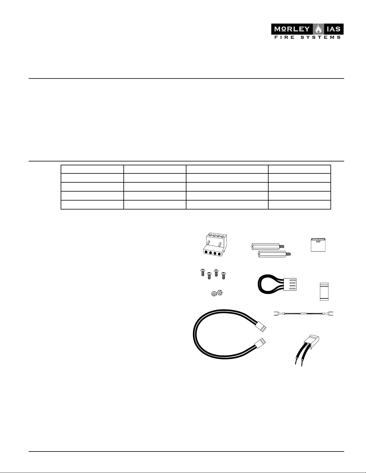
4. Se proporciona un puente para anular un máximo de dos
módulos no utilizados (ver Figura 7). Estos módulos se anu-
lan empezando por la dirección más alta. Si se anulan dos
módulos, estarán operativas las cuatro direcciones inferiores,
mientras que quedarán anuladas las dos más altas. Por ejem-
plo, si el puente de anular dirección se pone en “dos”, y la
dirección base se ajusta a 28, se adjudicarán a los módulos
los números 28, 29, 30 y 31 mientras que quedarán anuladas
las dos posiciones más altas (32, 33).
5. Existe una opción de protección contra cortocircuitos en cada
módulo. El módulo se envía con la protección contra corto-
circuitos anulada para cada dirección mediante los seis puen-
tes grandes colocados en la parte de la placa donde se indica
“anular protección cortocircuito” (Disable Short Circuit Pro-
tection). Para habilitar la protección contra cortocircuitos de
una dirección, retire el puente correspondiente. Una vez ha-
bilitada, el módulo no dejará pasar corriente eléctrica si existe
un cortocircuito en el CIRCUITO DE SALIDA SUPERVISADO.
NOTA: La protección contra cortocircuitos sólo se activará si está
habilitada la supervisión de alimentación.NOTA: La función de
sincronización no está habilitada actualmente.
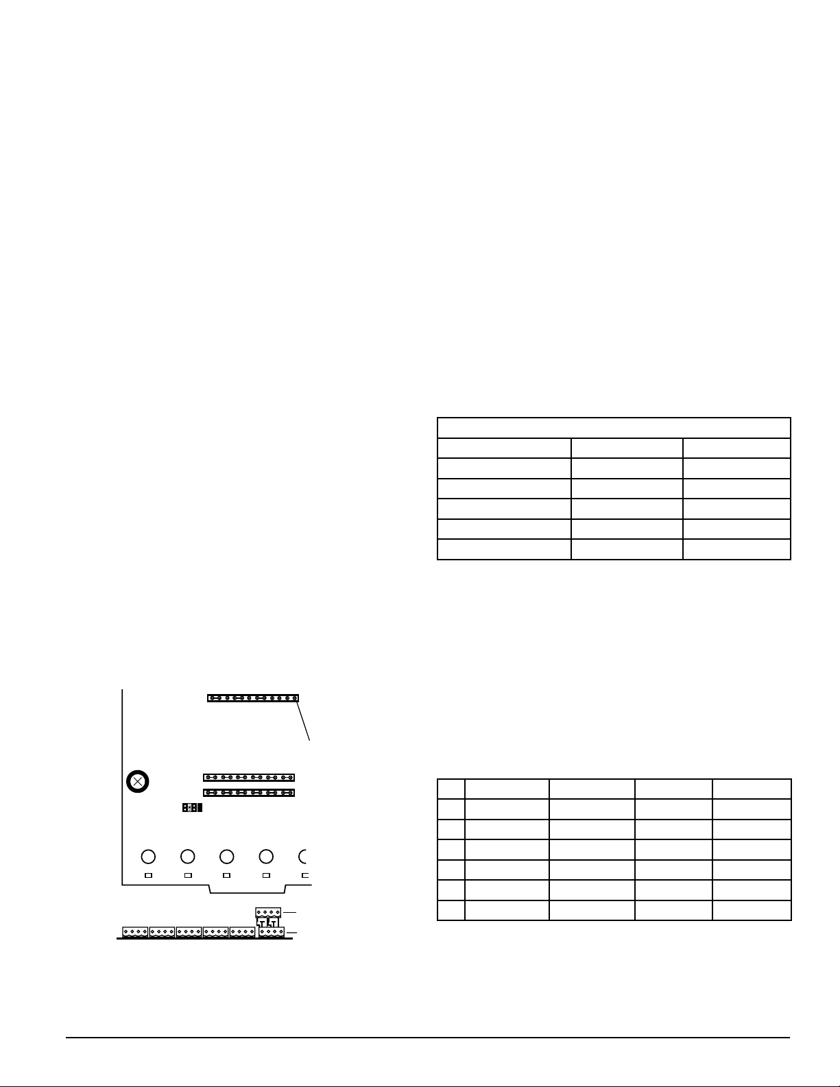
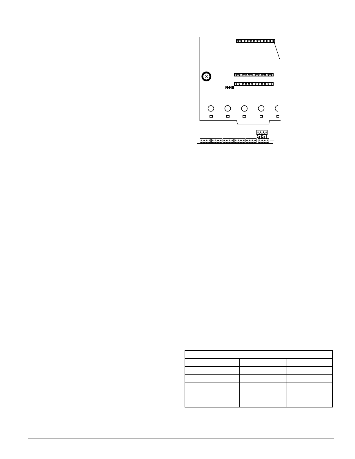
Figure 1:
HABILITAR SUPERVISIÓN
DE ALIMENTACIÓN
ANULAR PROTECCIÓN
CONTRA CORTOCIRCUITOS
SINCRONIZACIÓN
VISTA LATERAL:
VISTA SUPERIOR:
TERMINAL DE CABLEADO DE LAZO SLC
TERMINAL DE CIRCUITO DE
SEÑALIZACIÓN/ALIMENTACIÓN
PARA USO EN EL FUTURO
SELECCIÓN A/B
ANULAR 1
ANULAR 2
ANULAR 3
6. Se debe habilitar la supervisión de alimentación para facilitar
la protección contra cortocircuitos (ver Figura 7). El módulo in-
C0286-00
cluye una supervisión de alimentación habilitada por medio de
seis puentes grandes en los pins donde se indica “Habilitar su-
pervisión de alimentación” (Enable Power Supply Monitor).
NOTA: El CIRCUITO DE SALIDA SUPERVISADO (M.O.C.) viene
indicado como circuito de señalización (NAC) en la placa.
NOTA: Guarde los puentes no utilizados para un posible uso en
el futuro.
NOTA: El cableado de lazo SLC es el bloque de terminales supe-
rior, el circuito de señalización/alimentación es el inferior para el
terminal T0.
SOBRE EL CABLEADO
• Todo el cableado debe cumplir los códigos locales aplicables,
rdenanzas o regulaciones.
• Para facilitar el cableado, se deben colocar todos los cables
de potencia limitada en el mismo lado en lugar de colocarlos
alternados con los de potencia no limitada.
Supervisión y cableado del CIRCUITO DE SALIDA
SUPERVISADO.
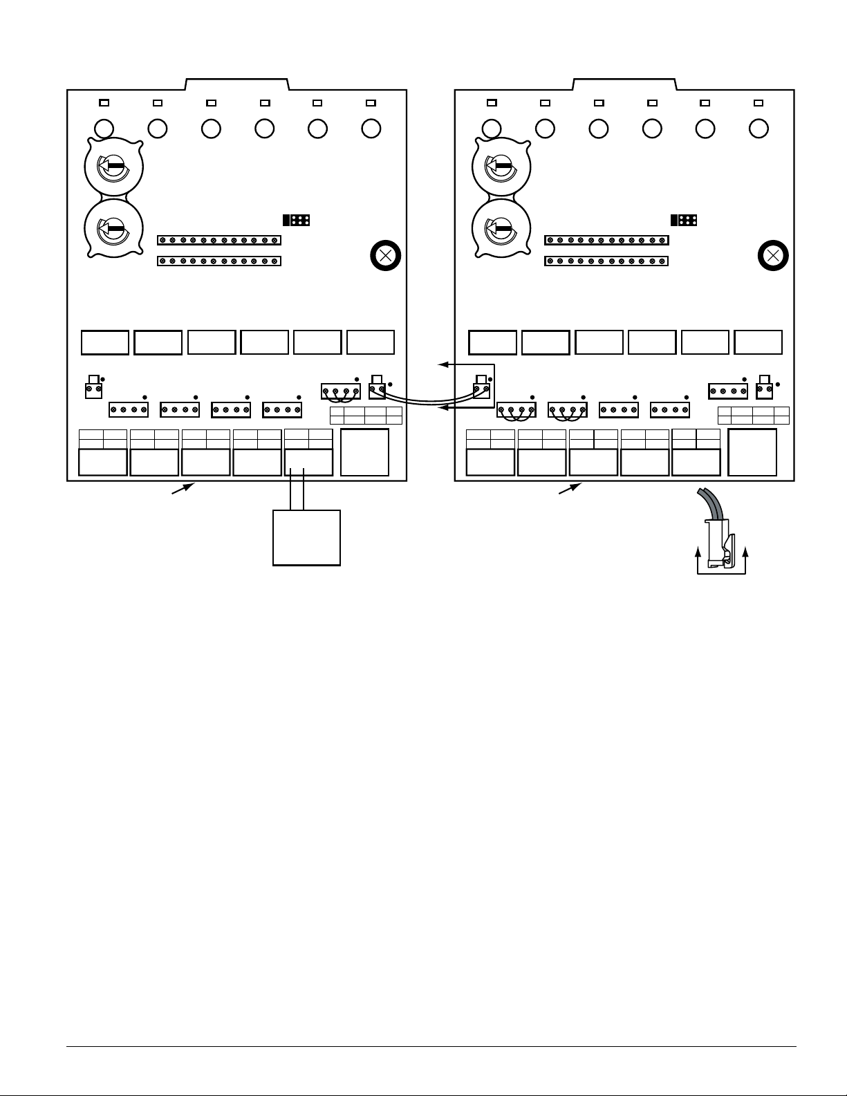
Para aplicaciones típicas, véase las figuras 2 y 3:
Conecte el terminal positivo del circuito o circuitos de salida su-
pervisado al terminal positivo del CIRCUITO DE SALIDA SUPER-
VISADO y el terminal negativo del equipo al terminal negativo del
CIRCUITO DE SALIDA SUPERVISADO adyacente. Conecte una (por
cada CIRCUITO DE SALIDA SUPERVISADO) de las resistencias de
final de línea en los dos cables positivo y negativo del CIRCUITO
DE SALIDA SUPERVISADO, en los extremos más alejados del ter-
minal del CIRCUITO DE SALIDA SUPERVISADO del MI-SC6.
TABLA 2
Terminal NAC + NAC -
Base address T0 T0
Base address + 1 T1 T1
Base address + 2 T2 T2
Base address + 3 T3 T3
Base address + 4 T4 T4
Base address + 5 T5 T5
Indica las asignaciones de los pins de los terminales a las di-
recciones de la base
Cableado de alimentación y supervisión
La Tabla 3 muestra cómo están interconectados los conectores de
alimentación T0–T5 y T10–T15, por medio de la placa (PCB). Los
puntos de conexión eléctrica externos, en T0–T5, están marcados
con PS– y PS+ en la placa PCB. El pin 1 está indicado con un punto
al lado de T10–T16. Los pins impares, en T10–T16, están siempre
conectados a pins PS– (ej. PS–, del +0 NAC, está conectado al
T10–1 y T11–1). Los pins pares siempre se conectan a los pins PS+
(ej. PS+, del +5 NAC, está conectado al T15-4 y T16-2). NOTA:
PS:Fuente de alimentación;NAC: Circuito de señalización.
TABLA 3
-PS -PS PS+ PS+
T0 T10 pin 1 T10 pin 1 T10 pin 2 T10 pin 2
T1 T11 pin 3 T10 pin 1 T10 pin 4 T10 pin 2
T2 T12 pin 3 T10 pin 1 T10 pin 4 T10 pin 2
T3 T13 pin 3 T10 pin 1 T10 pin 4 T10 pin 2
T4 T14 pin 3 T10 pin 1 T10 pin 4 T10 pin 2
T5 T15 pin 3 T10 pin 1 T10 pin 4 T10 pin 2

M450-01-00 11 I56-2956-000
Todas las fuentes de alimentación externas a la cabina que albergan
el MI-SC6 deben estar conectadas a T0–T5, que son los conectores
adecuados para el cableado. Para realizar estas conexiones deben
utilizarse los bloques de terminales 1 x 4 que se muestran en la
página 1.
Los CIRCUITOS DE SALIDA SUPERVISADOS se pueden conectar por
medio de fuentes externas individuales (las figuras 2 son un ejem-
plo), o varios circuitos de señalización pueden compartir una única
fuente de alimentación (las figuras 3 son un ejemplo). Si varios
CIRCUITOS DE SALIDA SUPERVISADOS conectados a una placa PCB
común deben compartir una única fuente de alimentación, utilice el
puente de alimentación corto que se muestra en página 1. Los puen-
tes pueden colocarse en T11–T15. Para ver las funciones del puente,
consulte la Tabla 4.
TABLA 4
UBICACIÓN DEL PUENTE
PAR DE CIRCUITOS DE
SALIDA SUPERVISADOS QUE
COMPARTEN SUMINISTRO
T11 +0 y +1
T12 +1 y +2
T13 +2 y +3
T14 +3 y +4
T15 +4 y +5
Se puede conectar una única fuente de alimentación de modo que
pueda ser compartida por varias placas PCB situadas en la misma
cabina (la figura 4 es un ejemplo). Para que se pueda compartir,
utilice el puente de alimentación largo (ver página 1) para conec-
tar el T10 o T16 de una placa al T10 o T16 de la otra placa.
Utilice un relé de final de línea para cada fuente de alimentación
externa (las figuras 2-3 son un ejemplo). La bobina del relé de
final de línea debe conectarse siempre a la entrada de la fuente
de alimentación externa del módulo conectado que está más lejos
de la fuente de alimentación. Los contactos de los relés de final
de línea deben estar siempre conectados en serie con el cable del
CIRCUITO DE SALIDA SUPERVISADO del mismo módulo. La bo-
bina del relé de final de línea debe estar conectada con el PS+
(cable rojo) y el PS-(cable negro) si está conectado al T0 – T5.
La bobina del relé de final de línea debe estar conectada en pins
adyacentes (rojo – pin número par, negro – pin número impar),
del mismo conector, si se utilizan los T10 – T16.
Todo el cableado debe cumplir los códigos de prácticas o normas
locales. Cualquier fuente de alimentación externa debe ser de ten-
sión limitada con batería de apoyo.
DIRECCIÓN BASE
INDICADORES
DE ESTADO
NAC
PS
NAC
PS
—
+
+
—
NAC
PS
—
+
+
—
NAC
PS
—
+
+
—
NAC
TOP
BOT
– +
+ NAC –
– +
– PS +
SLC
PS
—
+
+
—
+1 +2 +3 +4 +5
T11
T10
T0
+0
T12
T1 T2 T3 T4 T5
T13 T14 T15
T16
HABILITAR SUPERVISIÓN DE ALIMENTACIÓN
ANULAR PROTECCIÓN CONTRA
CORTOCIRCUITO
—
+
+
—
SELECCIÓN A/B
ANULAR 1
ANULAR 2
ANULAR 3
0
1
2
3
456789
0
1
2
3
456789
FUENTE DE
ALIMENTACIÓN
EXTERNA
AL DISPOSITIVO
SIGUIENTE
–
–
+
+
DESDE EL PANEL
O DISPOSITIVO ANTERIOR
–
+
–
+
LÍNEA DE COMUNICACIONES 32VDC MAX.
CONSULTAR MANUAL DE INSTRUCCIONES
DEL PANEL PARA REQUISITOS DE CABLEADO.
ALIMENTACIÓN LIMITADA
Y SUPERVISADA
PARATE SUPERIOR
DE T0
+
–
(–)
(+)
VIO VIO
(–)
(+)
47K
47K
NEGRO
NEGRO
ROJO
ROJO
*NOTA 1: las conexiones de la bobina del relé de
final de línea se deben realizar con conectores de
relé de final de línea en T10-T16 en caso de que
todos los circuitos de señalización en la placa dis-
pongan de alimentación dedicada.
Figura 2. Ejemplo de configuración del CIRCUITO DE SALIDA SUPERVISADO en Clase B, Estilo Y con una única
fuente de alimentación para un sólo CIRCUITO DE SALIDA SUPERVISADO:
C0280-00

M450-01-00 12 I56-2956-000
Figura 4. Ejemplo de varios tarjetas que comparten la misma fuente externa de alimentación:
DIRECCIÓN BASE
NAC
PS
NAC
PS
—
+
+
—
NAC
PS
—
+
+
—
NAC
PS
—
+
+
—
NAC
TOP
BOT
– +
+ NAC –
– +
– PS +
SLC
PS
—
+
+
—
+1 +2 +3 +4 +5
A
A
T11
T10
T0
+0
T12
T1 T2 T3 T4 T5
T13 T14 T15
T16
EHABILITAR SUPERVISIÓN DE ALIMENTACIÓN
ANULAR PROTECCIÓN CONTRA
CORTOCIRCUITO
—
+
+
—
SELECCIÓN A/B
ANULAR 1
ANULAR 2
ANULAR 3
0
1
2
3
456789
0
1
2
3
456789
DIRECCIÓN BASE
NAC
PS
NAC
PS
—
+
+
—
NAC
PS
—
+
+
—
NAC
PS
—
+
+
—
NAC
TOP
BOT
– +
+ NAC –
– +
– PS +
SLC
PS
—
+
+
—
+1 +2 +3 +4 +5
T11
T10
T0
+0
T12
T1 T2 T3 T4 T5
T13 T14 T15
T16
HABILITAR SUPERVISIÓN DE ALIMENTACIÓN
ANULAR PROTECCIÓN CONTRA
CORTOCIRCUITO
—
+
+
—
SELECCIÓN A/B
ANULAR 1
ANULAR 2
ANULAR 3
0
1
2
3
456789
0
1
2
3
456789
FUENTE DE
ALIMENTACIÓN
EXTERNA
+–
PCB 1 PCB 2
VISTA A-A
C0282-00
Figura 3. Ejemplo de configuración del CIRCUITO DE SALIDA SUPERVISADO en Clase B, Estilo Y con una única
fuente de alimentación compartida por dos circuitos de salida supervisados:
DIRECCIÓN BASE
INDICADORES
DE ESTADO
NAC
PS
NAC
PS
—
+
+
—
NAC
PS
—
+
+
—
NAC
PS
—
+
+
—
NAC
TOP
BOT
– +
+ NAC –
– +
– PS +
SLC
PS
—
+
+
—
+1 +2 +3 +4 +5
T11
T10
T0
+0
T12
T1 T2 T3 T4 T5
T13 T14 T15
T16
HABILITAR SUPERVISIÓN DE ALIMENTACIÓN
ANULAR PROTECCIÓN CONTRA
CORTOCIRCUITO
—
+
+
—
SELECCIÓN A/B
ANULAR 1
ANULAR 2
ANULAR 3
0
1
2
3
456789
0
1
2
3
456789
FUENTE DE
ALIMENTACIÓN
EXTERNA
AL DISPOSITIVO
SIGUIENTE
–
–
+
+
DESDE EL PANEL O
DISPOSITIVO ANTERIOR
–
+
–
+
–
+
–
+
LÍNEA DE COMUNICACIONES 32VDC MAX.
CONSULTAR MANUAL DE INSTRUCCIONES DEL
PANEL PARA REQUISITOS DE CABLEADO.
ALIMENTACIÓN LIMITADA
Y SUPERVISADA PARATE SUPERIOR DE T0
+
–
(–)
(+)
VIO VIO
(–)
(+)
(–)
(+)
(–)
(+)
47K
47K
NEGRO
ROJO
C0281-00
La alimentación la comparten los circuitos de salida supervisados +0 y +1 (de la PCB 1) así como los +3, +4 y +5 (de la PCB 2).
Consulte las figuras 3 para ver un ejemplo de cableado típico del CIRCUITO DE SALIDA SUPERVISADO. Asegúrese de que el conector
del puente de alimentación largo encaja correctamente en la pestaña de sujeción en T10 o T16, como se muestra en Vista A-A.

Im Lieferumfang enthalten:
Auf der Platine:
(1) Kleine Steckbrücken
(6) Lange Steckbrücken zur Einschaltung der Spannungsüberwachung
(6) Lange Steckbrücken zur Abschaltung der Kurzschlussüberwachung
(3) Lange Steckbrücken auf dem Anschluss Sync Generator
HINWEIS: Die drei Steckbrücken auf dem Sync Generator An-
schluss nicht entfernen .
STROMAUFNAHME MAX. SPANNUNG VERBRAUCHER APPLIKATION
3A 30VDC ohmsche Last nicht getaktet
2A 30VDC ohmsche Last Getaktet
1A 30VDC Induktiv (L/R = 2ms) Getaktet
0,5A 30VDC Induktiv (L/R = 5ms) Getaktet
VOR DER INSTALLATION
Diese Information dient als Kurzanleitung für die Installation.
Wenn Module in bereits betriebsbereite Anlagen eingebaut
werden, informieren Sie die zuständigen Personen und die regio-
nalen Behörden, dass ggfs. die Anlage zeitweise außer Betrieb
genommen wird. Schalten Sie die Zentrale vor dem Beginn der
Installationsarbeiten spannungsfrei. Das System beinhaltet Bau-
teile mit elektrostatischer Empfindlichkeit. Erden Sie sich vor dem
Umgang mit diesen Baugruppen mit einem geeigneten Erdungs-
band zur Ableitung der elektrostatischen Energie. Es sollten nur
Metallgehäuse mit geeigneter Erdung verwendet werden.
HINWEIS: Diese Anleitung sollte dem Betreiber ausgehändigt und
der Anlagendokumentation beigefügt werden.
ALLGEMEINES
Das MI-SC6 Relais-Steuermodul wird in intelligenten Gefahren-
meldeanlagen eingesetzt. Jedes Modul ist für das überwachte
Schalten von Wechsel- oder Gleichspannung sowie Audiosignalen
geeignet. Ein gemeinsamer Ringbus-Eingang wird für alle Module
verwendet. Mit den beiden Drehschaltern wird die Moduladresse
von 01 bis 94 eingestellt. Den verbleibenden Modulen werden au-
tomatisch immer die nächsten, um die Zahl 5 erhöhten, Adress-
nummern zugewiesen. Es besteht die Möglichkeit bis max. drei
nicht benötigte Module abzuschalten und deren Adressbereich für
andere Anwendungen freizugeben.
Jedes Modul hat eine, von der Zentrale gesteuerte, grüne LED-
Anzeige. Die Zentrale kann die LED blinkend, folgend ein oder
folgend aus ansteuern.
Jedes Modul verfügt über separate Anschlussklemmen zur einzel-
nen Spannungsversorgung der angeschlossenen Geräte an jedem
überwachten Steuerausgang. Jede Spannungsversorgung muss
strombegrenzt ausgelegt sein und den Spezifikationen für die
zulässigen Höchstwerte in Tabelle 1 entsprechen.
Jedes Modul verfügt über eine Kurzschlussüberwachung um die
externe Spannungsversorgung vor einem Kurzschluss auf dem
überwachten Steuerausgang zu schützen.
M450-01-00 13 I56-2956-000
MI-SC6
Überwachtes Sechs-Relais-Steuermodul
SPEZIFIKATION
Betriebsspannungsbereich: 15-32 VDC
Ruhestrom: 2,25 mA
Alarmstrom: 35 mA (bei 6 angesteuerten Relais und 6 dauerleuchtenden LED)
Temperaturbereich: -10 °C bis +55 °C
Luftfeuchte: 10 bis 93% ohne Betauung
Abmessungen: 173 x 147 x 32 (H x B x T in mm)
Maximale Anschluss Impedanz: 40 Ohm
Zubehör: geerdetes Metallgehäuse
Kabelquerschnitt: 0,9mm2 – 3,25mm²
Morley IAS
Berliner strasse 91
40880 Ratingen, Germany
Tabelle 1:
INSTALLATIONS- UND WARTUNGSANLEITUNG
by Honeywell
(7) 1 × 4 Anschlussklemmen
(2) 32mm Abstandshalter
(15) Große
Steckbrücken
(4) Metallschrauben (5) Kurze Steckverbinder
für Spannungsversorgung (2) Kleine
Steckbrücken
(2) Muttern
(1) Lange Steckverbinder
für Spannungsversorgung
(2) Abschluss-Relais
Baugruppe
(6) 47k Ohm Verbinder für
Abschlusswiderstand
C0905-00

Abbildung 1:
EINSCHALTUNG SPANNUNGSÜBERWACHUNG
ABSCHALTUNG KURZSCHLUSSÜBERWACHUNG
SYNC GENERATOR
SEITENANSICHT:
DRAUFSICHT:
RINGBUS-ANSCHLUSSKLEMMEN
ANSCHLUSSKLEMMEN
SPANNUNGSVERSORGUNG
AUSGANGSKREIS
ZUKÜNFTIGE FUNKTION
A/B AUSWAHL
ABSCHALTUNG 1
ABSCHALTUNG 2
ABSCHALTUNG 3
6. Die Überwachung der Spannungsversorgung muss einge-
schaltet sein um eine Kurzschlussüberwachung zu ermögli-
chen. (siehe Abbildung 1). Das Modul wird mit eingeschalteter
Spannungsüberwachung ausgeliefert, erkennbar an den sechs
großen Steckbrücken auf den Kontakten “Einschaltung der
Spannungsüberwachung”.
HINWEIS: „Einschaltung Spannungsuberwachung bezieht sich
auf „NOTIFICATION APPLIANCE“ auf der Platine”
HINWEIS: Stecken Sie nicht benutzte Steckbrücken zur Aufbe-
wahrung auf einen einzelnen Pin auf.
HINWEIS: Der Anschluss der Spannungsversorgung erfolgt an
den oberen, der Anschluss des überwachten Ausgangskreises an
den unteren Klemmen des Klemmenblocks T0
VERDRAHTUNGSHINWEISE
• Die Verdrahtung muss den nationalen Richtlinien entspre-
chen.
• Zur einfachen Installation sollte die Kabelführung von
strombegrenzten und nicht strombegrenzten Leitungen auf
der Baugruppe räumlich getrennt erfolgen
ÜBERWACHTER AUSGANG Verdrahtung und Überwachung
Typische Anwendungen siehe Abb. 2 und 3. Verbinden Sie die
positive Leitung des Ausgangskreises mit den + Ausgangsklem-
men des Moduls und die negative Leitung mit dem entsprechen-
den – Ausgangsklemmen des Moduls.
Schließen Sie jeweils einen der mitgelieferten Abschlusswider-
stände pro Ausgang am letzten Ausgangselement an.
TABELLE 2
Anschlüsse NAC + NAC -
Basis-Adresse T0 T0
Basis-Adresse + 1 T1 T1
Basis-Adresse + 2 T2 T2
Basis-Adresse + 3 T3 T3
Basis-Adresse + 4 T4 T4
Basis-Adresse + 5 T5 T5
Zeigt die Zuordnung der Anschlüsse zur Basis-Adresse
M450-01-00 14 I56-2956-000
KOMPATIBILITÄT
Für den ordnungsgemäßen Betrieb muss das Modul an eine gee-
ignete und kompatible Brandmelderzentrale angeschlossen werden.
Das MI-SC6-Modul sollte für die Erfüllung der EMV-Richtlinie in
einem geeigneten, geerdeten Metallgehäuse montiert werden
VERDRAHTUNG
HINWEIS: Die Verdrahtung muss gemäß den regionalen Aufla-
gen, Richtlinien und Anforderungen ausgeführt werden.
1. Installieren Sie das Module gemäß den Projektierungszeich-
nungen und den entsprechenden Anschlussdiagrammen.
2. Die Verdrahtung des MI-SC6 erfolgt über Schraubklemmen.
Entfernen Sie die Isolierung des Kabelendes auf ca. 5 mm
Länge und schieben Sie das abisolierte blanke Kabelende un-
ter die Klemmplatte der Schraubklemme und ziehen diese
fest an.
3. Stellen Sie die Moduladresse des ersten Modules (zwischen
01 und 94) gemäß ihren Projektierungsplänen mit den
Drehschaltern ein.
Die verbleibenden Module werden automatisch den nächsten
5 Adressen zugeordnet. Z.B.: Wenn die Startadresse auf 28 ein-
gestellt ist, belegen die anderen 5 Module die Adressen 29 – 33.
Stellen Sie niemals eine Erstadresse über 94 ein, weil dann die
nächsten Module als nicht vorhanden interpretiert werden.
4. Die mitgelieferten Steckbrücken ermöglichen die Abschaltung
von max. drei nicht benutzten Modulen (siehe Abbildung 1).
Module werden von der höchsten Adresse aus absteigend ab-
geschaltet. Wenn zwei Module abgeschaltet werden bleiben
die unteren vier Adressen aktiv und die beiden höchsten
Adressen werden deaktiviert. Wird die Steckbrücke zur Ad-
ressabschaltung z.B. in Position “Zwei” gesteckt und eine Er-
stadresse von 28 eingestellt, so werden die anderen Adressen
28, 29, 30 und 31 zugeordnet, während die beiden höchsten
Adressen abgeschaltet werden.
5. Für jede Adresse ist eine Kurzschlussüberwachung möglich.
Werkseitigwirddie Platinemitabgeschalteter Kurzschlussüber-
wachung ausgeliefert, erkennbar an den sechs langen
Steckbrücken in Position “Abschaltung der Kurzschlussüber-
wachung”. Um die Kurzschlussüberwachung für eine Adresse
einzuschalten entfernen Sie die entsprechende Steckbrücke.
Im eingeschalteten Zustand wird bei einem Kurzschluss auf
dem zugehörigen Steuerausgang, keine Versorgungsspannung
auf diesen überwachten Ansteuerkreis geschaltet.
HINWEIS: Die Kurzschlussüberwachung sollte nur eingeschaltet
werden, wenn auch die zugehörige Überwachung der externen
Spannungsversorgung eingeschaltet ist.
HINWEIS: Die Funktionalität „Synchronisieren“ wird zur Zeit
nicht unterstützt.
C0298-00

M450-01-00 15 I56-2956-000
TABELLE 3
-PS -PS PS+ PS+
T0 T10 pin 1 T10 pin 1 T10 pin 2 T10 pin 2
T1 T11 pin 3 T10 pin 1 T10 pin 4 T10 pin 2
T2 T12 pin 3 T10 pin 1 T10 pin 4 T10 pin 2
T3 T13 pin 3 T10 pin 1 T10 pin 4 T10 pin 2
T4 T14 pin 3 T10 pin 1 T10 pin 4 T10 pin 2
T5 T15 pin 3 T10 pin 1 T10 pin 4 T10 pin 2
Alle externen Versorgungsspannungen (außerhalb des MI-SC6
Montagegehäuses) sollten an die Anschlüsse T0-T5 angeschlos-
sen werden, die auch für den Anschluss der Ausgangsleitungen
vorgesehen sind. Der 4-fach Klemmenblock, siehe Seite 1, sollte
für diesen Anschluss genutzt werden.
Alle überwachten Ausgangskreise können mit einer eigenen ex-
ternen Spannungsversorgung angeschlossen s. Abb. 2 oder mit
einer gemeinsamen Spannungsversorgung für mehrere überwa-
chte Ausgangskreise angeschlossen werden . s. Abb. 3 Wenn die
überwachten Ausgangskreise einer Platine mit einer gemeinsa-
men Spannung versorgt werden sollen, kann das kurze Steckka-
bel (siehe Seite 1) genutzt werden. Die Steckkabel können für die
Anschlüsse T11–T15 eingesetzt werden. Die Tabelle 4 zeigt die
Funktionen des Steckkabels.
TABELLE 4
Die Versorgungsspannung für mehrere Module in einem Gehäuse
kann mit einem Kabel weiterverbunden werden
( typische Darstellung in Abbildung 4 ). Um mehrere Platinen zu
verbinden verwenden Sie das lange Steckerkabel für die Span-
nungsversorgung (siehe erste Seite) und schließen es an T10 oder
T16 einer Platine an und verbinden es mit T10 oder T16 der näch-
sten Platine.
Für jede externe Spannungsversorgung muss ein Abschlussrelais
(EOL = End Of Line) eingesetzt werden (typische Darstellung
siehe Abb. 2–3 ). Die Spule des EOL-Relais wird immer an den
Spannungseingang des Modules angeschlossen, das am weitesten
von der Spannungsquelle entfernt ist.
Die Relaiskontakte werden in Serie mit den Kontakten auf dem
überwachten Ausgangskreis des Moduls geschaltet. Die EOL Re-
laisspule sollte für den Anschluss an T0-T5 an den PS+ (roter
Draht) und PS- (schwarzer Draht) angeschlossen werden. Beim
Anschluss der Relaisspule an T10-T16 sollten die benachbarten
Anschlüsse (rot – gerade Pin Nr. und schwarz – ungerade Pin Nr.)
einer Anschlussleiste verwendet werden.
*Hinweis 1: Die Spule des Abschlussrelais muss zur
eindeutigen Zuordnung der Spannungsversorgung
für alle Steuerausgänge auf den entsprechenden An-
schlüssen T10–T16 angeschlossen sein.
MODUL ADRESSE
ZUSTANDSANZEIGEN
NAC
PS
NAC
PS
—
+
+
—
NAC
PS
—
+
+
—
NAC
PS
—
+
+
—
NAC
OBEN
UNTEN
– +
+ NAC –
– +
– PS +
SLC
PS
—
+
+
—
+1 +2 +3 +4 +5
T11
T10
T0
+0
T12
T1 T2 T3 T4 T5
T13 T14 T15
T16
EINSCHALTUNG SPANNUNGSÜBERWACHUNG
ABSCHALTUNG KURZSCHLUSSÜBERWACHUNG
—
+
+
—
A/B AUSWAHL
ABSCHALTUNG 1
ABSCHALTUNG 2
ABSCHALTUNG 3
0
1
2
3
456789
0
1
2
3
456789
EXTERNE
SPANNUNGSVERSORGUNG
ZUR NÄCHSTEN
BAUGRUPPE
–
–
+
+
VON DER ZENTRALE ODER
VORHERIGER BAUGRUPPE
–
+
–
+
SIGNALLEITUNG 32 VDC MAX.
VERDRAHTUNGSANFORDERUNGEN
FÜR DIE STROMBEGRENZUNG UND
ÜBERWACHUNG SIEHE INSTALLTIONSANLEITUNG
DER ZENTRALE
STROMBEGRENZT
UND ÜBERWACHT OBEN VON T0
+
–
(–)
(+) VIOLETT VIOLETT
(–)
(+)
47K
47K
SCHWARZ
SCHWARZ
ROT
ROT
Abbildung 2. Beispiel für Betriebsart B:. Konfiguration der überwachten Steuerausgänge mit einer einzigen
Spannungsversorgung für einen einzelnen überwachten Steuerausgang:
JUMPER STELLUNG Überwachter Ausgangskreis
Spannungsversorgung, paarweise
T11 +0 and +1
T12 +1 and +2
T13 +2 and +3
T14 +3 and +4
T15 +4 and +5
C0299-00

M450-01-00 16 ©2006 System Sensor I56-2956-000
Abbildung 4. Beispiel zur gemeinsamen Spannungsversorgung von Modulen:
MODUL ADRESSE
NAC
PS
NAC
PS
—
+
+
—
NAC
PS
—
+
+
—
NAC
PS
—
+
+
—
NAC
PS
—
+
+
—
+1 +2 +3 +4 +5
A
A
T11
T10
T0
+0
T12
T1 T2 T3 T4 T5
T13 T14 T15
T16
EINSCHALTUNG SPANNUNGSÜBERWACHUNG
ABSCHALTUNG KURZSCHLUSSÜBERWACHUNG
—
+
+
—
A/B AUSWAHL
ABSCHALTUNG 1
ABSCHALTUNG 2
ABSCHALTUNG 3
0
1
2
3
456789
0
1
2
3
456789
MODUL ADRESSE
NAC
PS
NAC
PS
—
+
+
—
NAC
PS
—
+
+
—
NAC
PS
—
+
+
—
NAC
PS
—
+
+
—
OBEN
UNTEN
– +
+ NAC –
– +
– PS +
SLCOBEN
UNTEN
– +
+ NAC –
– +
– PS +
SLC
+1 +2 +3 +4 +5
T11
T10
T0
+0
T12
T1 T2 T3 T4 T5
T13 T14 T15
T16
EINSCHALTUNG SPANNUNGSÜBERWACHUNG
ABSCHALTUNG KURZSCHLUSSÜBERWACHUNG
—
+
+
—
A/B AUSWAHL
ABSCHALTUNG 1
ABSCHALTUNG 2
ABSCHALTUNG 3
0
1
2
3
456789
0
1
2
3
456789
EXTERNE
SPANNUNGSVERSORGUNG
+–
PCB 1 PCB 2
Darstellung A-A
Abbildung 3. Konfiguration der überwachten Steuerausgänge mit einer einzigen Spannungsversorgung für 2 Überwachte
Steuerausgänge:
MODUL ADRESSE
ZUSTANDSANZEIGEN
NAC
PS
NAC
PS
—
+
+
—
NAC
PS
—
+
+
—
NAC
PS
—
+
+
—
NAC
OBEN
UNTEN
– +
+ NAC –
– +
– PS +
SLC
PS
—
+
+
—
+1 +2 +3 +4 +5
T11
T10
T0
+0
T12
T1 T2 T3 T4 T5
T13 T14 T15
T16
EINSCHALTUNG SPANNUNGSÜBERWACHUNG
ABSCHALTUNG KURZSCHLUSSÜBERWACHUNG
—
+
+
—
A/B AUSWAHL
ABSCHALTUNG 1
ABSCHALTUNG 2
ABSCHALTUNG 3
0
1
2
3
456789
0
1
2
3
456789
EXTERNE
SPANNUNGSVER-
SORGUNG
ZUR NÄCHSTEN
BAUGRUPPE
–
–
+
+
VON DER ZENTRALE ODER
VORHERIGER BAUGRUPPE
–
+
–
+
–
+
–
+
SIGNALLEITUNG 32 VDC MAX.
VERDRAHTUNGSANFORDERUNGEN FÜR DIE STROMBEGRENZUNG
UND ÜBERWACHUNG SIEHE INSTALLTIONSANLEITUNG
DER ZENTRALE
STROMBEGRENZT
UND ÜBERWACHT OBEN VON T0
+
–
(–)
(+) VIO VIO
(–)
(+)
(–)
(+)
(–)
(+)
47K
47K
SCHWARZ
ROT
C0300-00
C0301-00
Die Versorgungsspannung wird auch zur Versorgung der überwachten Steuerausgänge +0 and +1 (auf Platine 1) sowie +3, +4, and
+5 (auf Platine 2) genutzt. Die Abbildungen 3 zeigen die typische Verdrahtung der Ausgangskreise. Vergewissern Sie sich dass der
Stecker des Spannungskabel, wie in der Darstellung A-A gezeigt, fest in den Halteclip von T10 oder T16 einrastet.
Table of contents
Languages:
Other MORLEY-IAS Fire Alarm manuals
Popular Fire Alarm manuals by other brands

GST
GST GST-MNA2C Installation and operation manual

Autronica
Autronica BS-200 How to operate

Vigilant
Vigilant MX1 installation guide

Harrington Signal
Harrington Signal Network Plus 21 Guide

Fire-Lite Alarms
Fire-Lite Alarms MS-9200 Programming, installation, maintenance and operating instruction manual

Zeta
Zeta INFINITY ID2 User manual, maintenance guide & log book