Page 6 Controller Installation Guide
MEL-TEM-011 ISSUE 1
Communications
Presently, three types of serial interface are available for controllers, RS485, RS232 and
current loop. The RS485 interface is a full duplex, multi-drop topology consisting of two
differential pairs, transmit and receive, carried on standard Belden twisted pair cable. The
communications cable is daisy chained from the master controller (generally a PC based
RS485) to each controller. The cable must not be spurred or starred as this can cause
transmission problems. Each pair must be terminated at each end of the line with a quarter watt
150 ohm resistor. For connection details of the RS485 card, see the attached connection
diagram.
A standard RS232 interface is available with 9 pin delta connector termination and is suitable
for connection to line drivers, modems and direct connection to a personal computer. The
current loop interface is available which is fully compatible with Tunstall/Tann equipment.
This network topology is the same as RS485 but requires no termination resistors and can cover
greater distances. Both the current loop and RS485 cards have LED's to indicate reception of
data from the main controller. The RS485 card has both transmit and receive indicators, these
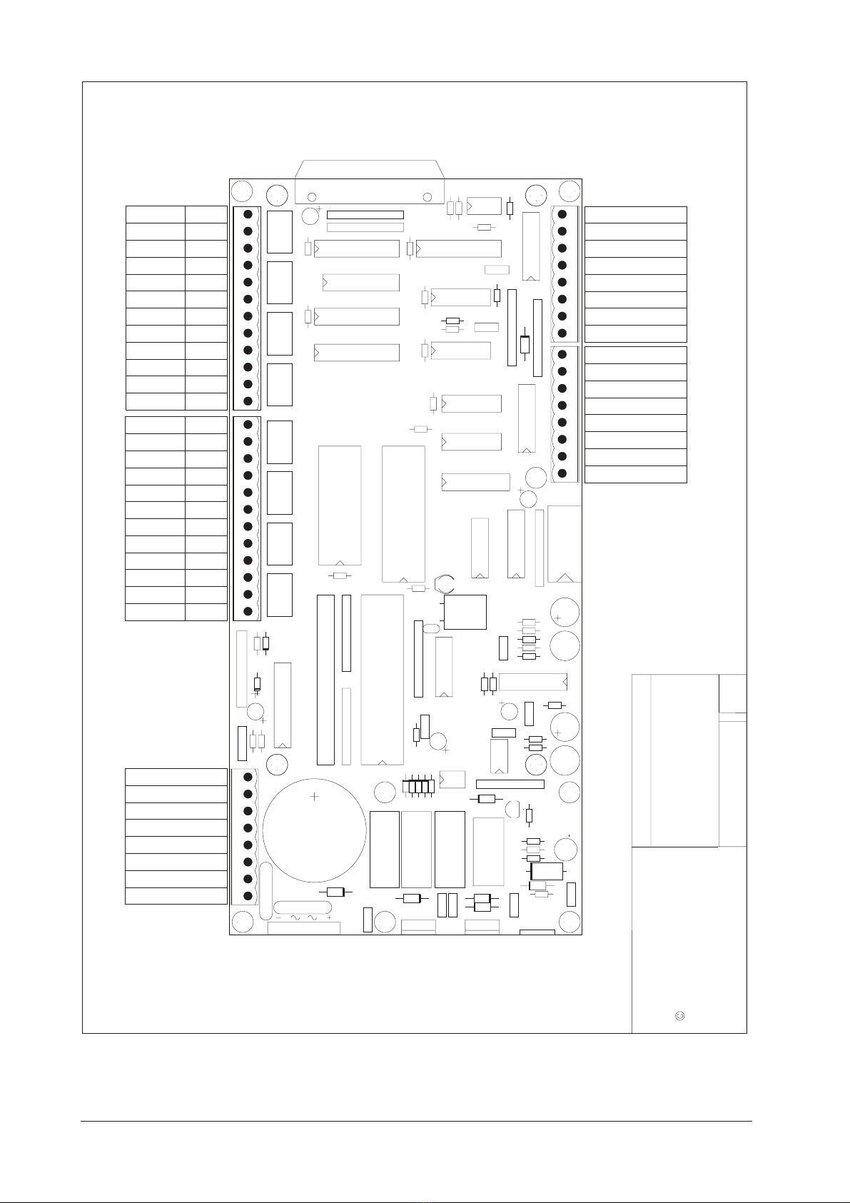
are provided for diagnostic purposes. All of the interfaces plug into the main controller PCB
via an eight pin header and are secured using four M3 screws. When fitting communications
cards, ensure that the pins are correctly positioned in the socket before the controller has power
applied to it.
Installation considerations
When carrying out any wiring or maintenance on the controller, remove mains power and if
present, disconnect the battery. The plugable connectors are provided for ease of installation
and maintenance and are not 'hot insertable' (REMOVE THE POWER!). When inserting
plugs, ensure that they are positioned correctly as it is possible to insert a plug in an offset
position, eg. pin 1 in pin 2 position. Always ensure that there are no loose wires or foreign
objects in the enclosure which could short out the circuitry. Before a controller leaves the
factory it is tested for electrical safety. This test includes an earth bonding test. If any earth
bounds are removed by the installer, the equipment must be re-tested.
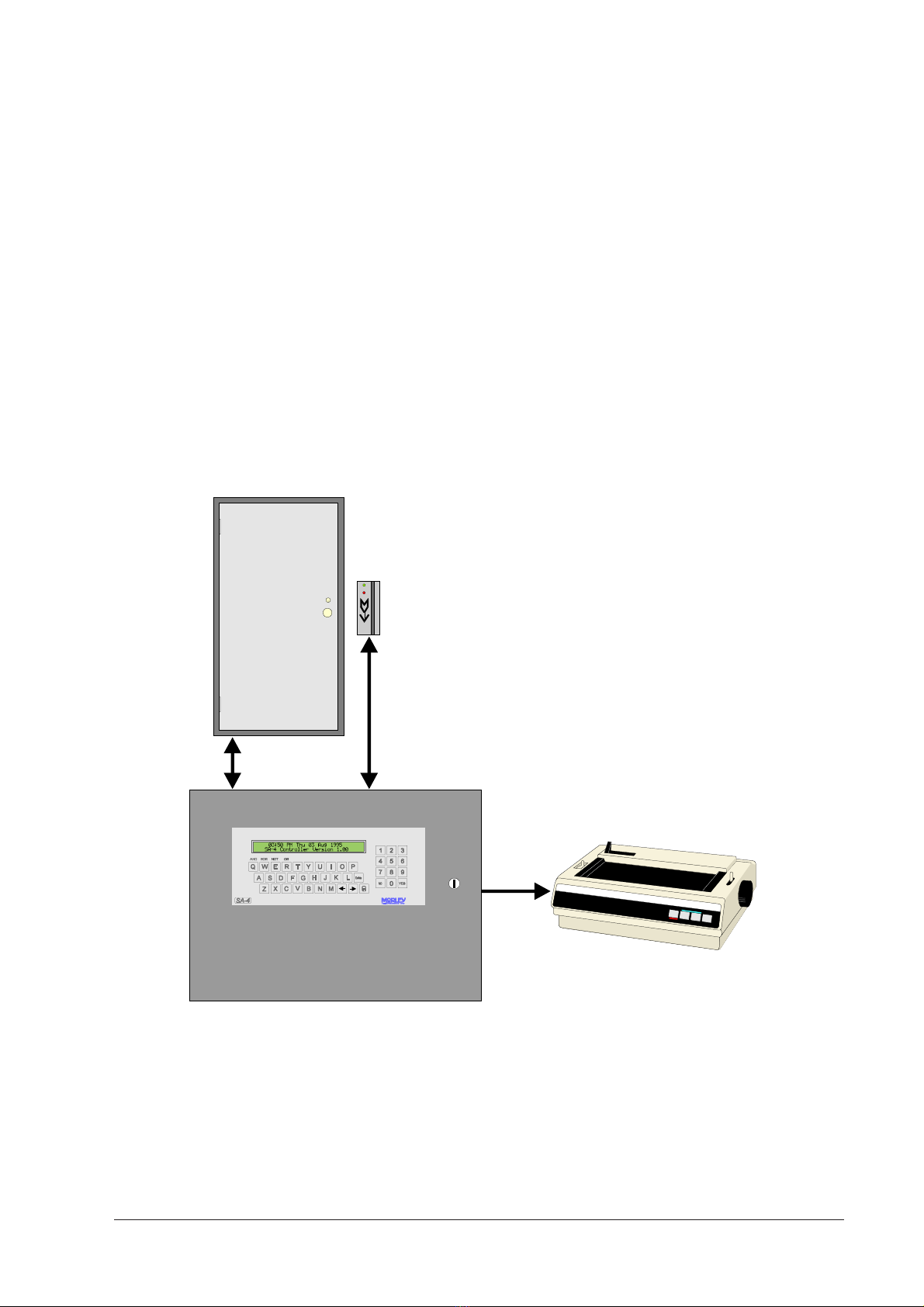
When positioning the controller, locate a position which is central to installed and potential
reader sites. This will minimise reader cable lengths. When mounting the controller on the wall,
ensure that the height chosen allows the controller to be programmed comfortably by the user.
DO NOT
Exceed 100m cable length between reader and controller.
Use unshielded cable.
Use cores from a reader cable to drive inductive loads (Door strikes).
Drive inductive loads without installing suitable suppresion devices.