Morra MH 530 User manual


2
1. Components of the crate:
There will also be a bag of parts.
Guards
Tines
Pto shaft
Gearbox cover
Support
Outer wheels
Jack
Jack stand
cylinders
Right arm
Left arm
Tongue
Central unit

3
2. Loosen top 3 bolts each side of the central gear box with an 8mm
hex key wrench. Then mount gear box cover with the front bolt
only, allowing the cover to pivot.
Note-sometimes if welds are too large attaching the arms to the
gear box you may have to grind the edges of the cover for it to fit
properly.
3.Remove the 2 bolts from rotor housing on each side and pivot the gear
box cover forward so that support can be installed with the bolt holes
in the cover aligned on top. Put the 2 bolts back in the flange that
goes over the rotor housing.
There are three
b
olt holes on this
flange. In this
step, only
replace front bolt
so that it can
p
ivot forward in
next step. Then
replace other two
bolts

4
4. Put the 2 bolts back in the flange that goes over the rotor housing.
Install 2 bolts and washer in the rear and top that secures the support
to gear box cover using a 19 mm socket (top holes are bolt and nut-
bottom threads into cover)
*At this point you will need to go back and tighten all bolts in the
assembly thus far as well as inserting the other two bolts
into the gear box cover
5. Using a 24 mm socket, attach the tongue to the support with the two
8.8 x 80 mm bolts( one on each side) Do not tighten the nuts tightly –
you want to allow the tongue to pivot on the bolts.
6. Attach the jack stand to the tongue with the cotter key provided in
the bag of parts. It is a good idea to grease the jack before
installing it.
Top of gear
box cover
Support

5
7. Attach the leveling jack to the tongue by first removing the
bracket, then inserting the eye in the jack foot over the stud. The
jack attaches to the housing by aligning a stud on the jack housing &
securing the jack bracket with a 17 mm socket
*Caution-when assembling arms-use the jack to keep the weight on
the unit shifted forward to the jackstand to prevent the unit from
flipping backwards.
8. Remove the rubber pads with a 13mm socket on each side before
attaching the arms to the central unit. Take out the 2 grease able
bolts that are in the yokes with a 35 mm socket
Make sure to remove all paint with emory cloth before attaching the
arms & be sure that the grease holes are not clogged. It is a good
idea to blow them out with an air gun.
Bracket
Mounting stud

6
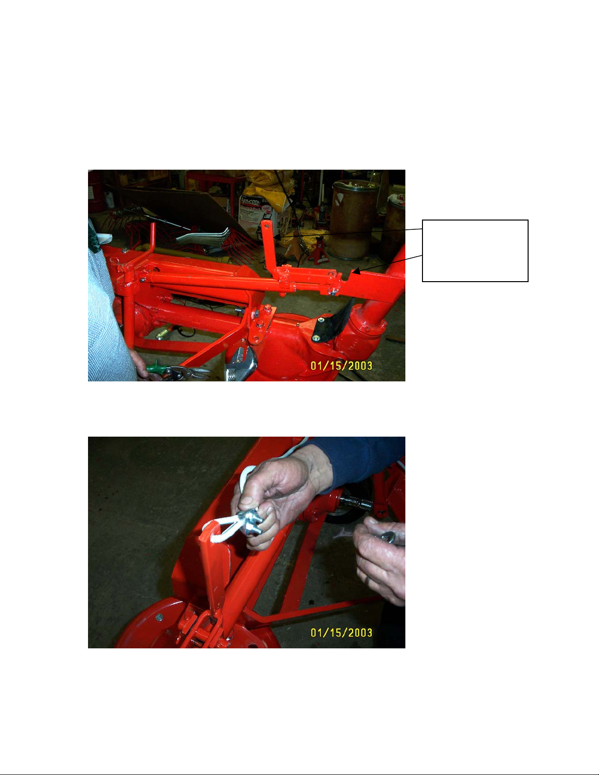
9. Install the dust covers and outer tire & wheels onto the spindles
the outer arms. The bearings in these wheels are sealed but it is still
is a good idea to put grease in the dust cap. Align the wheel in the
travel position.
There is a left and a right arm. They are easy to recognize by the
position of the bracket for the hydraulic cylinder mount.
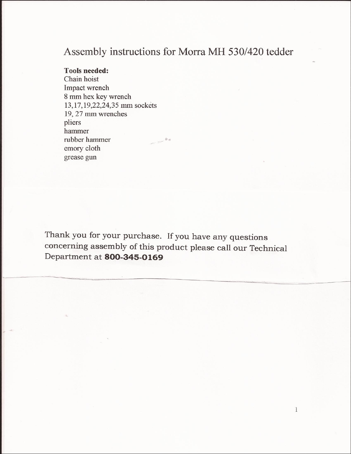
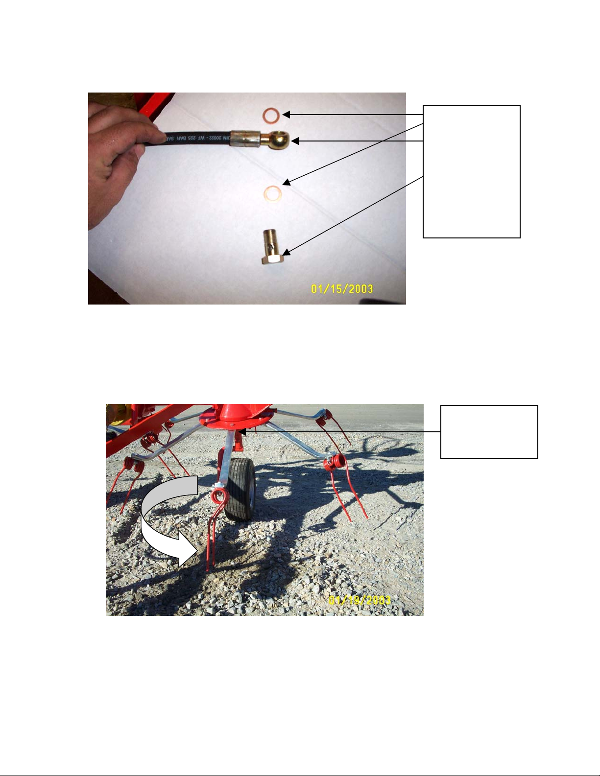
10. To attach the arm to the central unit, turn the rotor on the
central unit until the keyway on the shaft is at 12:00 and install the
keyway provided. It is also important to be sure there is no paint on
the shaft. You will also need to buff the paint from the yokes (inside
of central unit, outside of the arm)so that there is no problem with
fitting.
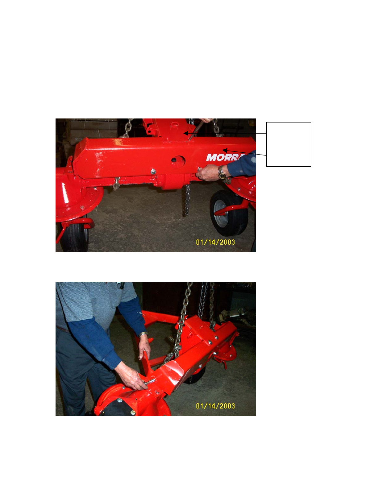
*This is also a good time to grease the universal joints on the arm.
Before installing the arm to the central unit, with the keyway at 12:00
and the arm yoke in line, you will want to notice the “timing” of the
unit to be sure that the inner and outer rake teeth will not collide.
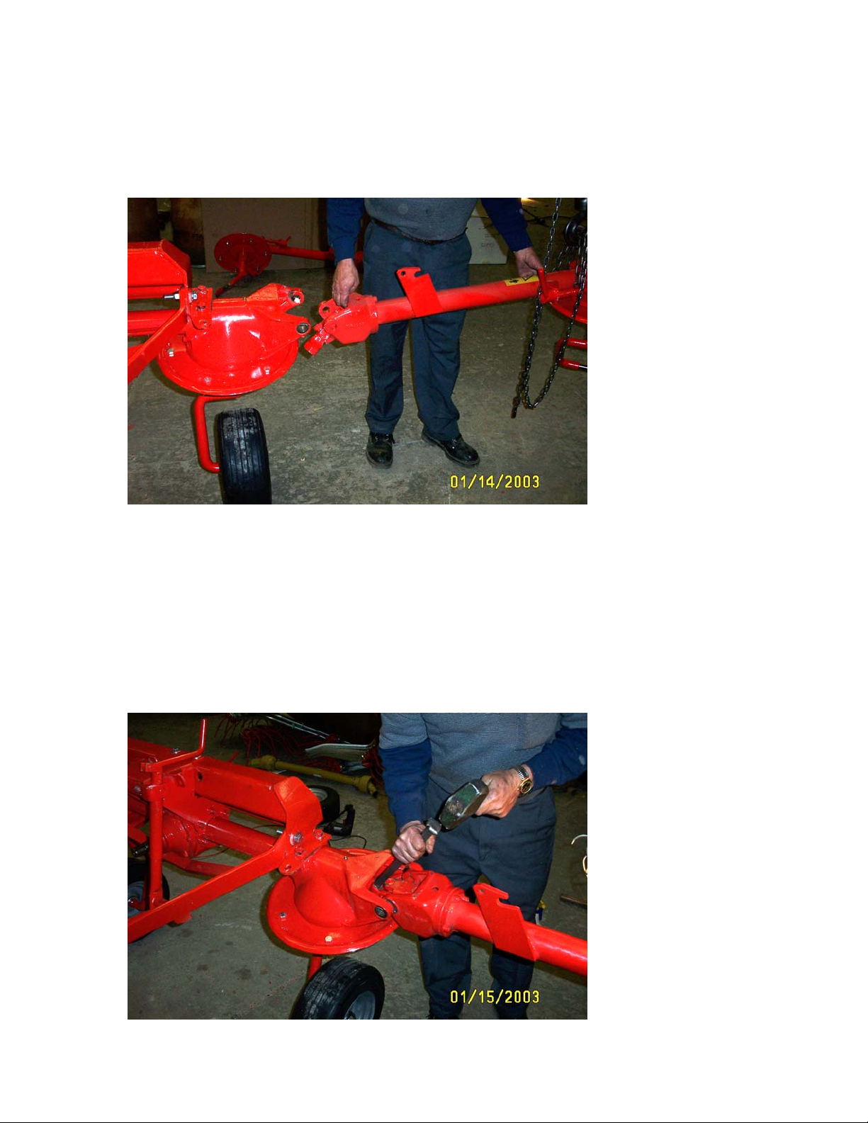
You will need to start the yokes of the arm onto the shaft & tamp them
on with a rubber hammer until it is completely in position.

7
11. Install the grease bolts back in to hold the arm on the unit and
place the rubber covers back into place.
12. Install the outer guard for the unit with the 2 bolts provided in
the outer rotor housing- you will need 19mm socket

8
13. Lift the arm into an upright position & install the hydraulic
cylinder assembly.
*Note-That there may be 2 different kits with unit for hydraulics.
Use only the applicable kit.
You will need to carefully try to remove any paint from the cylinder
shaft. After the cylinder is secure, push upward on the arm and lock
into place.
13. Attach the manual rope release with the rope, thimbles and rope
clamps provided. One rope is longer than the other. After each is
attached to either side, simply pull taut and clamp together for one
pull.
Release
Lock

9
14. Hooking up the hoses: Install hydraulic valve onto the longest
hydraulic hose using a 19 mm wrench. Be sure to insert brass washer
w/rubber insert. Screw hose adapter into the adapter into the other end
of the on/off valve using a 27mm wrench. There is a brass fitting that
goes between the adapter and the tractor end fitting.
15. Attach the short hoses to the main hose using the compression
tee fitting. (19mm wrench) Be sure to apply the pipe dope to
the threads of the compression fitting.
Hose
Valve
Washer w/ insert
Adapter
Brass washer
Tractor end

10
16. Attach the other end of short hoses to the cylinders. Be sure to
put brass washer on either side of bolt (19mm wrench).
16. Be sure to attach the safety cover around the input shaft
before attaching the pto shaft. The unit is now ready to
attach the tines.
17. The tines are already mounted on the arms. You will need to
make sure that the arms are mounted so that the tines are
facing the right direction
Brass washers
Hydraulic hose
Attaching bolt
Arms mount
with two bolts on
underside
This manual suits for next models
1