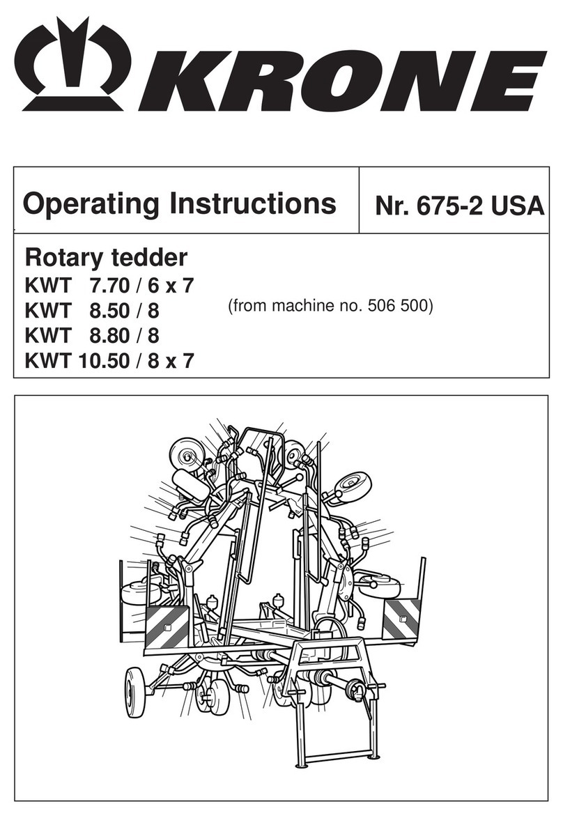
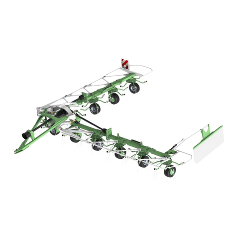
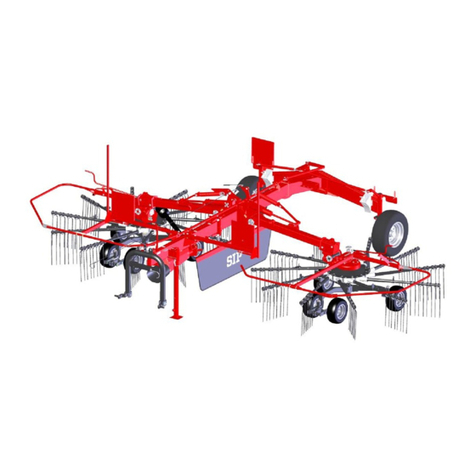
SaMASZ P4-471 User manual

SaMASZ Sp. z o.o.
Poland, 16-060 Zabłudów, ul. Trawiasta 1
Established
–
1984
NIP PL-966-159-29-76
tel. (+48) (85) 664 70 31
fax (+48) (85) 664 70 41
e-mail: samasz@samasz.pl
www.samasz.pl
OPERATOR’S MANUAL
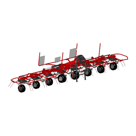
ROTARY TEDDER
P4 - 471 – 4 rotors
P4 - 531 – 4 rotors
P6 - 651 – 6 rotors
P6 - 771 – 6 rotors
IN0683EN000
2015.05.07
EDITION No 0
The original instruction
Serial No.:

CAUTION:
Company SaMASZ is working constantly on development of
all types and models. That is why, there is always a possible
change of form, equipment and technology of delivered
products. Any claims arising from data, drawings and
descriptions included in this operator’s manual and spare parts
list cannot be laid.
CAUTION:
It is forbidden to start the drive of the tedder before putting
the machine into working position.
CAUTION:
The manufacturer reserves the right to introduce changes in
construction.
CAUTION:
Tedder's components bent after coming across an obstacle or
stones are done as paid repaires.
CAUTION:
Lifting the tedder before the working units have come to
a complete standstill is forbidden.
CAUTION:
Operating is forbidden when any person is within the danger
area of 50 m.
CAUTION:
Keep this manual for future reference.
Well-proven design with thousands of machines in regular use in many countries and
quality materials ensure high durability and reliability of SaMASZ tedders.
We congratulate you on the purchase of your new SaMASZ tedder and wish you
much pleasure and the very best work results through the years to come.

Operator’s manual Rotary tedder P4 – 471 and P4 – 531
Rotary tedder P6 – 651 and P6 – 771
- 1 -
Contents page
1.
IDENTIFYING THE MACHINE................................................................................................2
2.
INTRODUCTION .........................................................................................................................2
3.
PROPER USE ................................................................................................................................3
3.1.
Technical data...........................................................................................................................3
3.2.
Design and working principle ..................................................................................................4
3.3.
Standard equipment and spare parts .........................................................................................5
4.
SAFETY ADVICE.........................................................................................................................5
4.1.
Safety rules and regulations......................................................................................................5
4.2.
Transport...................................................................................................................................7
4.2.1.
Putting the machine onto another vehicle for transport.......................................................7
4.3.
Working parts ...........................................................................................................................9
4.4.
PTO shaft..................................................................................................................................9
4.5.
Hydraulic assembly ..................................................................................................................9
4.6. Residual risk................................................................................................................................9
4.6.
Safety decals and their meaning .............................................................................................10
5.
OPERATION...............................................................................................................................12
5.1.
Switching tedder from transport position (for loading) to working position .........................12
5.2. Attaching the tedder to the tractor ............................................................................................13
5.3.
Preparing the tedder for transport...........................................................................................14
5.4.
Preparing the tedder for transport on public roads .................................................................15
5.5.
Mounting PTO shaft ...............................................................................................................16
5.6.
Switching from transport to working position........................................................................17
5.7.
Preparing the tedder for work.................................................................................................18
5.8.
Operation ................................................................................................................................20
5.8.1. Tedding on left and right side.............................................................................................21
5.9. Clogging....................................................................................................................................22
5.10. Dismounting machine from tractor.........................................................................................22
6.
MOUNTING AND ADJUSTMENTS........................................................................................22
6.1.
Mounting of the tines..............................................................................................................22
6.2.
Daily maintenance ..................................................................................................................23
6.3.
After-season maintenance and storing....................................................................................24
7.
LUBRICATION ..........................................................................................................................24
7.1.
Intersecting axis gears ............................................................................................................24
7.2.
Joints.......................................................................................................................................25
7.3. Risks present when lubricating .................................................................................................26
8.
DEFECTS AND THEIR REPAIRS...........................................................................................27
9.
DISASSEMBLY AND WITHDRAWAL FROM USE ............................................................27
9.1.
Disassembly............................................................................................................................27
9.1.1. Restarting the machine after repairs or longer storing periods...........................................27
9.2.
Demontage and scrapping ......................................................................................................27
10.
WARRANTY CARD ................................................................................................................28
11.
WARRANTY TERMS..............................................................................................................28
11.1.
Warranty claims procedures ...................................................................................................28
11.2.
Warranty repairs record..........................................................................................................29

Operator’s manual Rotary tedder P4 – 471 and P4 – 531
Rotary tedder P6 – 651 and P6 – 771
- 2 -
1. IDENTIFYING THE MACHINE
Data plate is mounted to the tedder’s main frame in the place shown below (Fig. 1).
Fig. 1. Data plate place Fig. 2. Data plate
Data plate includes:
-
name and adress of the
manufacturer,
-
model year,
-
CE marking means, that the produce
-
version number,
conforms to 2006/42/EC Directive and
-
machine weight,
harmonized standards,
-
id number,
-
machine symbol,
-
barcode.
-
date of manufacture,
CAUTION:
In case the operator's manual is unclear or illegible all necessary information
can be obtained from manufacturer or the dealer.
2. INTRODUCTION
This operator’s manual should be considered as the basic tedder’s equipment. If the tedder is
handed over to another operator, it should be in working condition and given away along with
operator’s manual and it’s other basic equipment.
Operator’s manual is attached to every machine in order that the operator can familiarize
himself with design, working principles, service and adjustment of the tedder. The user of
the tedder should be familiar with common safety rules and procedures.
The tedder is manufactured according to international safety rules.
Compliance with the warnings in this operator’s manual will ensure safe operation.
Please contact your dealer if you have any queries relating to the operation and service of
the tedder.
Operator’s manual remains part of tedder’s equipment.
GENERAL WARNING
When operating the tedder please comply with the warnings and safety
regulations shown throughout this manual by this safety alert symbol
.
CAUTION:
Operation of the tedder before reading the operator’s manual carefully as
well as operating by the unauthorized staff, especially by children, is strictly
forbidden.

Operator’s manual Rotary tedder P4 – 471 and P4 – 531
Rotary tedder P6 – 651 and P6 – 771
- 3 -
3. PROPER USE
Rotary tedder is designer to tedding cut forage and dry hay in order to accelerate their drying
process.
CAUTION:
Use of the tedder for other purposes than the above mentioned is forbidden.
Different use than the above mentioned will be considered as improper and
may lead to revoking of the warranty. Tedder should be used, operated and
repaired only by people familiarized with its detailed specifications and with
safety rules and regulations. Willful changes of the tedder will lead to
revoking of the warranty.
3.1. Technical data
Tab. 1. Technical data
Tedder’s type: P4-471 P4-531 P6-651 P6-771
Working width [m] 4,70 5,30 6,50 7,70
Transport width [m] 2,95 2,95 2,95 2,95
Transport height [m] 2,50 2,70 3,60 4,00
RPM 540
3-point linkage category II
Tractor’s power [HP] 30 40 50 50
Number of rotors [pcs] 4 4 6 6
Number of arms [psc] 6 6 6 6
Max. working speed [km/h] 16 16 16 16
Tires 16 x 6,50
Recommended pressure [bar] 2,2
Weight [kg] 665 680 940 945
Noise level L
pA
66,3 ± 3,2 dB
L
Amax
69,5 ± 3,2 dB
L
Cpeak
92,0 ± 3,2 dB

Operator’s manual Rotary tedder P4 – 471 and P4 – 531
Rotary tedder P6 – 651 and P6 – 771
- 4 -
3.2. Design and working principle
Overview of rotary tedder is provided on Fig. 3. 3-point linkage frame (1) with catch (2)
enables connecting tedder to the tractor 3-point linkage suspension. Drive with tractor PTO is
transmitted by intersectional gears onto rotors. The tedder comprises of three (five for P6 - 651 and
P6 - 771) drive units: left and right (3and 4) as well as main one, onto which rotors are set with
arms (5) and fingers (6). Safety guards (7) are mounted on the frame and lateral drive units. For
transport the two lateral units with rotors are folded by hydraulics to vertical position and locked
with a lock (8).
Fig. 3. Parts of SaMASZ rotary tedder
1 – 3-point linkage frame
2 – Catch
3 – Left drive unit
4 – Right drive unit
5 – Raking arms
6 – Spring tines
7 – Safety guards
8 – Locking pawl
9 – Ground following mechanism
10 – Plates with luminous and reflecting elements
11 – Chain for operating position adjustment
12 – Chain for operation in very uneven ground
13 – Holder for warning triangle for slow driving vehicle
14 – Support wheel (optional)
The tedder has been equipped with ground following mechanism (9) enabling for following
the ground unevenness by the machine with use of 3-point linkage suspension stiff connector.
The tedder may be equipped with (optional) support wheel (14). Chain (11) for operating
position adjustment of the tedder and chain (12) for operation on very uneven ground to be used
instead of the stiff connector. Chain (12) is used when adaptation range of the mechanism (9) is not
sufficient.
When driving on public roads the tedder should be equipped with a plate with luminous and
reflecting elements (10), and a warning triangle for a slow driving vehicle mounted on the holder
(13).
3
5 8 17 1010 7
5
1214 611
7
43 4
9
13
27 7
6

Operator’s manual Rotary tedder P4 – 471 and P4 – 531
Rotary tedder P6 – 651 and P6 – 771
- 5 -
50h
50h
50h
3.3. Standard equipment and spare parts
The tedders are sold with the following standard equipment:
warranty card,
operator’s manual with spare parts list,
PTO shaft with friction clutch,
warning plate,
operating position adjustment chain,
chain for operation in very uneven ground,
spray paint (150 ml).
Tab. 2. Recommended PTO shafts for rotary tedders
Model Power Length Moment
Symbol Clutch Manufactu
rer
Notes
HP mm Nm
P4-471
P4-531 21 1210-1733 270 8G2N121CE007002 friction Bondioli &
Pavesi -
P6-651
P6-771 35 1210-1725 460 8G4N121CE007003 friction Bondioli &
Pavesi -
Fig .4. PTO shaft lubrication points. Mounting directions
WARNING:
The frequency of lubrication of the articulated telescoping shaft should be
carefully adhered to. Points shown on Fig. 4 should be lubricated every 50
hours. The articulated telescoping shaft should also be lubricated before and
after longer periods of disuse.
PTO shafts of other brands with equivalent parameters could be used after SaMASZ permission.
4. SAFETY ADVICE
4.1. Safety rules and regulations
Front axis of the tractor should be weighted to keep the balance. If need be, use front wheel
weights.
Any operation with the hydraulic lift lever should be done from the operator’s seat; DO NOT
move the lever from outside of the tractor.
In case of tractors equipped with EHR, operating with hydraulic lift is done by the buttons
mounted outside the tractor’s cabin. When operating be extremely careful.
When switching from working to transport position unmount the whole or at least one end (from
tractor’s PTO) of PTO shaft.
Operation without safety guards as well as with the damaged guards is not allowed.
PTO shaft’s end without
clutch –
To be mounted on the
tractor’s side
PTO shaft’s end with friction
clutch –
To be mounted on
tedder’s side

Operator’s manual Rotary tedder P4 – 471 and P4 – 531
Rotary tedder P6 – 651 and P6 – 771
- 6 -
Start tedding only when the tractor’s PTO reaches its nominal rpm.
Nobody is allowed to remain within the danger area of at least 50 m. Particular caution is
necessary when operating near roads and in stoney areas.
Any maintenance and adjustment work should only be done after the drive has been
disconnected and the rotors are in standstill.
When driving on public roads always comply with local traffic regulations, especially
concerning warning lights.
CAUTION:
Any operations related to service and repair works on the tedder should be
conducted with the tractor drive off, and all rotating parts in the complete
standstill.
CAUTION:
Be certain that children and animals are at a safe distance away from the
machine. Never allow anyone to ride on a machine or tractor.
When the tedder is lifted for repair on the 3-point linkage, it should be secured against
falling by a mechanical support or by chain.
The bolts and other fasteners have to be periodically checked and, if necessary, tightened or
replaced. DO NOT work with damaged or worn fasteners.
Never lift the tedder on tractor linkage when the drive is on and the rotors are rotating.
During operation of the tedder the Regulation of the Farm Ministry and Food Economy from
12-01-1998 dealing with safety and hygiene during the operation of tractors, machinery, tools
andequipment used for farming (Dz. U. Nr 12/98 poz. 51), should be observed,
When operating the tedder, the tractor should always be equipped with the cabin.
Tedder should not be operated when the tractor-tedder set is not balanced.
Never start the tedder when it is lifted.
Never start the tedder, when people or animals are near the machine.
Always comply with safety decals describing hazards, and warning signs placed on
the machine.
Before you start the tractor make sure that every other drives are turned off and the levers
steering hydraulics are in neutral position.
Never leave the tractor’s engine running without supervision. Before you leave the tractor, turn
off the engine and put off the key from tractor’s ignition switch.
It is forbidden to operate the tedder when driving backwards.
Never get on the tedder.
Never lift the tedder on tractor’s 3-point linkage when the drive is on and the rotors are rotating.
Never stand between tractor and tedder, before tractor-tedder set is secured against moving by
the tractor’s brake.
Every maintenance work and regulations can be done only when the tedder is on the ground.
If any maintenance work or regulation under lifted tedder is needed, it must be secured against
falling.
When the parts of the tedder need replacement, use only the original spare parts according to
spare parts list.
Pay particular attention to PTO shaft’s guards and tedder’s and tractor’s spline shaft guards.
Never work with damaged guards.
Hydraulic hoses should be periodically checked and if any damage occur or they expire, replace
with new ones. Expiry period should not exceed 5 years.
Never use scotch tape to repair hydraulic hoses.

Operator’s manual Rotary tedder P4 – 471 and P4 – 531
Rotary tedder P6 – 651 and P6 – 771
- 7 -
When connecting hydraulic hoses to tractor’s hydraulic connectors make sure, that either
tractor’s or tedder’s hydraulic system is without pressure.
When operating hydraulic system, always wear protective gloves and glasses. Leaking under
pressure hydraulic oil (16 MPa) may permeate through the skin and cause infection. If it
happens, immediately visit a doctor.
The tedder should be stored under roofed places and in the way that it will not harm people or
animals.
Do not leave agricultural machinery on slopes or other descents without providing protection
against its free runaway.
Due to risk of tipping, it is not permissible to fold rotors for work on cants (across the slope).
Setting the machine should be performed on an even ground or upwards/down the slope.
When operating over a stony field or nearby roads there exists a risk of throwing out stones or
other objects, which may pose a danger for passing-by vehicles on the road or for passers-by.
Therefore keep the safe distance.
Rotating spring tines and other rotary elements present a danger to health and life of persons
present nearby the machine. Do not touch any moving machine parts.
The operator is not allowed to leave the tractor while driving.
Before transporting the tedder make sure that the support leg is lifted and protected.
Prior to approaching operation with the machine, make sure that all safety guards are not
damaged and fitted in place.
Check pressure in the machine's wheels regularly.
In the event of any break in the equipment operation, turn off the drive.
Bear in mind that when operating and transporting the machine in areas where high voltage
lines are present, special caution should be exercised due to possibility of contacting the
aggregate with the lines.
Prior to performing any maintenance works set the machine onto a stable ground and protect
against unintentional shifting.
In case of a fatal failure, stop the machine's drive, turn the tractor's engine off and take out the
ignition key. Then call for technical service, and if an accident (in this case: road accident)
occurs, respect first aid rules and contact responsible authorities.
4.2. Transport
Every position change of the tedder can only be done when there is nobody around (pay
particular attention to children).
When driving on public roads, the tedder should be equipped with warning plates with luminous
and reflecting elements, and a warning triangle for a slow driving vehicle.
During transport always put the tedder to transport position. See chapter 5.3.
Before putting the tedder to transport position make sure, that the tractor’s PTO is turned off
and all the rotating parts have come to complete standstill.
Driving speed should always be adjusted to road conditions.
Permissible speed is 30 km/h and it cannot be exceeded.
4.2.1. Putting the machine onto another vehicle for transport
The driver and the carrier are responsible for tedder’s transport safety. Equipment and parts
must be secured during transport.
To put the tedder onto another vehicle in a safe way, please obey the following rules:
seize the tedder by any lifting devices only in the places indicated by the hook sign (Fig. 5),
for tedder lifting use only lifting devices with hoisting capacity bigger than tedder’s weight
shown in data plate. It also concerns ropes and chains used for lifting,

Operator’s manual Rotary tedder P4 – 471 and P4 – 531
Rotary tedder P6 – 651 and P6 – 771
- 8 -
transport belts, belt suspensions, ropes cannot be damaged. Whenever damages to these parts
are spotted replace these with new ones,
when mounting slings, chains, handles etc. always pay attention to setting the machine's center
of gravity properly,
to catch machines, pick ropes of adequate length, so that the angle between them is no greater
than 120°, and the angle between the strand and the vertical is no greater than 60°,
collapsible parts should be blocked in transport position,
during putting the tedder onto another vehicle it is forbidden for anybody to remain in transport
area,
on the vehicle’s trailer the machine should be secured against moving.
CAUTION:
Securing maneuvering area and transport of the tedder is the responsibility of
a person who does it.
Fig. 5. Tedder’s catching points Fig. 6. Location of centre of gravity
Tab. 3. Location of centre of gravity
Dimension
[mm]
Type
P4-471 P4-531 P6-651 P6-771
X
1010
1030
1400
1400
Y
780
755
720
690
B
B
A
X
X
Y

Operator’s manual Rotary tedder P4 – 471 and P4 – 531
Rotary tedder P6 – 651 and P6 – 771
- 9 -
4.3. Working parts
Before operating the tedder check rotors’ and tines’ condition.
Worn or damaged tines should be immediately replaced with new ones.
4.4. PTO shaft
Before operating learn provisions found in bar manufacturer's manual placed on the bar.
Use only PTO shafts recommended by tedder’s manufacturer.
In order to operate safely use only fully technically fit, undamaged PTO shafts. Damaged PTO
shaft shall be repaired or replaced with new one.
4.5. Hydraulic assembly
Caution! Hydraulic assembly is under pressure! Hydraulic oil under pressure may permeate
through skin and cause serious injury, therefore skin and eyes should be protected in particular.
In case of injuries caused by a liquid under pressure, call a doctor immediately.
Hydraulic hoses can be connected to tractor's hydraulics, provided that both the tractor’s and the
tedder's hydraulic assemblies are not under pressure. To remove the pressure from the hoses just
simply restart the tractor's hydraulic valves several times, once the tractor is off.
When dismounting the machine from the tractor, set the equipment aside, deflate the pressure
from hydraulics and turn tractor's engine off.
When controlling for hydraulic assembly's malfunction and looking for oil leaks, it is forbidden
to touch any potential leaks until the entire assembly is under pressure.
Note! It is recommended to use hydraulic oil featuring oil purity class 9 - 10 in accordance
with NAS 1638.
When using hydraulic hoses:
Avoid stretching the hoses when operating.
Do not allow hydraulic hoses to get deflected.
Do not expose hydraulic hoses to contact with any sharp edges.
If damaged or worn, replace the hoses with new ones.
Useful life for hydraulic hoses is 5 years from their production date.
4.6. Residual risk
Despite the fact, that company SaMASZ Białystok – the manufacturer of the tedder takes
the responsibility for design and manufacturing of the tedder, in order to eliminate dangerous
situations, certain risk during tedder operation is unavoidable.
1. Danger of catching
This kind of risk occurs during changing the position of a tedder, operation near rotating
parts, working without safety guards.
During operation, maintenance and regulations always wear protective gloves, shoes and
clothes without loose parts, belts and so on. Always comply with safety decals placed on the tedder.
2. Danger of injury
This kind of risk occurs during replacement of working parts with sharp edges. During any
maintenance work always use safety gloves.
3. Danger of liquid ejection out of hydraulic system
During connection of hydraulic hoses to hydraulic connectors make sure, that either tractor’s
or tedder’s hydraulic system is without pressure.
During operation of hydraulic system always wear protective glasses and gloves. Check
regularly hydraulic hoses.

Operator’s manual Rotary tedder P4 – 471 and P4 – 531
Rotary tedder P6 – 651 and P6 – 771
- 10 -
CAUTION:
Residual risk always results from incorrect behaviour of tedder’s operator.
4. Bans
Please bear in mind the following bans during tedder’s operation:
never unblock the tedder, make any regulations or repairs while the tedder is in motion,
never change the order of operation and maintenance activities described in operator’s manual,
never operate the tedder when it is not in working order or has damaged safety guards,
never get your hands and legs close to rotating parts of the tedder,
during repair and maintenance of the tedder always comply with the descriptions included in
operator’s manual. Always do these activities when the tractor’s drive is off,
before you start any activities, focus your attention on them,
never operate the tedder under the influence of alcohol, drugs, or strong medicines
your clothes should not be too loose, or too tight. Too loose cloth parts may be pulled in by
the rotating parts of the tedder.
the tedder cannot be operated by children or by handicapped people
When describing residual risk, the tedder is treated as a machine, that up to the moment of its
putting in motion it had been designed and manufactured according to technology level actual till
the day of tedder’s manufacture.
CAUTION:
Residual risk occurs in case of not complying with described instructions and
bans.
When the risk of exposing to noise cannot be avoided or eliminated by any group
protective means or organization of work, employer (farmer) must:
1) provide the operator with individual means of noise protection, if the noise
level in work place exceeds 80 dB.
2) provide the operator with individual means of noise protection and supervise
the correctness of its usage, if the noise level in work place reaches or exceeds
85 dB
.
4.6. Safety decals and their meaning
CAUTION:
a) all warning decals should be clean and legible,
b) lost or damaged decals must be replaced,
c)
please order new decals from your dealer or supplier.
N-1
Be extremely careful when PTO
shaft is rotating
N-3
Read the operator’s manual
before putting the tedder into
operation
N-4
While making repairs the
machine must be stopped

Operator’s manual Rotary tedder P4 – 471 and P4 – 531
Rotary tedder P6 – 651 and P6 – 771
- 11 -
N-6
CAUTION: pulling-in parts
N-7
Operating is forbidden when any
person is within the danger area
of 50 m
N-9
CAUTION: rotor
N-40
Signs indicating transport holders
N-49
Never stand near tractor’s
3-point linkage while steering
tractor’s lift
N-50
Do not stay in the swinging area
of tedder’s parts
N-11
N-52
Wear protective gloves
N-55
N-198
P-3
N-202
Admissible transport speed
N-62
N-162
N-67
N
-
68
N-183
Caution: danger
of leg drawing

Operator’s manual Rotary tedder P4 – 471 and P4 – 531
Rotary tedder P6 – 651 and P6 – 771
- 12 -
N-29
Fig. 7. Warning decals placed on the tedder
5. OPERATION
5.1. Switching tedder from transport position (for loading) to working position
(Applies to tedder P6-651 and P6-771)
Due to permissible loading height for trucks tedder P6-651 and P6-771 is prepared for
transport in special manner Fig. 8a.
In order to prepare the machine for loading dismount pin A from eye found in shaft’s
housing B(Fig. 8b ) and position two extreme most rotors vertically.
Fig. 8. Tedder P6-651 in compact position for transport on public roads
a)
B
A
b)

Operator’s manual Rotary tedder P4 – 471 and P4 – 531
Rotary tedder P6 – 651 and P6 – 771
- 13 -
In order to prepare the machine for operation, perform the following:
carefully (either manually or by means of loader) lower vertically positioned extreme most
rotors,
unlock pawls and eject cylinders,
remount previously dismounted pin A(Fig. 8a) as provided on Fig. 9,
lift the tedder by means of hydraulic cylinders.
Fig. 9. Mounted cylinder lever
CAUTION:
Switching tedder from compact position for transport to working position
without having mounted the pin shall lead to damaging cylinder and
cylinder lever, which is therefore, not covered by warranty.
5.2. Attaching the tedder to the tractor
The tedder should be mounted on tractor with use of 3--point linkage as provided on Fig. 10.
Upper link Gshould be mounted on pin S1 in the catch eye (Fig. 10b), hangers Wfor tractor's
lower links should be placed on pins on the tedder's linkage frame (Fig. 10a).
Chain L shall be placed on the top link pin in order to protect the rake from falling of hangers
W.
Lift up support legs (Sp) and secure them with pins.
Connect the machine's hydraulic hose to the tractor one-section hydraulic connector.
Connect the machine's lighting cables to the tractor and check the lights for operation (optional).
Connect telescopic articulated shaft. If need be shorten the shaft as per item 5.5.
Fig. 10. Connecting the tedder to the tractor
A
B
S1
S2
S1
G
b
C
G
W
L
a
Sp

Operator’s manual Rotary tedder P4 – 471 and P4 – 531
Rotary tedder P6 – 651 and P6 – 771
- 14 -
In order to perform this, the tractor should be weighed and then driven onto the scales with
the tractor's front axis only (tedder must be in transport position, so lifted upwards). If the pressure
on the front axis is at least 20% of the whole set’s pressure, it means the set is stable. If not, the
front axis should be balanced.
5.3. Preparing the tedder for transport
To prepare the tedder for transport and to meet safety precautions, please do the following:
replace the linking chain for stiff connector, transport of tedder with chain instead stiff
connector may cause damage to the machine and the tractor,
CAUTION:
Stiff connector must be used when tedder is transported. Transport with no
connector may cause damage to the machine or the tractor.
by means of hydraulic cylinder lift two outsid rotors of the tedder until the locs Z are latched
(Fig. 11),
CAUTION:
Prior to folding tedder to transport position for tractor with PTO shaft
automatic lock, the PTO shaft shall be disconneted from tractor. Keeping the
shaft connected may cause damage to drive shafts.
Fig. 11. Locks in transport position
lift the tedder with tractor hydraulic lift until the lower lift pins of the tedder 3-point linkage
frame raise about 50 cm above the ground,
lift and secure support leg S,
if needed adjust the tedder drive wheels so its transport width when driving on public roads is
not greater than 3 m (Fig. 13).
Z
Z

Operator’s manual Rotary tedder P4 – 471 and P4 – 531
Rotary tedder P6 – 651 and P6 – 771
- 15 -
Fig. 12. The tedder in transport position
CAUTION:
When lifting the machine for transport pay attention so that the tractor's
glass pane is closed. Protective barriers found on the tedder may
damage the glass.
5.4. Preparing the tedder for transport on public roads
To meet safety precautions concerning transport on the public roads in Poland the tedder
should be equipped with two warning plates T (Fig. 13). The plates are in standard equipment of
the tedder.
CAUTION:
The warning devices can be ordered from the tedder manufacturer.
max 4,0 m

Operator’s manual Rotary tedder P4 – 471 and P4 – 531
Rotary tedder P6 – 651 and P6 – 771
- 16 -
Fig. 13. The tedder transport width change
When driving on public roads the machine overall width should not be greater than 3 m. Since
the SaMASZ tedder operating height of drive wheels can be is adjustable, change of this setting
may lead to alternation of the machine transport width when folded. Therefore, the tedder transport
width should be controlled prior to driving onto public roads and if needed wheels 1setting should
be changed (Fig. 13).
CAUTION:
Transport width of tedder P6 – 771 may exceed 4 m as main wheels of the
tedder are lifted above 100 mm from the ground.
5.5. Mounting PTO shaft
Prior to commencing operation, examine and adjust length of PTO shaft, which is designed to
mount machine on tractor. In some cases it is possible, that the shaft is too long and therefore needs
to be shortened, so that there is adequate tolerance for the shortest possible distance between
tractor’s shaft and machine’s shaft.
PTO shaft’s end with friction clutch should be mounted on tedder’s side.
When connecting PTO shaft between tractor and tedder make sure, that external guard tube of
the shaft is on the tractor’s side. The PTO shaft plastic guards have to be secured by fastening their
small chains to immovable parts of tractor and tedder.
1
Transport width
Lt< 3,0 [m]
T
T
Transport width
of more than 3 m
Transport width of less than 3 m

Operator’s manual Rotary tedder P4 – 471 and P4 – 531
Rotary tedder P6 – 651 and P6 – 771
- 17 -
CAUTION:
Use the machines with PTO shafts designed to drive them. Before the work
begins, check the safety guards (in tractor, tedder and PTO shaft), if they are
placed correctly and are not damaged. Damaged or lost parts must be
replaced with genuine ones. Make sure the PTO shaft is properly mounted. It
is forbidden to approach the rotating parts, because it may lead to serious
injuries or even death. All service and repair operations must be done only
after the tractor engine has been stopped, all rotating parts have come to the
complete standstill and the machine is on the ground. Before the operation
begins, read operator’s manuals of both the machine and PTO shaft.
CAUTION:
If need be, shorten the PTO shaft according to its operator’s manual given by
the shaft’s manufacturer (Fig. 15).
Fig. 14. Instruction of PTO shaft shortening
CAUTION:
PTO shaft’s end with friction clutch should be mounted on tedder’s side.
CAUTION:
The PTO shaft should be mounted only during operation time and
disconnected from tractor PTO for transport and service.
5.6. Switching from transport to working position
make sure there is nobody around in the place where you are going to lower the tedder,
with tractor’s lever lower the tedder to reach the horizontal position in a possibly slow way,
by means of cord L (Fig. 15) unlatch the locks Z (Fig. 11) at the same time pulling down
the hydraulic cylinders,
by means of hydraulic cylinder lower the rotors until they are on the ground in a possibly slow
way.

Operator’s manual Rotary tedder P4 – 471 and P4 – 531
Rotary tedder P6 – 651 and P6 – 771
- 18 -
Fig. 15.Unlatching the lock by means of a cord
SaMASZ tedders are equipped with repellent mechanism for mobile tedder arms. Thanks to
it, arms can be folded with no need of leaving the tractor cabin. It may however be limited by
the slope, on which the machine is being folded. Presumably, the mechanism shall operate well on
slopes of up to 4° (Fig. 16).
Fig. 16. Tedder folding mechanism limitation
5.7. Preparing the tedder for work
CAUTION:
During storing of the machines in company SaMASZ the cylinders are
protected by special grease in order to secure them against weather which
may cause their premature wear. Before starting the operation excess grease
should be removed from the cylinders.
L
Automatic
unfolding
Other manuals for P4-471
1
This manual suits for next models
3
Table of contents
Other SaMASZ Tedder manuals