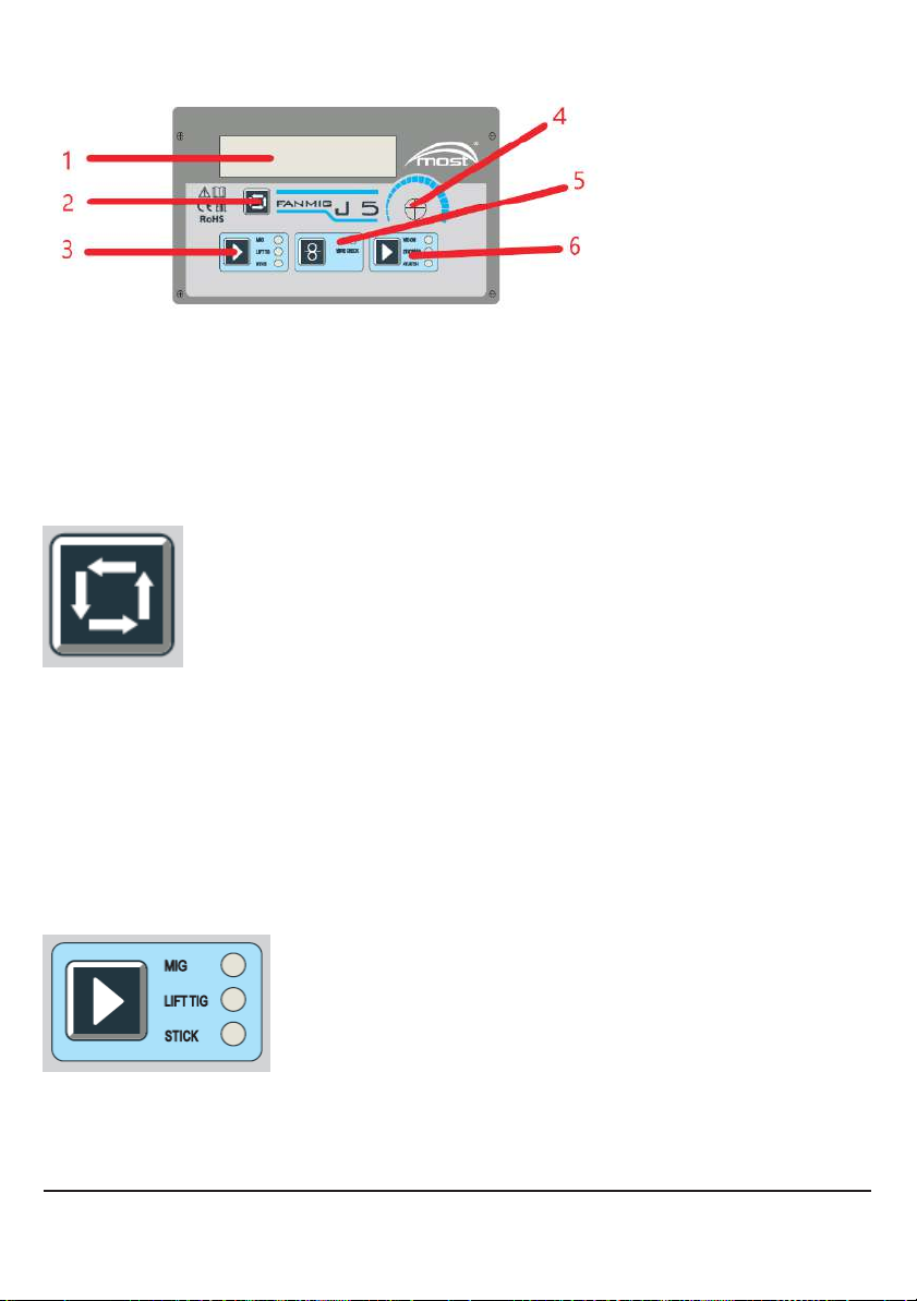
7. MIG/MAG welding technique
7.1 Power connections
The device is powered from a three-phase 230V 50/60Hz. Required protection by a 16A
slow-blow fuse
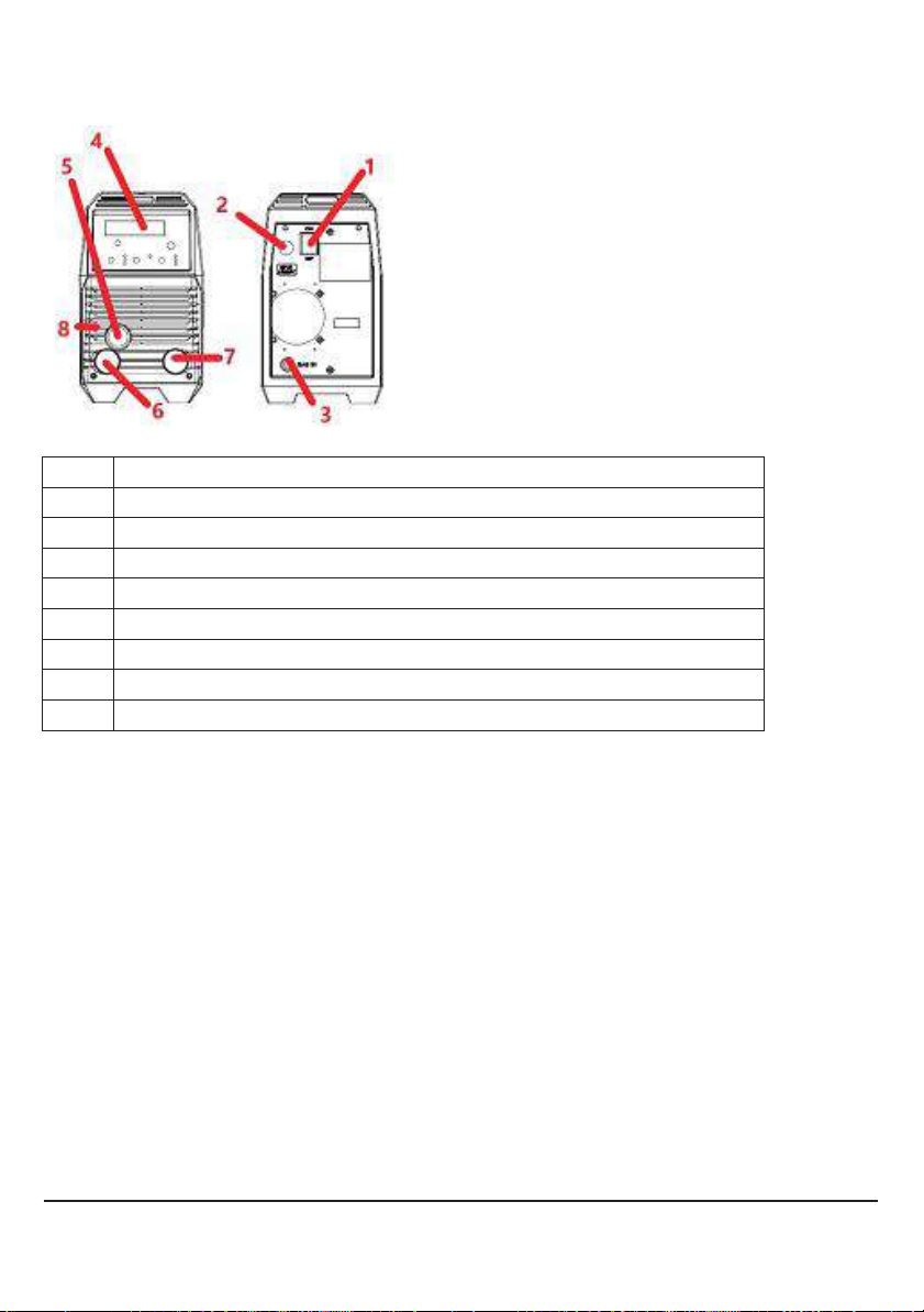
7.2. Welding torch connection
The welding torch should be connected with euro socket (pos. 5 Fig.1) and tightened with a nut.
The torch insert and contact tip must refer to welded wire diameter –see current RYWAL-RHC
catalogue.
7.3 Feed rolls in wire feeder
Each roll includes two grooves - marking is stamped on roll side.
The groove must reflect the wire type and diameter. When changing the wire, make sure that
the correct roll is applied.
Available steel welding rolls:
- V 0,6-0,8 F175i roll –cat. no. 5113007801,
- V 0,8-1,0 F175i roll –cat. no. 5113007833 (standard).
7.4 Mounting the spool on a feeder and wire feeding in welding torch.
The wire spool should be installed on the feeder sleeve so the wire unwinds from the bottom of
the spool and goes straight to feed rolls. Fanmig J5 is able to weld using 5 kg spools (e.g. type
B200) and after retooling the sleeve also using 1 kg spools.
The spool's braking force is controlled by a bolt inside the spool's sleeve. Use an Allen key to
adjust the braking force.
After unwinding a short length of wire from the spool, align the end of the wire
(cut with pliers 57 00 004707)), insert the end into the guide and then onto the feed roll - the
upper pressure mechanism raised! Than guide the wire through euro-socket and welding torch
Press the pressure arm after inserting the initial 20 cm wire section into the welding torch and
continue feeding wire automatically by pressing torch button or the (5) button according to fig. 2.
It is recommended to demount the gas nozzle and the tip contact when inserting the wire into
the torch. It is not allowed to use excessive pressure on the rolls, as it may lead to wire
deformation and feeding issues.
7.5 Gas connection and shielding gas flow setting.
Shielding gas hose connects the device to gas bottle using reducer. ARG / CO2 or argon gas
mixtures are used for welding. There is a nipple ( 3) on the back of the device (Fig. 1) for
connecting the gas.
The cylinder must be positioned in a stable manner and secured against falling over, eg.
chained to a wall. It is possible to use trolleys to transport the device together with the cylinder
and accessories, e.g. WUS HD MOST cat. no. 50 03 003942. Having the cylinder placed and
gas hose connected to the back of welding device, unscrew the cylinder valve and set pressure
level with the reducer. Gas flows out after pressing the torch button. Recommended gas flow
rate is 10 x the wire diameter and equals the gas flow in litres per minute.