CHIEF Multi-Spot M22AL User manual

EL900016
© January 2014 by Vehicle Service Group. All rights reserved. CO8904 Rev - 1/31/14
Operating Manual
Multi-Spot M22AL
CD Stud Welding Machine

2
OPERATION MANUAL
Read this manual carefully before using the machine.
Failure to respect the rules described herein shall exempt the manufacturer from any liability.
The machine has been designed, built and protected for the functions described below. Any other use not
explicitly included shall be considered unacceptable.
The machine must be used in suffiently ventilated rooms, in the absence of dust and moisture; in any case,
where there is no risk of fire, explosion, or flooding.
The machine must be started, used and serviced by qualified personnel. Always follow current safety
regulations.
The manufacturer shall not be held responsible for any damage caused by incorrect use of the machine.
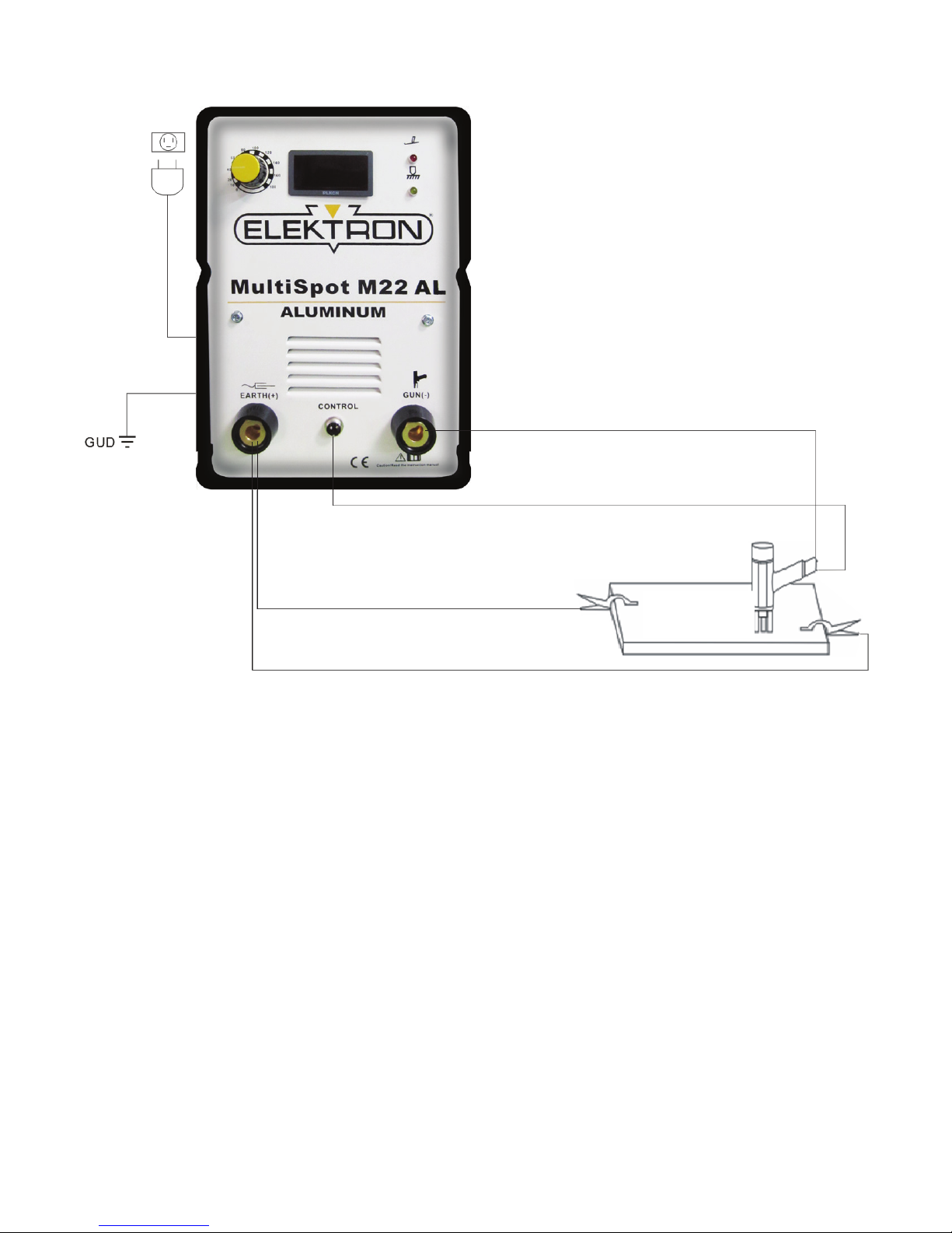
INTRODUCTION
This device must be used exclusively for stud welding on electrically conductive materials (metals and
alloys).
Welding takes place due to the high temperature generated by a concentrated electric arc, and thus highly
dangerous situations may arise; it is therefore essential to pay the utmost attention to the chapter entitled
SAFETY PRECAUTIONS.
This manual must be kept carefully in a place familiar to everyone using the machine. It must be consulted
whenever doubts arise and be kept for the entire life-span of the machine; it will also be used for ordering
replacement parts.
NOTE
*Only use original replacement parts.
*Always replace any damaged part of the unit.
*Do not use any torches other than the original.
*Do not use the unit without covers. This is dangerous for the operator and for those who are surrounding the
work area. This also prevents the unit from cooling efficiently.
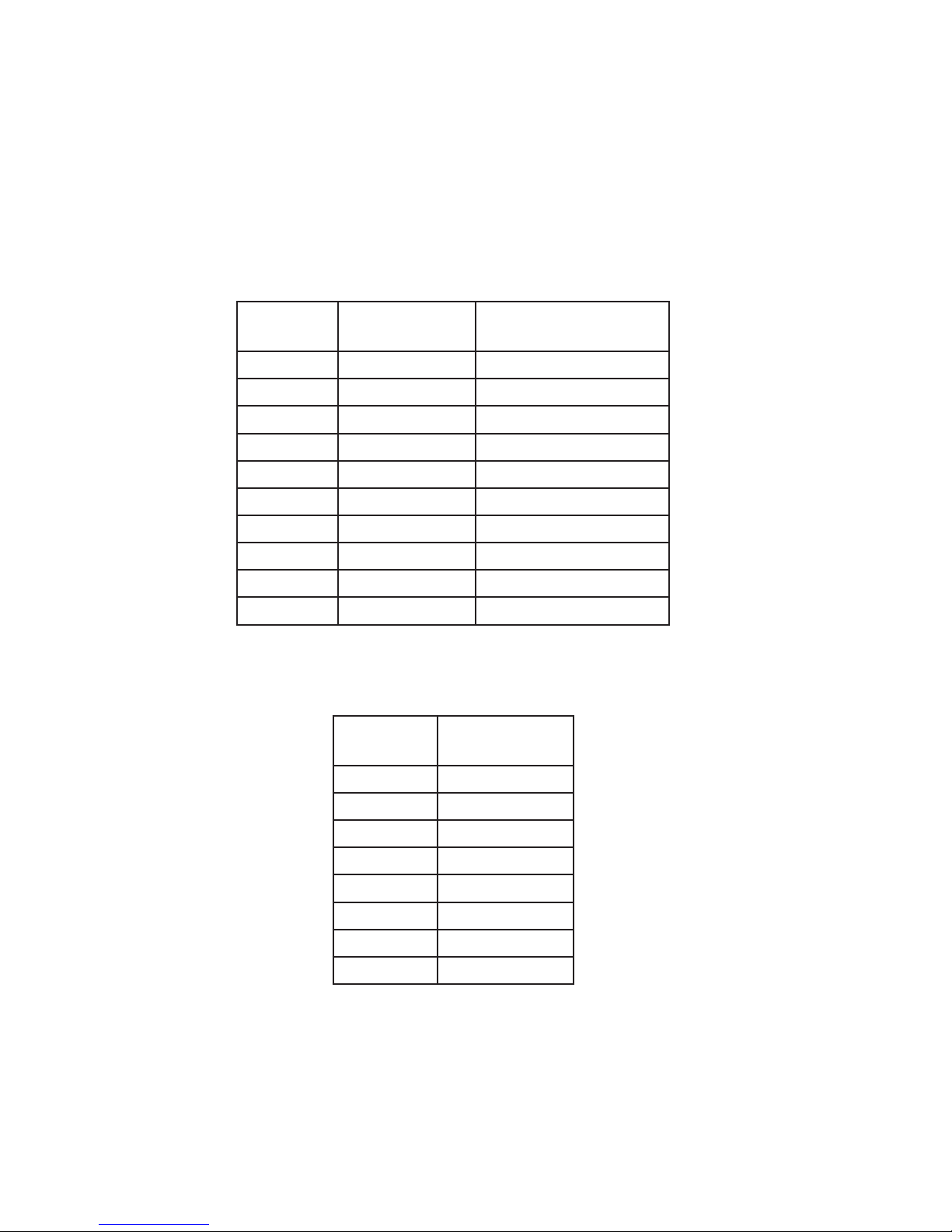
DESCRIPTION OF TECHNICAL SPECIFICATIONS
NOTE
Should there be a claim for losses or damages it must be made by the purchaser directly to the shipper who
handled the unit.
When requesting information about this welding machine please state the machine’s part number and serial
number to ensure receiving accurate information relating to your machine.
The content is for your reference.
Please be subject to the actual products if anything is different or updated.

3
BEFORE STARTING THE EQUIPMENT, READ THE CONTENTS OF THIS MANUAL.
1. Mechanical/Electrical/Illustration Of Working Principle data
Electrical Data

4
Illustration Of Working Principle

5
2. CD Stud Mode
2-1. Summary
This machine is for Capacitor Discharge Stud Welding, the weldable range is Ø3- Ø8mm. Stud materials
are soft steel, stainless steel, aluminum, titanium (Ti), brass and copper screw. Stud Welding time is about
3/1000s-6/1000s. Stud Welding time will not damage the base metal including sheet metal.
2-2. Attention
(1) Input power is AC110V 15A.
(2) Turn “off “ the switch when not using the machine.
(3) Turn “off “ the switch when connecting or removing cables on the machine.
(4) The machine maintenance and repair must turn “off “ the switch after 5 minutes.
(5) The stud clamp is located inside the stud welding torch. The inside diameter of stud clamp must be suitable
for the stud screw. Do not use a worn stud clamp.
(6) Stud welding may cause welding arcs and metal spatter, protect yourself with appropriate safety protection
and goggles.
(7) Make sure there are no flammable materials in the work area.
(8) The machine must use the required stud screws.
(9) Pleases contact the manufacturer for the following situations:
mechanical failure, reducing or increasing the torch cable length, exchanging the standard equipment.
2-3. Stud welding
Contact type: apply to soft steel, stainless steel, aluminum, titanium (Ti), brass, and copper.
Diagram 1
1.The stud screw press
the base metal
3. Stud welding complete2. electric discharge,
start arc
Secure the stud welding position. Press the torch trigger, press down, and the stud screw will be welded on the
base metal immediately. Electric discharge, stud welding, and recharge will process automatically and safely.
Traditional methods such as rivets, lock screws, and common welding can damage the base metal.

6
2-4. Stud welding visual test
Please refer to the following pictures, and evaluate the stud welding results.
If the stud welding results are unacceptable refer to Page 6. Adjusting the charge voltage, torch head pressure,
or torch head height may be necessary. (Note: adjust one setting at a time.)
2-5. Stud welding trouble shooting
The following situations may cause unacceptable results. Correct before using the machine.
(1) The earth (ground) cable and the metal are not creating a good connection.
(2) Torch cable or earth (ground) cable is twisted.
(3) The diameter of screw clamp and stud screws are incompatible, or screw clamp is worn.
(4) The base metal is dirty, rusty, painted or other issues interfering with electricity conductibility.
(5) The torch is not suitable for the base metal or stud screws.
(6) The stud screws and the base metal are not creating acceptable connections (Note: the stud screw should
contact the base metal perpendicularly).
(7) The stud welding voltage is not correct.
(8) The capacitor is damaged.
(9) The welding torch must be kept stationary with no movement.
(10) Stud screws are extending too long (or too short) from the stud clamp.
(11) Base metal distortion or movement when welding.
(12) Method for connecting the earth (ground) cable:
1. Voltage not enough 3. Too high voltage2. Correct voltage

7
Correct connection Incorrect connection
Earth
(Ground)
Earth
(Ground)
Earth
(Ground)
Earth
(Ground)
Earth
(Ground)
*Cable must contact the base metal directly and contact two earth (ground) cables.
*The earth (ground) cable must be connected diagonally on the base metal (Refer to the diagram below).

8
2-6. Stud Mode Cable Connection
CAPACITOR DISCHARGE STUD WELDING
STUD WELDING TORCH
Welding torch cable
Control cable
Earth (Ground) 2 cables
Input cable -
Connect to the
back of machine
AC 110V/230V/380V 15A
(1) Cable connections (Refer to the diagram above).
1. The torch cable and earth (ground) cables use Euro type quick connectors. Push the plug into the socket,
torch cable to “GUN (-)” socket, earth (ground) cable to “STUD EARTH (GROUND) (+)” socket, and turn right for
secure connection.
2. The input cable and control cable connectors use screws to secure connections.
3. The earth (ground) cables must be clamped to the base metal.
4. All cables should be kept straight. If the cables are twisted it will interfere with stud welding.
(2) Negative connection----apply to zinc coated steel, steel plate, plate brass, and titanium stud screws.
The earth (ground) cable connects to the “GUN (-)” socket, The torch cable connects to the “STUD EARTH
(GROUND) (+)” socket.
The torch and earth (ground) cables exchange connections.

9
2-6.1 Controls on generator front panel
A Output indicator
During machine output, the red LED will light.
A1 Connection indicator
When the torch and earth (ground) cables have a good connection, the yellow LED will light.
B Output voltage meter
C Output voltage adjustment for stud welding
D STUD torch connector
E SPOT earth (ground) connector
F Control cable connector
A
A1
B
C
DE F

10
2-7. Stud welding adjustments
Adjust stud welding according to the diameter of stud screws.
* Adjust charge voltage.
* Adjust welding torch pressure or clearance.
Stud screw adjustments are standard in the following diagram.
2-7-1 Charge voltage for soft and stainless steel stud screws:
Stud screw Change voltage
(V)
Welding torch pressure
(kgf)
M3-S 40 4.5~5.5
M3-F 55 4.5~5.5
M4-S 50 4.5~5.5
M4-F 63 4.5~5.5
M5-S 60 4.5~5.5
M5-F 105 4.5~5.5
M6-S 100 4.5~5.5
M6-F 120 4.5~5.5
M8-S 160 4.5~5.5
M8-F 170 4.5~5.5
Charge voltage for aluminum:
Stud screw Change voltage
(V)
M3-S 50
M3-F 60
M4-S 60
M4-F 80
M5-S 75
M5-F 100
M6-S 120
M6-F 140
Weld torch pressure - Adjust pressure to minumum and test stud weld. Continue to increase pressure and test
until satisfactory results.

11
2-8. Stud welding torch
2-8-1 H-10 torch (as diagram on right)
Torch application process:
*Press the stud screw to connect with the base metal.
*The welding torch will discharge by contact.
*Length of stud screws less than 150mm.
2-8-2 Preparing the gun
(1) Having selected stud bolt (material, diameter, and length), place in the screw clamp.
(2) Loosen the holding nut, adjust the restraint lever post until the head of the stud bolt protrudes 2mm from the
front of the screw clamp. Tighten the holding nut.
2-8-3 Stud screw clamp
The stud screw clamp secures the stud screw while transfering welding current. Verify the diameter of the
clamp is compatible with the stud screws. If the diameter of the clamp is not compatible to the stud screw, the
stud screw and clamp can easily be damaged.
(1) Positioning the torch stud screw clamps
1. Use a socket wrench to loosen the locking screw on the clamp.
2. Pull out the screw clamp and restraint lever post.
3. Insert the screw clamp and restraint lever post on the torch head until it rests all the way down in the chuck.
Make sure the diameter of the clamp is correct and the length of the restraint lever post is correct.
4. Use a socket wrench to tighten the locking screw on the clamp.
Note: When installing a new screw clamp, use pliers to clamp the groove of the screw clamp.
Torch head holder Shell Pressure
adjustment
Handle
Trigger
Screw clamp
3 support feet
Restraint lever post
Holding nut
Locking screw
The groove expands during use and the stud screw will loosen.
Use pliers to compress when this situation occurs.
This will also extend the life of the screw clamp.

12
Diagram 24
Screw clamp
Stud screw
Screw clamp 3 support
feet
Stud screw
Diagram 25 Diagram 26
2-9. Operating processes for stud welding
Note: Protect your eyes and your body when stud welding. Please operate the machine as listed below.
2-9-1 Preparation for operation
(1) Keep the workpiece free of dirt ,oil, paint and rust.
(2) Thin base metal can easily dent under pressure. It may be necessary to add a base plate during stud welding.
(3) Select a suitable stud welding torch, according to material, diameter, and length of the stud screw.
(4) Be sure the diameter of the clamp and the length of the restraint lever post is compatible. Install the screw
clamp and restraint lever post to the torch.
(5) Be sure all cables are connected to the machine and workpiece. Input cable connects to AC110V/15A power.
(6) Turn the charge adjustment to the objective and turn “on” the power switch.
Confirm the digital meter (DC voltage meter) display is “0.0”.
Note: If the fan is not running after turning on the power switch, check the 15A fuse.
(7) According to the stud welding adjustment standards (Page 10), adjust a suitable charge voltage for the stud
screw.
*Turn right on the charge adjustment to set the charge voltage. Watch the digital meter to confirm.
*Once the charge voltage is determined, the machine will charge according to the setting.
*To ensure all preparation is completed operate stud welding as listed below.
2-9-2 Operate stud welding
(1) Insert the stud screw to the screw clamp. (Diagram 24)
Note: Be sure the stud screw is inserted into the end of the screw clamp and is contacting the restraint lever
post.
(2) Keep the 3 support feet contacting the base metal. The torch should be pressed on base metal
perpendicularly. (Diagram 25)
Note: Keep the torch contacting the base metal after inserting the stud screw.
(3) Press torch trigger. Discharge Stud welding complete.
(4) After stud welding complete, release the trigger, move back the torch vertically. (Diagram 26)
*Test the stud welding settings for suitable welding strengths before production use.

13
2-10. Maintenance
(1) The machine and torch must be kept away from dust, humidity, and rain.
(2) Avoid vibration when moving the machine.
(3) Do not connect machine cables in reverse.
(4) Clean off dust, debris, and verify screw tension to keep the machine in operating condition.
(5) Turn off the machine when not in use.
(6) Do not immediately adjust the capacitor to high voltage. Adjustments can be made after significant use (more
than 6 months).
Turn the charge voltage adjustment to the limit. From 30V, begin to increase the voltage slowly. Increase the
maximum voltage to 180V. The adjustment process from 30-180V take about 10 minutes. After the 10 minute
adjustment, turn off the power switch and then turn on again. Then adjust to the desirable voltage.
2-11. Selecting stud screws
Metal: soft steel, stainless steel, aluminum, titanium (Ti), brass ,copper
(1) Model F S TP
Total Length
Total Length
Thread
Diameter
Screw
Diameter
Total Length
(2) Dimension outside thread-------- thread diameter * total length
internal thread --------screw diameter * total length - thread diameter
3. Trouble shooting
No power
1. Check the source power
2. Check the input cable
3. Check the main switch
4. Contact the manufacturer
No weld
1. Check the output cable (torch & ground)
2. Check the connection & gun torch
3. Check power fuse
4. Check transformer (overheated)
5. Contact the manufacturer
Fan is not working
1. Check for power at the fan
2. Check the fan (clean debris from fan)
3. Contact the manufacturer
CD stud mode
Cannot adjust the
output voltage
Contact the manufacturer

14
Notes

15
Notes

966 Industrial Dr.
Madison, IN 47250
Phone: 800.445.9262
Fax: 866.275.0173
www.chiefautomotive.com
Vehicle Service Group reserves the right to alter product specifications and/or package components without notice.
Table of contents
Other CHIEF Welding System manuals

CHIEF
CHIEF M30 User manual

CHIEF
CHIEF M30 Pro ALU User manual

CHIEF
CHIEF MIG 240 208/240 V User manual

CHIEF
CHIEF MI300T User manual

CHIEF
CHIEF MI200T User manual

CHIEF
CHIEF MULTICUTTER MC40 User manual

CHIEF
CHIEF Elektron MultiMig 621 User manual

CHIEF
CHIEF MultiMig 721 Multivoltage User manual

CHIEF
CHIEF Electron MultiSpot M25 AL User manual

CHIEF
CHIEF MultiMig 511 User manual
Popular Welding System manuals by other brands

Lincoln Electric
Lincoln Electric BULLDOG TM 140 IM10005 Operator's manual

Miller Electric
Miller Electric UNITOR UWI 150 Auto-Line owner's manual

Miller Electric
Miller Electric SRH-503 owner's manual

Migatronic
Migatronic SIGMA SELECT ROBO user guide

ESAB
ESAB ESP-101 instruction manual

INE
INE SKYLINE60 operating manual