Most PONTIG 210 DC MOST User manual

User Manual
for Welding Rectier
PONTIG 210 DC MOST
User Manual
Version 1.0k of 07.08.2019
Original manual
Catalogue no: 52 00 005423
Every person using or responsible for the maintenance of this device should read the
entire contents of this user’s manual before starting work. This will optimize the use of
device potential.
Attention! Prior commencing work please familiarize yourself with the user manual.
Attention! A copy of this User Manual should be stored near the device and available for
operator at all times.

User Manual
Version 1.0 of 07.08.2019
Original manual
PONTIG 210 DC MOST -2-
Table Of Contents
1. Health and Safety Manual
2. Maintenance
3. Technical description
4. Installation and use
5. Technical data and device completion
6. Device construction
7. Pontig 210 DC Control panel
8. TIG DC welding method
9. MMA coated electrode welding
10. Problems occurring during welding
11. Electrical scheme
12. EU Declaration Of Conformity
13. Recycling

User Manual
Version 1.0 of 07.08.2019
Original manual
PONTIG 210 DC MOST -3-
Thank you for buying the Welding Rectier PONTIG 210 DC MOST.
Prior commencing work please familiarize yourself with the user manual. The PONTIG 210 DC
MOST was designed for DC TIG welding with Argon shield (steel and stainless steel) or MMA
coated electrode welding. We do believe that this product will meet your requirements.
1. Health and Safety Manual
WARNING: The device cannot be used for the purpose of pipe defrosting! Information
contained on the icons placed on the device:
Use and maintenance of welding equipment may be dangerous. The user must
observe health and safety rules and regulations. Welding and cutting machines
may be used only by qualied personnel. Follow your local rules and regulations
on working with that type of devices and prevention of accidents.
Prior to starting your work remove all ammables from the welding area. Welding
inside tanks previously used as ammable liquids storage is forbidden. Place all
combustible materials away from welding spatter.
Do not expose the device to rain or water vapour and do not spray water over it.
Do not weld without proper eye protection. Pay attention to providing safety for
bystanders against welding radiation.
Use ventilation and lters in order to remove welding fumes from the work site.
Use individual lters if the ltering/ventilation system does not operate correctly or
is not available.
Stop your work immediately after nding damage to the power cords. Do not to-
uch the damaged cords. Prior a repair or maintenance disconnect the device from
power source. Never use the device with damaged power cords.
Keep a re extinguisher close to the welding location. After nishing work
check the work station against re hazards.
Never try to x a damaged gas reducer on your own. In case of malfunction repla-
ce the reducer to a fully functional one.

User Manual
Version 1.0 of 07.08.2019
Original manual
PONTIG 210 DC MOST -4-
WARNING: The following user manual should be read prior installing and starting the
device. OSH manual should be known to every welder and employee
responsible for equipment maintenance.
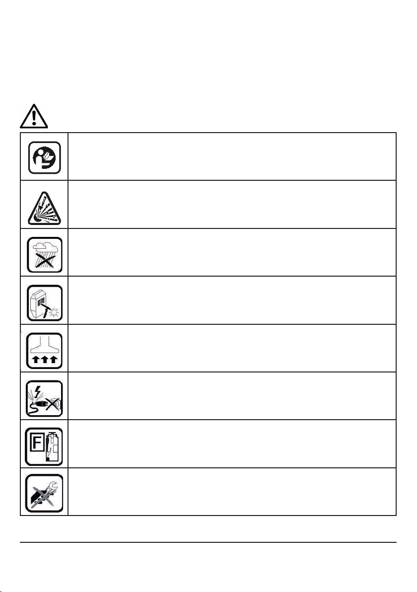
Attention!
Commissioning and normal operation are possible only after reading the carefully reading fol-
lowing manual. Arc welding requires compliance with the requirements for electric arc welding
and re regulations. The welder should be supplied with protective clothing and equipment in
accordance
with current regulations. It is necessary to use a set of personal protective equipment (PPE)
according to provisions of the Council Directive 89/686/EEC. The protection measures inclu-
des: welding mask with protective lter, welding gloves, apron, welding clothing, leather shoes.
Despite the high technical standard of the device, the personnel should represent considerable
discipline in approach to health and safety requirements to protect against harmful and health
hazardous factors developed from welding technology.
OPERATING CONDITIONS
This device can operate under severe conditions. It is however important to apply simple pre-
ventive measures to ensure long and reliable work:
- do not place or use this device on an inclined surface (of more than 15º),
- do not use the device for pipe defrosting,
- this device must be located within a free circulation, of clean air without restrictions of airow
to and from the fan, when the device is connected to electric network, do not cover it (with
paper or cloth)
- minimize the amount of dirt and dust that can get into the device,
- device housing has an IP21S protection. Keep it dry and do not place on wet surfaces
or in a puddle,
- do not use the device for welding the tanks previously used for storing ammable substances.
ENVIRONMENTAL CONDITIONS
Range of air temperatures for
- operation from -10ºC to +40ºC
- storage and transportation from -25ºC to +55ºC
- air relative humidity: up to 50% at +40ºC; to 90% at +20ºC.
GASES AND FUMES
TIG and MMA welding modes produce harmful gases and fumes containing ozone and hydro-
gen as well as oxides or metal particles. Therefore, the welding work station should be tted
with very good ventilation (dust and smoke extraction or airy location). Metal surfaces intended
for welding should be free from chemical contamination, especially degreasers (solvents) that
decompose during welding process and produce toxic gases. Welding of galvanized, cadmium-
-coated or chromium-plated parts is permitted only when a suction and ltering device is tted,
and with introduction of fresh air to the welding work station.

User Manual
Version 1.0 of 07.08.2019
Original manual
PONTIG 210 DC MOST -5-
RADIATION
Ultraviolet emission radiated when welding is harmful to eyesight and skin. Therefore a welding
mask with protective lters is required. Welding work station should meet certain requirements
and include:
- adequate lighting system,
- xed or movable protection screens, governing bystanders against radiation eects,
- placed in a room with appropriate wall colour (absorption of UV radiation)
FIRE PROTECTION
Welding work station should be located at a safe distance from ammables placed especially
on the oor or walls. All ammables need re protection against hot metal drops. It is
recommended to t the work station with re blankets and re extinguishers.
PROTECTION AGAINST ELECTRIC SHOCK
It is unacceptable to connect the device to an improper installation or to an installation
with unveried zeroing eciency. Removing the outer covers when
the device is connected to electric network, as well as using the device with removed covers.
IS PROHIBITED. It is not allowed to work on a suspended device e.g. using a gantry or a
crane. Maintenance and repair works should be carried out by authorized personnel
in compliance with the applicable safety conditions.
2. Maintenance
ATTENTION: In order to carry out any repair or maintenance activity, it is
recommended to contact your nearest technical support of RYWAL-RHC (a list of
authorized service shops is available on the last page of the manual).
In the event of noticing any damage, the welder should stop working, disconnect the device
from power supply and report it to direct supervisor or appropriate service - RYWAL-RHC
technical support.
General maintenance (daily)
- check the condition of cables and connections, replace if necessary,
- check condition of welding torch and connection with welding cable, replace if necessary,
- check condition and operation of the cooling fan; keep the cooling air inlet and outlet openings
clean,
- keep the device clean.
Periodic maintenance (at least every 3 months)
Periodic maintenance frequency can be increased depending on working conditions
and the intensity of use.
The scope of maintenance:
- using a stream of dry air (at low pressure) remove the dust from the outer parts of the casing
and from inside of the welding device,

User Manual
Version 1.0 of 07.08.2019
Original manual
PONTIG 210 DC MOST -6-
- check and tighten all the screws,
- check the state of all electrical contacts and repair if necessary.
WARNING: Device must be disconnected from electrical network before performing
any maintenance and service work. After each repair, perform respective
check to ensure safe use.
Mandatory device checks
According to the Labour Code provisions: „All responsibility for the safe use of machinery and
equipment shall be borne by the owner.” This results in the obligation to perform periodic and
post-repair checks and inspections of equipment.
Periodic tests are carried out at least once a year (legal basis EN ISO 17662 clause 4.2), and
post-repair tests after each repair that restored welding functionality (legal basis: EN 60974-4
clause 4.6).
All above services re performed by the technical support of RYWAL-RHC.
3. Technical description
The PONTIG 210 DC device is an inverter welding rectier for TIG welding in an argon shield
(arc ignition by HF ionizer) or an MMA coated electrode (Stick). The device has excellent we-
lding properties and has a wide range of applications. It may be used for welding:
a/ MMA electrode welding - direct current (DC) Recommended electrode diameter: 2.0 - 4.0
mm. Electrodes with a rutile or basic coating (open circuit voltage DC Uₒ = 65V), for steel and
stainless steel, b/ TIG DC method Arc ignition by an ionizer, automatically opened gas electro-
valve.
For stainless steel and steel welding a tungsten electrode is recommended with a diameter 1.6
or 2.4 mm, It is recommended to weld using continuous or pulsating current.
The device is protected against overheating by a thermal sensor. It is made in accordance with
the EN 60974-1 Standard, „Arc welding equipment. Part 1: Welding power
sources”.
4. Installation and use
- The user is responsible for connecting the device in accordance with the manufacturer
instructions. In the event of electromagnetic interference, the user should rectify the cause, if
necessary, with the knowledge of the manufacturer.
- Before using the device, the welder should estimate the possible impact of disturbances on
the environment, in particular the presence of persons with pacemakers or hearing aids.
- Work with a power generator is acceptable, but it must meet certain requirements. It is recom-
mended to use a unit with a power of min. 8 kVA with asynchronous generator. If the aggregate
does not provide adequate power, this results in lowering the arc parameters or turning o the
device.

User Manual
Version 1.0 of 07.08.2019
Original manual
PONTIG 210 DC MOST -7-
Parameter Unit Value
Electrical power supply V/Hz 1x230/50-60
Power tolerance % +15/-15
Welding current range A TIG: 10-200
MMA: 10-180
Welding current set point Smooth
Overload protection A 16 (delayed)
Work cycle
MMA DC A/%
180/35
137/60
106/100
Work cycle
TIG DC A/%
200/35
153/60
118/100
MMA electrode diameter mm 2,0-4,0
Sockets for connecting
welding cable
35/50 (large)
Power factor cos 0,7
Power consumption kW 8,2 (MMA)
6,0 (TIG)
Eciency % 85
Plug Schuko 16A
Insulation class F
Protection class IP 21S
Standard EN 60974-1
CE Ma
Dimensions mm 432x167x312
Weight kg 8,2
(11 kg carton of accessories)
Catalogue no. 52 00 005423
5. Technical data and device completion
Table 1: Technical data PONTIG 210 DC MOST.
Device assembly:
PONTIG 210 DC is delivered in a cardboard box with gas hoses,
mass cables and MMA welding electrode. TIG torch is an optional accessory - see Accessories.
Accessories:
TIG Torch 26 Most 4m(Pontig 210 /202) 56 01 032622
TIG Torch 26 Most 8m (Pontig 210/202) 56 01 032624
Welding trolley WUS HD 50 03 003942

User Manual
Version 1.0 of 07.08.2019
Original manual
PONTIG 210 DC MOST -8-
6. Device construction
Figure 1: PONTIG 210 DC MOST device construction
1. ON/OFF switch (rear side)
2. Gas connection (rear side)
3. Top handle
4. Control panel (see section 7)
5. Current socket (+)
6. TIG torch-controlled socket
7. TIG torch gas connection
8. Current socket (-)
9. Power cable with plug (device rear side)
8
9
2
1
7
3
6
5
4

User Manual
Version 1.0 of 07.08.2019
Original manual
PONTIG 210 DC MOST -9-
7. Pontig 210 DC Control panel
1. Parameter display
2. Parameter selection button
3. Operating mode selection button on the TIG torch
4. Welding parameter adjustment knob
5. Welding method selection button
Selection of welding method:
6. TIG pulse indicator
7. TIG DC indicator
8. MMA indicator
Selection of operation mode
from the TIG torch
9. 2T indicator (2-stroke mode)
10. 4T indicator (4-stroke mode)
11. Spot welding indicator

User Manual
Version 1.0 of 07.08.2019
Original manual
PONTIG 210 DC MOST -10-
12. I2 TIG background current indicator
13. I1 TIG/MMA welding current indicator
14. TIG current raise time indicator (upslope time)
15. TIG initial current indicator
16. TIG gas ow indicator
17. TIG pulse time factor indicator
18. TIG pulse frequency indicator
19. Spot welding time / HotStart arc ignition indicator
20. ArcForce function indicator
21. TIG gas post-ow indicator
22. TIG nal current indicator
23. TIG current drop time indicator (downslope time)
24. Thermal protection indicator
25. Output voltage indicator
Figure 2: Control panel and indicator description

User Manual
Version 1.0 of 07.08.2019
Original manual
PONTIG 210 DC MOST -11-
7.1. Description of the control panel operation:
- The control panel consists of keys, LED indicators, digital display and a knob. Control panel
operation is designed to be user friendly.
- The 3-digit display shows parameter settings, current values and error codes
E-x.
- Functions of the TIG 2T button operating mode are available; 4T and spot welding.
- TIG current rise time (upslope time), current drop time (downslope time), gas pre-ow time and
post-ow time are
adjustable.
- ArcForce function for MMA electrode welding: automatic increase of welding current
when the electrode is in contact with the material being welded, particularly useful at
welding pipes.
- Available with high-reliability TIG HF ignition.
- All functional parameters are adjustable.
- TIG DC, TIG pulse and MMA welding methods are available.
- Gas pre-ow time, post-ow time, initial current, current rise time (upslope time),
current drop (downslope time) and nal current are adjustable in the TIG DC method.
- Gas pre-ow time, post-ow time, initial current, time of current rise (upslope time),
current drop (downslope time), welding current, background current, pulse frequency are
adjustable
in TIG pulse method.
- Arc ignition time, pre-set current and arc current are adjustable.
- The device displays error codes (see chapter 10) in case of an overvoltage,
too low voltage or overheating.
- An error memory function and a statistical function are available, and able to provide cumulative
error times.
7.2 Saving parameters after welding.
The parameters used will be automatically saved after switching o the device (no auto-save will
be made if no operation is performed following setting of the parameters and if the machine is
switched o within 5 seconds).
When the device is switched on the next time, the last saved parameters will apply. When the
welding mode and the TIG button operating mode are selected again, auto-save will be carried
out after 10s. No special data memory key is available for this device.
7.3 Output voltage indicator
When the indicator no. 25 is on, voltage is on at the welding machine output sockets.
After selecting the TIG method, the output voltage will only be present when pressing
torch trigger (in 2T or 4T mode) and after a successful arc ignition.
After selecting the MMA method, the indicator no. 25 lights regardless the welding process on
or o.

User Manual
Version 1.0 of 07.08.2019
Original manual
PONTIG 210 DC MOST -12-
8. TIG DC welding method.
Connect the device to the 230 V mains by means of the no. 9cable .
Connect the TIG torch to the socket no. 8 (minus) on the front of the device, and control plug to
the socket no. 6and tighten the gas connection no. 7.
Insert the mass cable and secure it to socket 5 (plus), gas to connector 2 at the device back
side.
Turn on the device with the no. 1 ON/OFF switch.
A tungsten electrode with an respective diameter should be attached to TIG torch
also with sharpening angle adjusted to TIG welding current. See advices in table 2:
Material
thickness
[mm]
Tungsten
electrode
diameter
[mm]
Additional wire
diameter [mm]
Welding
current
[A]
Argon ow
[l/min]
Nozzle
outlet
[mm]
1 1 1,0 40-60 3 10
1,5 1,6 1,6 50-90 4 10
22,0 2,0 80-100 4 12
32,4 2,4 90-140 5 12
4-5 3,2 3,2 110-180 5 12
8.1 TIG DC welding (without pulsation)
Select the TIG DC method by pressing the welding method selection button 5 (indicator 7) and 2T mode
(indicator 9) by pressing the operating mode selection button 3.
Select the function for setting the gas pre-ow time (indicator 16 ) by pressing the welding parameter
selection button 2 and set the pre-ow time in counted in seconds with the knob no. 4(range 0.0-3.0s).
Table 2: Recommendations when welding stainless steel

User Manual
Version 1.0 of 07.08.2019
Original manual
PONTIG 210 DC MOST -13-
Select the initial current setting function (indicator 15 ) by pressing welding parameter selection button 2
and set the initial current in amperes using knob 4(range 10-200A).
Select TIG current ow rise time (upslope time) (indic. 14 ) by pressing the welding parameter selec-
tion button 2and set the upslope time in seconds with the knob 4(range 0-60s).
Select welding current settings I1 (indicator 13 ) by pressing the welding parameter selection button 2
and set the welding current in amperes using knob 4(range 10-200A).
Select the current descending time (range 0-60s) (indicator 23 ) by pressing welding parameter
selection button 2and set the descent time in seconds with knob 4(range 0-60s).

User Manual
Version 1.0 of 07.08.2019
Original manual
PONTIG 210 DC MOST -14-
Select the nal current settings (indicator 22 ) by pressing the welding parameter selection button 2
and set the nal current in amperes using knob 4(range 5-200A).
Adjust the gas post-ow time (indicator 21) by pressing the welding parameter selection
button 2 and set the ow time in seconds with knob 4 (range 0-20s).
Table 3: Functions available for TIG DC welding
After setting welding parameters, adjust the correct argon ow with the bottle reducer.
Press the TIG torch button to start the solenoid valve and the HF ionizer.
TIG torch should be kept 2 ~ 4 mm from the workpiece. After the arc is ignited, the HF current disappears
and the current welding I1 increases to the previously set value. After releasing the torch button, the current
starts automatically reduce to the previously set nal current value. Then the arc goes out while maintaining
the gas ow at the set time of post-ow.

User Manual
Version 1.0 of 07.08.2019
Original manual
PONTIG 210 DC MOST -15-
8.2 TIG Pulse welding
Select the TIG current pulse (indicator 6) by pressing the welding mode selection key 5and the 2T mode
by pressing the operating mode selection button 3.
Select the function for setting the gas pre-ow time (indicator 16) by pressing the welding parameter
selection button 2 and set the pre-ow time in seconds with the knob no. 4(range 0.0-3.0s).
Select the initial current setting function (indicator 15 ) by pressing the welding parameter
selection button 2and set the initial current in amperes using knob 4(range 10-200A).
Select TIG current ow rise time (upslope time) (indic. 14 ) by pressing the welding para-
meter selection button 2and set the rise time in seconds with the knob 4(range 0-60s).

User Manual
Version 1.0 of 07.08.2019
Original manual
PONTIG 210 DC MOST -16-
Select welding current settings I1 (indicator13 ) by pressing the welding parameter selection button 2
and set the welding current in amperes using knob 4(range 10-200A).
Select the background current settings I2 (display 12) by pressing the welding parameter selection
button 2and set the background current in amperes using knob 4(range 10-200A).
Select TIG current descending time (downslope time) (indic. 23 ) by pressing the welding parameter
selection button 2and set the downslope time in seconds with knob 4(range 0-60s).
Select the nal current setting function (indicator 22 ) by pressing the welding parameter selection
button 2 and set the nal current in amperes using knob 4(range 5-200A).

User Manual
Version 1.0 of 07.08.2019
Original manual
PONTIG 210 DC MOST -17-
Adjust gas post-ow time (indicator 21 ) by pressing the welding parameter selection button 2and set
the time of post-ow in seconds with the knob 4(range 0-20s).
Select TIG pulse time factor (indicator 17) by pressing the welding parameter selection button 2 and
adjust the duration of the current value I1 to I2 in percent using knob 4(range 10-90%).
Select the TIG pulse frequency setting function (indicator 18 ) pressing the welding parameter
selection button 2and set the frequency in Hz with knob 4(range: 0.5-200Hz).
Table 4: Functions available for TIG pulse welding.
After setting welding parameters, adjust the correct argon ow with the bottle reducer.
Press the TIG torch button to start the solenoid valve and the HF ionizer.
TIG torch should be kept 2 ~ 4 mm from the workpiece. After the arc is ignited, the HF current disappears
and the current welding increases to the previously set value. The current is pulsing in the range from I1 to
I2, according to the set parameters 17 and 18 After releasing the torch button, the current begins to automati-
cally decrease to the nal arc value. Then the arc goes out while maintaining the gas ow at the set up time.

User Manual
Version 1.0 of 07.08.2019
Original manual
PONTIG 210 DC MOST -18-
8.3 Operating mode available on the TIG torch trigger
Mode 3 is available in TIG pulse and TIG DC mode and includes 2T, 4T and spot welding.
Select the 2T mode (indicator 9 ) by pressing the operating mode selection button 3. Operations in 2T
mode (2-stroke): Press the torch trigger, the gas valve opens and starts high frequency HF arc ignition.
Hold the torch at a distance of 2 ~ 4 mm from the workpiece. After the arc is ignited, HF turns o and the
welding current increases to the set value. Release the torch trigger and the current will decrease
to the value of the nal arc and then turn o. The gas will still ow according to the set up post-ow.
Select the 4T mode (indicator 10 ) by pressing the operating mode selection button 3.
Operations in 4T mode (4-stroke): Press the torch trigger, the gas valve opens and starts high
frequency HF arc ignition. Keep the torch 2 ~ 4 mm away from the workpiece. After the arc is ignited,
HF turns o and the welding current increases. Release the torch trigger,welding will continue with the
set value of I1 current. Press the torch trigger again and release it, and the current value will fall to
the value of the nal arc and then turn o. Gas will still ow according to the set up gas post-ow.
Select the spot welding mode (indicator 11 ) by pressing the operating mode selection button 3.
Set the spot welding time value(indicator 19 ) in seconds with knob 4 (range 0.1-10s).
Table 5: TIG welding and operation modes available on the torch trigger
Operations in spot welding: Press the torch trigger, the gas valve opens and the high frequency HF arc igni-
tes. The torch should be kept 2 ~ 4 mm from the workpiece. After the arc ignites, the HF arc goes out and
the current increases to the set value I1. Welding lasts according to the set time, the trigger does not have
to be released to complete the task. In spot welding mode, current value does not change.

User Manual
Version 1.0 of 07.08.2019
Original manual
PONTIG 210 DC MOST -19-
9. MMA coated electrode welding
Connect the device to the 230 V mains using cable 9 (Fig. 1).
Connecting the wires to the MMA electrode welding
- Connect the ground wire plug to the 8 (-) socket on the device
- Connect the plug of the electrode holder to socket 5 (+) on the device.
ATTENTION: Some coated electrodes require reverse polarity - see instructions
on the electrode packet. Switch on the unit with 1 ON / OFF switch.
Starting the welding mode with the electrode is carried out by pressing button 5 -
indicator 8 lights up (See chapter 7 - Fig. 2).
ATTENTION: Avoid accidentally touching the end of the electrode with the workpiece,
as the welding current is still present in the cables. After switching the device on (ON),
set the proper welding current for the given electrode diameter with the knob (1) (see
instructions on the electrode packet). The value of the welding current is shown in
display 1 (the indicator 25 lights up continuously).
The electric arc is initiated by rubbing the end of the electrode with the base material (connected
with the device by earth cable), and after the arc occurs, it is necessary to quickly move
the tip to a certain distance.
If the tip of the electrode is removed too quickly, the arc will be torn o and alternatively, moving
too slow can result in creating short circuit and sticking the end of the electrode to the material.
Select MMA welding (indicator 8 ) by pressing the welding mode selection button 5. There is no-load
voltage at both output terminals (ground clamp and electrode holder).
In the MMA welding mode, the voltage indicator 25 is permanently on.
Select the welding current setting 13 by pressing the welding parameter selection button 2 and adjust
welding current for the MMA using knob 4 . Welding current may be changed during welding work.

User Manual
Version 1.0 of 07.08.2019
Original manual
PONTIG 210 DC MOST -20-
Select the function of setting the arc ignition time 19 by pressing the welding parameter selection button
2 and set the time for the arc ignition for MMA method (range for HotStart- 0,1-1,0s).
Select the ArcForce 20 function by pressing the welding parameter selection button 2 , and then set the
arc current for MMA. The value of ARCFORCE can be changed during welding(range 0-180).
Table 6: MMA welding and available functions.
Table of contents
Other Most Welding System manuals

Most
Most Fanmig J5 MOST User manual

Most
Most PONTIG 202 AC/DC MOST User manual

Most
Most MasterCut 120 CNC User manual

Most
Most PONTE 201 PRO MOST User manual

Most
Most Fanmig 201 LCD User manual

Most
Most Fanmig 322 mobil Pulse User manual

Most
Most Fanmig 522i Pulse User manual

Most
Most FANMIG 280-4N Minor User manual
Popular Welding System manuals by other brands

Miller Electric
Miller Electric SubArc owner's manual

Lincoln Electric
Lincoln Electric US-CW223 datasheet

Hobart Welding Products
Hobart Welding Products Handler 125 owner's manual

Miller
Miller Continuum 500 owner's manual

STAMOS
STAMOS S-MMA-120PI user manual

Lincoln Electric
Lincoln Electric REDI-MIG 255 Integrated operating manual