Mostec M2118 User manual

Operating Manual
AlarmUnit
Type M2118
Mostec AG
Mess-und Regeltechnik
Lausenerstrasse13a
CH-4410 Liestal, Switzerland
Tel.+41 61 921 40 90
Fax+41 61 921 40 83
Internetwww.mostec.ch
E-Mail info@mostec.ch

M2118 Operating Manual
V1.06
©
17.10.2011
MOSTEC
AG
, CH
-
4410 Liestal
2
Warranty
Mostec warrantsthisproducttobe free ofmanufacturingdefectsfora2-yearperiod afterthe original
dateofpurchase.Withinthisperiod,defectiveproductswill be repaired free ofchargeprovided thatthe
defectoccurred duringnormaloperation.Thiswarrantydoes notcoverdamagetothe productresulting
fromordinaryusagesuch as frontpanelscratches,broken controlelementsand corrosion,etc.The
customerisresponsibleforshippingand packingcharges forproductsreturned underwarrantyto
Mostec.Mostec warrantsthisproductbeyond the 2-yearwarrantyperiod foran additional2yearsin
case oflongterm damages due toimpropermanufacturing.Such damages as poorlysoldered jointsor
otherassemblyproblemsarealso covered bythe warranty.Transportation damages arenotcovered by
the warrantyand shouldbe referred tothe respectivedeliveryservice.
Technical description
The alarm unitM2118 isused tocheckorcontrolanytype ofsignalcurrentorvoltagesignal.It converts
the inputsignaltoan internalstandardsignalofforexample0to100.0%.Inthisrangetwoalarm
contactscan be setindependently.A4-digitLED displayshowsthe actualvalue and setpointsoralarm
values inthe rangeof-1999 to9999 units.
All settingsas alarm values,hysteresis,rangeand operatingmode ofthe floatingcontactscan be set
withalinkcable, connected toapersonalcomputer or alaptop.
Bothalarm contactscan also be programmed withtinypush button switches behind the front panel.
Atypicalapplication wouldbe tomeasureand monitorpressureinaprocess vessel.The pressure
transmitterconvertsthe pressureof1to10 bartoacurrentsignalof4to.20mA.The M2118 monitors
under- and overpressureinthe vessel.It convertsthe 4... 20mAsignalcurrentto0...100.0%.The alarm
issetbetween 0%(=1bar) and 100.0%(=10 bar). Withthese floatingalarm contacts,overpressure
valves, compressors, etc. aredriven directly.
Optionally, agalvanicisolated output signalof0...20mAor 4...20mAisavailable.
Power supply: Universalsupply20 to253VAC/DC

M2118 Operating Manual
V1.06
©
17.10.2011
MOSTEC
AG
, CH
-
4410 Liestal
3
Index: Page
AFront panelcontrols3
BAdjusting the limit contactswith two programming buttons/ handling access codes3/4
C Adjusting the limit contactswith programming software 4
D Adjusting the displayrange with programming software 4
EAdjusting a tare value 5
FAdjusting the output signalrange with programming software 5
GFine-adjust the display/current output with the programming buttons6
H Fine-adjust the displaywith programming software 6
I Generalreferencesforusing the programming software 6
JTechnicaldata 7
KUsermenu 8
A.Font panel controls
B. Adjusting thelimit contactswithtwoprogramming buttons
The value ofthe limit contactscan be changed bytwobuttons without programmingSoftware.
1. Unlock the usermenu / insertormodifythe menu protection access code:
The valuesofthe usermenu can be protected fromunintended access using an access code. Afteractivating the
access code, menu valuescan be observed but no longermodified. To modifysetpointsand otherparameters, the
access code hasto be set to the value 0000. Ifthe code hasa value different from0000, writing to the usermenu is
suppressed.
Set the access code:
1. Press and hold both buttons<ENTER>und <ESC>for4 seconds.
ðAfter4 secondsThe displayshowsSP_1 indicating the usermenu.
2. Nownavigate to the Code menu itemwith the button <->, then press <ENTER>.
a)Acode hasalreadybeen entered: The displayflashesbetween Code und 0. Enternowthe valid access
code with the buttons<+> and <->and confirmwith the <ENTER>key. Ifthe code iswrong, the instrument
quitsthe usermenu (in case you do not knowyourcode anymore, call MOSTEC we have a unlockcode). If
the code iscorrect, it can be modified with the keys<+> and <->, orin orderto make changesto the user
menu, set to 0000.
b)No code hasbeen entered: The displayshows0000. Acode can be entered with the keys<+> and <->
then confirmwith the <ENTER>key. Ifyou do not need the usermenu protection, leave the value 0000
unchanged and quit the code menu with the <ESC>key.
progamming adapter
<+> / SP1
<->/ SP2
ESC /Temp
ENTER / Setup

M2118 Operating Manual
V1.06
©
17.10.2011
MOSTEC
AG
, CH
-
4410 Liestal
4
2.Adjustthe limitcontacts:
1. Push and hold the button <ENTER>for4 seconds.
ðThe displaywill showup the programmenu.
2. Change to menu SP_1 forlimit contact #1 orSP_2 forlimit contact #2,
bythe button <+> or<->, then press <ENTER>.
ðThe displayshowsthe actualvalue ofthe limit contact.
3. Change the value forthe limit contact bythe button <+> or<->, then press <ENTER>.
4. Change to menu HSt_1 forlimit contact #1 orHSt_2 forlimit contact #2,
bythe button <+> or<->, then press <ENTER>.
5. Change the value forthe hysteresisbythe button <+> or<->, then press <ENTER>.
6. Change to menu LEd_1 forlimit contact #1 orLEd_2 forlimit contact #2,
bythe button <+> or<->, then press <ENTER>.
7. Change the lamp status bythe button <+> or<->, then press <ENTER>.
"nor":LED lamp ON, when input >setpoint
"Inr":LED lamp ON, when input <setpoint
8. Change to menu rEL_1 forlimit contact #1 orrEL_2 forlimit contact #2,
bythe button <+> or<->, then press <ENTER>.
9. Change relayoperating mode bythe button <+> or<->, then press <ENTER>.
"nor":RelayON, when input >setpoint (normalmode)
"Inr":RelayON, when input <setpoint (fail-safe mode)
10.Press button <ESC>
ðthe displayshowsthe actualvalue.
C. Adjusting thelimit contactswithprogramming software
Connect the link cablewithAdapter tothe Computer and the display. (see I, page 6)
1. start "Mpro"
2. Choose "M2118" inmenu "Instrument" <A>
3. Choose "Linear conversion table" under "Range" <B>
4. Choose "Adjust the limit contacts" <C>
5. Enter the values for the limit contactsand all other settings(hysteresisetc.)
6. Choose "Program the limit contacts"
D. Adjusting thedisplayrangewithprogramming software
Connect the link cablewithAdapter tothe Computer and the display. (see I, page 6)
1. start "Mpro"
2. Choose "M2118" under "Instrument" <A>
3. Choose "Linear conversion table" under "Range" <B>
4. Enter the value for input range, output rangeand decimalplace
5. Choose "Program"

M2118 Operating Manual
V1.06
©
17.10.2011
MOSTEC
AG
, CH
-
4410 Liestal
5
E. Adjusting atarevalue
Note: The measuring range isreduced bythe set tare!
1. Adjusting a tare value with the programming buttons
1. Press and hold the button <ENTER>and <+>.
ðThe displayshows tarE and the actualmeasuring value, after3 secondstare isadjusted.
ðThe displayshowsthe actualmeasuring value.
2. Switchoff tare with the programming buttons
1. Press and hold the button <ENTER>and <+>.
ðThe displayshows tarE and the actualmeasuring value, after3 secondstare isswitched off.
ðThe displayshowsthe actualmeasuring value.
3. Adjusting a tare value with the menu
1. Press and hold the button <ENTER>and <ESC>for4 seconds..
ðThe displayshows SP_1 indicating the usermenu.
2. Move to menu itemTARE. To move, use the button <+> or<->, then press <ENTER>.
3. Switch on orswitch off tare. To move, use the button <+> or<->, then press <ENTER>.
4. Press the button <ESC>
ðthe displayshowsthe actualmeasuring value.
F. Adjusting theoutput signal rangewithprogramming software
Connect the link cablewiththe Computer and the display. (see I, page 6)
1. start "Mpro"
2. Choose "M2118" inmenu "Instrument" <A>
3. Choose "Linear conversion table" under "Range" <B>
4. Choose "Adjust the output signal" <D>
5. Enter the values for the limit contactsand all other settings(hysteresisetc.)
6. Choose "Program the limit contacts"
<A>
<B>
<C>
<D>

M2118 Operating Manual
V1.06
©
17.10.2011
MOSTEC
AG
, CH
-
4410 Liestal
6
G. Fine-adjust thedisplay/current output withthe programming buttons
The displayand the current output can be changed without programming Software and PC.
1. Unlock the usermenu / insertormodifythe menu protection access code:
see B, page 3
2. Adjustthe limitcontacts:
1. Press and hold the button <ENTER>for4 seconds.
ðThe displayshows SP_1 indicating the usermenu.
2. Move to menu itemd_Zo fordisplaymin. and ord_GAfordisplaymax. value,
orI_Zo forcurrent output min. and I_GAforcurrent output max. value
To move, use the button <+> or<->, then press <ENTER>.
ðThe displayindicatesthe actualvalue ofthe limit contact.
3. Change the value, using the button <+> or<->, then press <ENTER>.
4. Press the button <ESC>
ðthe displayshowsthe actualmeasuring value.
H. Fine-adjust thedisplaywithprogramming software
Connect the linkcable with adapterto the computerand the display. (see I, page 6)
1. start "Mpro"
2. Choose "M2118"in menu "Instrument"<A>
3. Choose "Adjust"forfine-adjusting the "Gain"or"Zero"<B>.
I. General references forusing theprogramming software
-The newest software maybe downloaded anytime and free ofchange at www.mostec.ch.
-Connect the M2118 to the powersupplyforprogramming
-Be sure that the connected COM-port isn`t used byanyotherperipherialdevice.
-Ifthe PC orthe corresponding COM-port is"grounded"bythe powerline cable orbyothercabeling, ground
loopsmayinterfere with the measuring signal. The use ofa computerwith batterypowerisrecommended to
avoid such problems.
-Contact usifthere are problemsorquestionsconcerning the software.
Non-liability
The companyMostecAGdeveloped and tested the software "Mpro"with largest care. Mostecisnot responsible for
anydamageswhatsoever, including loss ofinformation, interruption ofbusiness, personalinjuryand/oranydamage
orconsequentialdamage without limitation, incurred before, during orafterthe use ofourproducts.
<B
<A

M2118 Operating Manual
V1.06
©
17.10.2011
MOSTEC
AG
, CH
-
4410 Liestal
7
J. Technical Data
Inputsignal:
Terminals:3x6-pole
Weight:200g
Warranty:2years
Options:
Inputload/impedance:currentsignal=51,voltage signal=1M
2-Wiretransmittersupply
Reproducibility
Temperaturecoefficienterodrift:30ppM/°C typical
aindrift:25ppM/°Ctypical
Long-termstability
Workingtemperaturerange:-5to+45°C
Maximumhumidity:95%,non-condensing
wo,adjustablebetween0,0and100,0%
loatingchange overcontacts
:1A/230Vresistive
Powersupply:Wat230VAC
CE-conformity:fulfilled plug-inscrewterminals
Terminaldescription:1
c.o.=change overalarmcontact 1,c.o.contact8=alarmcontact1,n.c.contact
n.o.=normallyopen9=alarmcontact 1,n.o.contactalarmcontact1,c.o.contact
d.c.=normallyclosed11=alarmcontact 2,n.c.contact12=alarmcontact2,n.o.contact
13=signalinputPE14=signalinput(-)
15=signalinputcurrent(+)16=signalinputvoltage(+)
17=2-Wiretransmittersupply+24V2-Wiretransmittersupply
Case:DIN-standard71mm,snap-on toDIN46277rails
WW
0/4...20mA/0...1Vand10V,programmable
:24VDCmax.25mA
Display:
Accuracy:23°Cambienttemperature
: :z
:
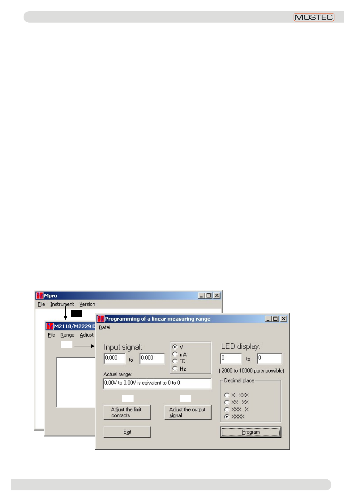
Range adjustment:bycomputer programmable,see manual
Zero-/Gainadjustment:bycomputer programmable,see manual
Alarmcontacts:t
Hysteresis:bycomputer programmable,factoryset:seemanual
Contacts:f
Changealarmcontacts:bybuttonswitchesorcomputerprogrammable,seemanual
Displayalarmcontacts:bybuttonswitchesorcomputerprogrammable,seemanual
Mode ofthealarmcontacts:withtwored
Displayunit:withonered
Option currentoutput:0/4...20mA,galvanicallyisolated
Max.load:500
Outputimpedance:>1Mtypical
20 to253VACorDC
Powersupplyload:4.5to7.0
=supplyvoltage: AC~/DC(+)2=supplyvoltage:AC~/DC(-)
3=supplyvoltage:PE4=signaloutputPE
5=signaloutput(+)6=signaloutput(-)
7= 10=
18=PE
-Linkcableforprogramming withacomputer:P/NM2029LAP
-Programming software(free download:www.mostec.ch)
-Otherinputsignal
Howtoorder:M2118,input4...20mA,display 50...100,0%,
SP1=2,00bar,PS2=9,50bar,Hysteresis
W
W
4-digit,LEDred,10mm
Displayrange:-1999...9999
±0.1%at
±0.1% ,
g
±0.1%
±5digit,
Max.contactload
LED-Lamps
LED-Lamp
±2digit,
currentoutput:50...100,0%=0...20mA
Pressurecontrol:
Dimensions (mm):
PI
Transmitter
PI
®
Analog instrument,
recorder,orprocess
computer
M2118
%
Supply
SP195%
tooverpressure
valve
SP210%
topump
·
·
·
·
·
·
Output
(SP=Setpoint)

M2118 Operating Manual
V1.06
©
17.10.2011
MOSTEC
AG
, CH
-
4410 Liestal
8
K. Usermenu
Menu access:press the button (ENT) for 4seconds.
Navigation withinthe menu:buttons (+) and (-)
Select amenu item: button (ENT) (= ENTER)
Leaveamenu item: button (ESC) (= ESCAPE)
Changeavalue:buttons (+) and (-)
(ENT)
â
àSP_1 (ENT)à(+)/(-)Adjust setpoint 1
ß(ESC)/(ENT)1.053
** *
â(+)/ á(-)
àHSt1 (ENT)à(+)/(-)Adjust hysteresis1
ß(ESC)/(ENT)0.007
â(+)/ á(-)
àLED1 (ENT)à(+)/(-)LED 1 function normal/inverse
ß(ESC)/(ENT)NOR /INR
â(+)/ á(-)
àREL1 (ENT)à(+)/(-)Relay1 function normal/inverse
ß(ESC)/(ENT)NOR /INR
â(+)/ á(-)
àSP_2 (ENT)à(+)/(-)Adjust setpoint 2
ß(ESC)/(ENT)1.053
â(+)/ á(-)
àHSt2 (ENT)à(+)/(-)Adjust hysteresis2
ß(ESC)/(ENT)0.007
â(+)/ á(-)
àLED2 (ENT)à(+)/(-)LED 1 function normal/inverse
ß(ESC)/(ENT)NOR /INR
â(+)/ á(-)
àREL2 (ENT)à(+)/(-)Relay1 function normal/inverse
ß(ESC)/(ENT)NOR /INR
â(+)/ á(-)
àCode (ENT)à(+)/(-)Change menu access code
ß(ESC)/(ENT)0036
â(+)/ á(-)
àd_2o(ENT)à(+)/(-)Fine-adjust displaymin. value
ß(ESC)/(ENT)0000
â(+)/ á(-)
àd_GA (ENT)à(+)/(-)Fine-adjust displaymax. value
ß(ESC)/(ENT)0000
â(+)/ á(-)
ài_2o(ENT)à(+)/(-)Fine-adjust current output min. value
ß(ESC)/(ENT)0000
â(+)/ á(-)
àI_GA (ENT)à(+)/(-)Fine-adjust current output max. value
ß (ESC)/(ENT)0000
â(+)/ á(-)
àtARe (ENT)à(+)/(-)Adjust tare
ß(ESC)/(ENT)on /off
** Leave the menu without saving the value
*Leave the menu and save the value
Table of contents