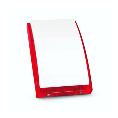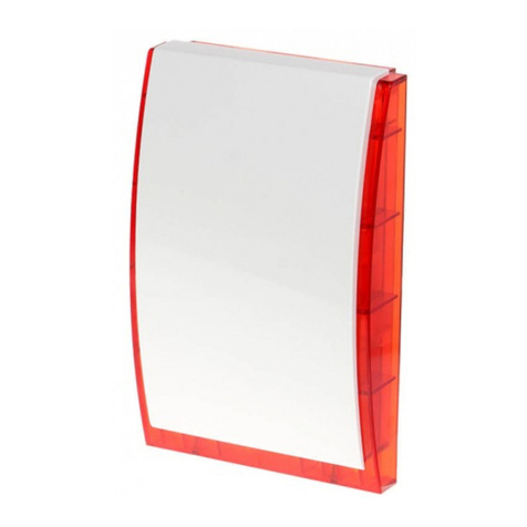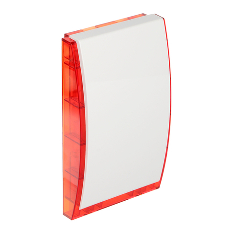
SATEL ABAX 3
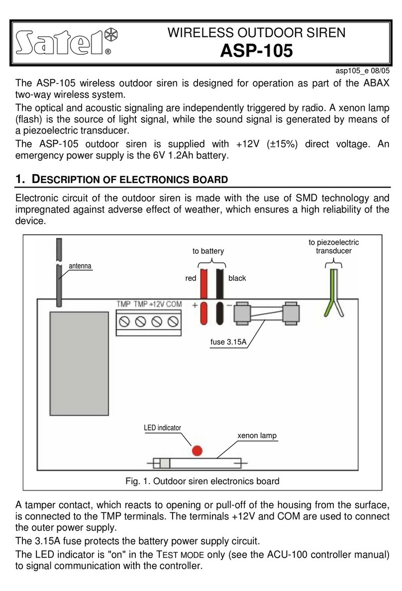
red LED. When in the test mode, it indicates the siren polling (short flash).
optical signaling LEDs (two LEDs are installed in the ASP-105 BL siren).
2. I
NSTALLATION
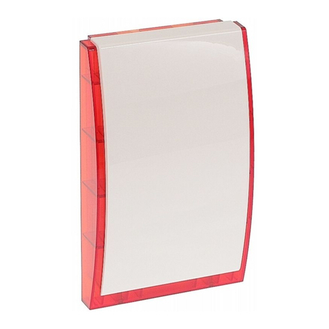
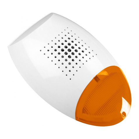
The ASP-105 outdoor siren should be mounted on the wall, at a high and hard-to-access
place, so as to minimize the risk of tamper. Maintain an adequate distance (minimum 2.5 cm)
between the top edge of the siren enclosure and the ceiling or another element situated
above the siren. Replacement of the cover may turn out to be impossible due to the lack of
space.
1. Remove the enclosure cover.
2. Connect the battery to corresponding leads.
3. Add the siren to the wireless system (see the ACU-100 controller manual,
INTEGRA 128-WRL or VERSA control panel installer manual) and close the cover.
4. Select the place where the siren is to be installed, and mount the device there
temporarily.
5. Check the level of signal received from the siren. If necessary, select another place for
installation, to ensure adequate communication quality.
6. Having found the place which ensures the optimum signal level, remove the cover and
disconnect the battery.
7. Mark on the mounting surface the location of the holes for enclosure base fixing screws
and tamper switch, as well as the opening through which power wires will be run.
8. Drill the corresponding holes in the mounting surface.
9. Pull the 12 V DC power wires through the opening in the base.
10.Using wall plugs (screw anchors) and screws, fasten the enclosure base and tamper
switch to the mounting surface.
11.Connect the backup battery.
12.Connect the supply wires to the electronics board terminals. The wires should not be run
in the immediate vicinity of the siren antenna, because it may interfere with the radio
communication.
13.Close the cover and secure it with screws.
14.Turn on 12 V DC power.
15.Configure the siren operating parameters (e.g. select one of the four tone types and
determine maximum duration of sound signaling). Detailed information relating to the
configuration can be found in the ACU-100 controller manual and the INTEGRA and
VERSA control panel programming manuals.
3. S
PECIFICATIONS
Operating frequency band ....................................................................868.0MHz ÷ 868.6 MHz
Radio communication range (in open area)............................................................ up to 500 m
Supply voltage ................................................................................................... 12 V DC ±15%
Backup lead-acid battery .......................................................................................... 6 V/1,2 Ah
Standby current consumption (with fully charged battery) ...............................................30 mA
Maximum current consumption (with fully charged battery):
optical signaling......................................................................................80 mA
acoustic signaling .................................................................................225 mA
