motogadget m-stop User manual

by motogadget
Bedienungsanleitung m-Stop
Haftungsausschluss
DAS GEHÄUSE DARF NICHT GEÖFFNET WERDEN. IN DIESEM FALLE ERLISCHT JEDER GEWÄHRLEISTUNGSANSPRUCH.
BEI VERWENDUNG DES GERÄTES FÜR EINEM NICHT VORGESEHENEN VERWENDUNGSZWECK (SIEHE KAPITEL ANWENDUNGS-
BEREICH) ERLÖSCHEN SÄMTLICHE GARANTIEANSPRÜCHE. MOTOGADGET ÜBERNIMMT KEINERLEI HAFTUNG FÜR DIREKTE
ODER INDIREKTE SCHÄDEN ODER FOLGESCHÄDEN ALLER ART, DIE DURCH DIE VERWENDUNG, DEN ANBAU ODER DEN
ANSCHLUSS DES GERÄTES ODER DES MITGELIEFERTEN ZUBEHÖRS ENTSTEHEN. DARUNTER FALLEN UNTER ANDEREM ALLE
SCHÄDEN AN PERSONEN, SACHSCHÄDEN UND FINANZIELLE SCHÄDEN. SPEZIELL DIE VERWENDUNG IM BEREICH DES
ÖFFENTLICHEN STRAßENVERKEHRS ERFOLGT AUF EIGENE GEFAHR.
Anwendungsbereich
Der m-Stop ist ein elektronischer Schalter. Das Gerät kann ausschließlich resistive Lasten (Glühlampen oder LED) bis zu einer
Maximalstromstärke von 7A schalten. Die Maximalbelastung entspricht 4 Glühbirnen a 21W. Das Gerät ist nicht geeignet um kapazitive Lasten
(z.B. Hupe) oder induktive Lasten (z.B. Spulen, Relais) zu schalten. Die Umgebungstemperatur darf im Betrieb -20° nicht unterschreiten und +85°
nicht überschreiten. Bei der Verwendung von LED Lampen sind während der Dauerleuchtphase in Modus 1 und 4 in regelmäßigen Abständen
kurze Dunkelphasen (ca. 4 Millisekunden) sichtbar. Diese Dunkelphasen sind technisch bedingt und lassen sich nicht vermeiden. Bei Modus 4
und 6 benötigt das Gerät nach dem Abschalten eine Pause von 4 s um den Schaltzyklus wieder von vorn zu beginnen. Wird diese Pause nicht
eingehalten, wird der Verbraucher mit dem gleichen Schaltmuster wieder eingeschaltet wie unmittelbar nach dem ausschalten.
Batterie und Spannungsversorgung
Der m-Stop arbeitet mit Spannungen von 5,5V bis 18V Gleichspannung und ist für 6V und 12V Bordnetze geeignet. Der Betrieb an Fahrzeugen
ohne Batterie im Bordnetz ist nicht vorgesehen und wird nicht empfohlen. Das Gerät schaltet nicht bei einer Spannung unterhalb 5,5V. Eine
Spannung über 18V zerstört das Gerät. Auch ein direkter Kurzschluss ohne Last zerstört das Gerät. Nehmen Sie das Gerät nicht in Betrieb wenn
keine einwandfreie Funktion gewährleistet ist (bei Dauerleuchten). Jedes LED Rücklicht ist intern anders geschaltet. Sollte Ihr Rücklicht mit dieser
Anleitung nicht wunschgemäß funktionieren, finden sie Hilfe unter „Support“ auf www.motogadget.de.
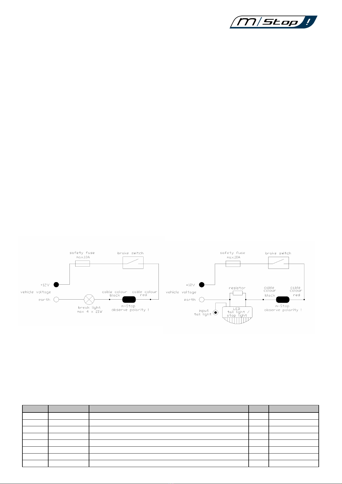
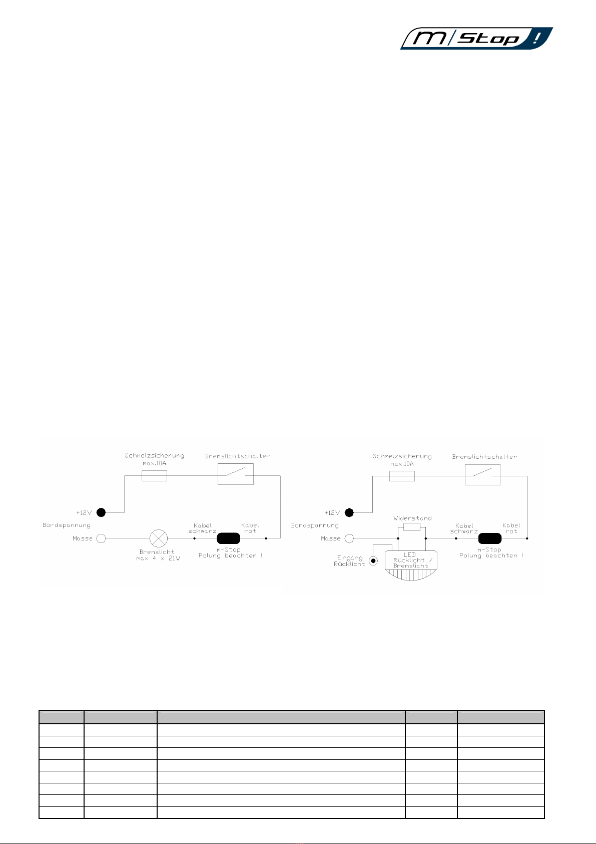
Polung
Achten Sie bei der Montage unbedingt auf die richtige Polung der Versorgungsspannung.
Rotes Kabel = Richtung +12V, schwarzes Kabel = Richtung Masse. Eine kurzeitige Verpolung (<5s) führt zu keiner Beschädigung, in diesem Fall
leuchten die angeschlossenen Verbraucher dauerhaft und blinken nicht. Eine Verpolung länger als 5s zerstört das Gerät.
Trennen sie die Leitung an der Montagestelle und prüfen sie die Polarität beider Enden mit einem Voltmeter.
Kommt das Gerät an einer LED Rücklicht/Bremslichteinheit zur Anwendung, muss der mitgelieferte Hilfswiderstand parallel zwischen
Bremslichteingang und Masse geschaltet werden.
ACHTUNG!
Der zu verwendende Mindestquerschnitt des Anschlusskabels beträgt 0,75 mm². Der Stromkreis muss mit einer 10A
Schmelzsicherung abgesichert werden. Wird keine Sicherung verwendet, kann es bei Beschädigung der Anschlusskabels oder des
Gerätes zu einem Kurzschluss und einem Kabelbrand kommen. Es besteht Lebensgefahr! Führen Sie den elektrischen Anschluss
sachgerecht aus! Wenn Sie nicht über die nötige Sachkenntnis verfügen, lassen Sie den Anschluss von einer Fachwerkstatt
durchführen.
Montage
Achten Sie bei der Auswahl des Montageortes des Gerätes auf folgende Punke:
•wassergeschützte Stelle
•ausreichender Abstand von heißen Motor/Auspuffteilen (max. Temperatur im Betrieb 85°C)
•mindestens 30cm entfernt von elektromagnetischen Störquellen wie Zündspulen und Zündkabeln.
Wichtig ist eine ausreichende Zugentlastung und Knickschutz der Anschlusskabel. An mechanisch beanspruchten Stellen muss eine zusätzliche
Ummantelung verwendet werden um eine Beschädigung der Kabelisolation zu verhindern. Es dürfen keine mechanischen Belastungen auf das
Gerät einwirken (Zug-, Druck-, Stoßbelastungen). Das Gerät kann mit Kabelbindern direkt am Kabelbaum „fliegend“ installiert werden.
Entfernen Sie vor der Montage die Fahrzeugbatterie oder unterbrechen Sie die Verbindung zum Bordnetz. Verwenden Sie einen
Fahrzeugschaltplan. Führen Sie den elektrischen Anschluss sachgerecht aus.
Bedienung
Der m-Stop bietet 8 verschiedene Einstellmöglichkeiten. Diese werden mit dem DIP – Schalter wie folgt eingestellt:
Funktion Schalterstellung Blinkmuster Glühlampe LED
Modus 1 ON/ON/ON Dauerleuchten ja ja, mit Lastwiderstand
Modus 2 ON/ON/OFF Auf und Abschwellen mit 3 Hz ja ja, mit Lastwiderstand
Modus 3 ON/OFF/ON Blinken mit 5 Hz ja ja, mit Lastwiderstand
Modus 4 ON/OFF/OFF 8 mal blinken mit 5 Hz dann Dauerleuchten ja ja, mit Lastwiderstand
Modus 5 OFF/ON/ON 2 mal Blinken mit 5 Hz dann 1s Dauerleuchten und wieder von vorn ja ja, mit Lastwiderstand
Modus 6 OFF/ON/OFF m-wave, weiches Blinken ja ja, mit Lastwiderstand
Modus 7 OFF/OFF/ON Blinkrelais mit automatischer Abschaltung nach 20 Sekunden ja ja, mit Lastwiderstand
Modus 8 OFF/OFF/OFF Blinkrelais ja ja, mit Lastwiderstand

by motogadget
Instruction manual m-stop
Exclusion of liability
DEVICE HOUSINGS AND ALL OTHER DELIVERED PARTS MUST NOT BE OPENED OR DISMANTLED. IN CASE OF NON-COMPLIANCE
ALL GUARANTEE CLAIMS BECOME INVALID. MOTOGADGET ACCEPTS NO LIABILITY FOR DIRECT OR INDIRECT DAMAGE OR
SUBSEQUENT DAMAGE OF ANY KIND RESULTING FROM THE USE, INSTALLATION OR CONNECTION OF THE M-STOP OR OTHER
DELIVERED EQUIPMENT. THIS EXCLUSION OF LIABILITY PARTICULARLY INCLUDES DAMAGE TO PERSONS, MATERIAL LOSSES
AND FINANCIAL DAMAGES. THE USE OF THE DEVICE IN AREAS OF PUBLIC TRAFFIC IS UNDERTAKEN AT THE USER'S OWN RISK.
Application area
The m-Stop is a electronic switch. The device can only switch resistive loads like light bulbs or LED lamps up to a maximal current of 7A. This
maximum current is equivalent to 4 light bulbs with 21W (hazard warning lights). The device is not suitable to switch capacitance loads (horn) or
inductive loads (coils, relay). The ambient temperature must not below -20° (-4°F) and not exceed +85° (185°F). If a LED lamp is used with
modus 1 or modus 4; during the continuous illuminating phase might very short dark phases (approx. 4 Milliseconds) be visible. These dark
sections occur every second and are technical determined. At setting modus 4 or 6 the device need after power down a break of 4 seconds to
start the switching cycle again. If the break is to short, the connected lamp will illuminate with the same switching pattern as it was switched off.
Power supply
The m-Stop can operate in a voltage range from 5,5V to 18V DC and is suitable for 6V and 12V vehicle power systems. Operating the device
without a battery, for example, using a direct connection to the vehicle's generator is not envisaged or recommended. The device will not switch if
used with a voltage below 5,5V. A voltage higher as 18V will destroy the device. Also a short circuit (operate without a load) will destroy the
device. Do not use the device if it is not working properly (lamps are permanently switched on). Every type of LED tail-light has internally a
different routing. If your LED tail-light is not working with this connecting instruction, you will find help at support at www.motogadget.com.
Connection
Make sure you connect the m-Stop in the right polarity. Connect the red cable in direction +12V and the black cable in direction earth. A short
operation in reverse polarity (<5s) will not damage the m-Stop. In this case the connected lamp will permanently illuminate. An operation longer
than 5 seconds in reverse polarity will destroy the device. Please check the polarity of the connection cables with a voltmeter before connection
and operation.
If the device is used at a LED tail-light / brake-light unit the enclosed resistor has to be connected between brake-light input and vehicle earth as
shown below.
Attention! The minimal supply cable width is 0,75mm². You must fuse the +12V power supply cable with a max. 10A
safety fuse. If the device will be use without fuse, damage at the connecting cable or the m-Stop itself can cause a
shortcut and a cable fire. There may be risk of your life! Make sure you are capable to connect the device properly. If
you are not sure, let the professional shop do the job!
Attachment
Please consider following recommendations for choosing the place of attachment:
•water protected place
•sufficient distance to hot engine or exhaust parts (max. ambient temperature in operation is 85°C)
•a minimum distance of 30 cm to sources of electromagnetic interferences (ignition coils, high tension cables).
Important is a sufficient strain relief and bend protection of the connection cables. At mechanical stressed areas an additional insulating is
necessary to prevent damage at the cable insulation. It must no mechanical stresses and strains act on the device (pull, push or shock forces).
The device has to be attached direct at the cable loom with plastic cable ties.
Remove the vehicle battery or interrupt its connection to the vehicle electrical system before starting the electrical connection of the m-stop. Use
the original vehicle wiring diagram. Make sure you accomplish your work in a proper way.
Operation
The m-Stop provides eight different settings. To change a setting, please use the DIP switch as follows:
Function Switch setting Pattern Bulb LED
Modus 1 ON/ON/ON continuous light yes yes, with load resitor
Modus 2 ON/ON/OFF fade in – fade out with 3 Hz yes yes, with load resitor
Modus 3 ON/OFF/ON flashing with 5 Hz yes yes, with load resitor
Modus 4 ON/OFF/OFF 8 times flashing with 5 Hz then continuous light yes yes, with load resitor
Modus 5 OFF/ON/ON 2 times flashing with 5 Hz than 1 second continuous light and starting again yes yes, with load resitor
Modus 6 OFF/ON/OFF m-wave, fade-in / fade-out flashing relay yes yes, with load resitor
Modus 7 OFF/OFF/ON flashing relay, automatically switching of after 20 seconds of operation yes yes, with load resitor
Modus 8 OFF/OFF/OFF standard flashing relay yes yes, with load resitor
Table of contents
Languages:
Popular Switch manuals by other brands

Siemens
Siemens SCALANCE XB-200 Configuration manual

Mellanox Technologies
Mellanox Technologies InfiniScale MTS3600Q-1UNC user manual

Syba
Syba KVM02-002 user manual

Crystal Image Technologies
Crystal Image Technologies RMD-184 manual

Ribimex
Ribimex Ribiland PRIF5 User and maintenance manual

Borri
Borri STS-16 user manual