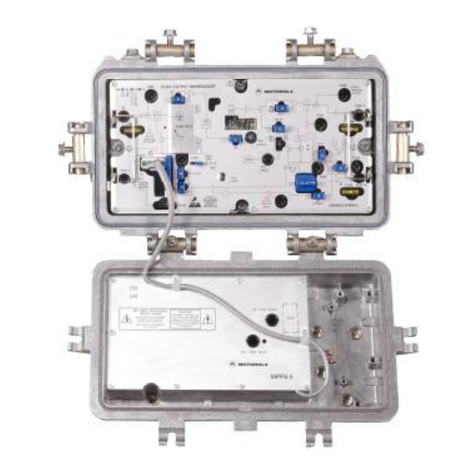
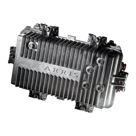
Motorola MINILINE 1000 Series Assembly instructions

MLK Amplifier Installation Sheet
MINILINE 1000
MLK Amplifier
Installation Sheet 494330-001
Motorola’s®MLK high-performance distribution amplifiers are designed for two-way capability
and the sheltered environment of multiple dwelling units. Model MLKL uses coaxial cable
power (line 24 Vac to 65 Vac) while Model MLKM uses utility power (mains 220 Vac to 230 Vac,
50/60 Hz).
This Installation Sheet provides instructions on how to install the MLK amplifier in a CATV
system.
Figure 1 illustrates a closed MLK amplifier:
Figure 1
Closed MLK
Unpacking the MLK
Unpack the MLK amplifier and inspect it for damage. If damage is visible, set it aside in the
original packing material and contact the Motorola Customer Service Department for further
instructions.
Verify that you have received a plastic bag containing: (1) two mounting brackets with two
machine screws and two sheet-metal screws, (2) a ground lug with solderless connector and
machine screw.

2MINILINE 1000
MLK Amplifier Installation Sheet
Configuration
The shipped configuration of the MLK is noted on a label on top of the amplifier. Figure 2
illustrates the configuration notation:
Figure 2
Configuration notation
Key
L
M
Powering
Line powering
Mains powering
Key
0
X
2
4
6
8
10
12
dB Value Output Slope
Jumper
None
2 dB
4 dB
6 dB
8 dB
10 dB
12 dB
Key
8Bandwidth
870 MHz
Key
32
38
Gain
32 dB
38 dB
Key
X
B
Supply Options
None
Battery back-up
Key
XReserved
Reserved
Key
K
F
M
C
I
Input/Output Connectors
KS conn, 5/8-24
F conn
KS input and F output conn
IEC input and F output conn
IEC type
MLK 8 G XXX
Key
GTechnology
Key
A
K
E
S
Frequency Range
5-65 MHz, 85-870 MHz
5-42 MHz, 54-870 MHz
5-30 MHz, 47-870 MHz
5-40 MHz, 52-870 MHz
Key
S
H
Output level
Standard output
High output
Before You Begin
Before you install the MLK, verify that the following conditions are met:
! The MLK operating voltage must conform to the local utility voltage.
! Grounding is according to the national standard
! Protection is class II
! Use only the supplied power cable (mains ac power)
! Use fuses with the rating indicated on the power supply cover
! Use the MLK within its ambient temperature rating (−20°C to +55°C)

MINILINE 1000 3
MLK Amplifier Installation Sheet
DANGER!
When the power supply cover is removed, high-voltage components are exposed.
Installing the MLK
To install the MLK:
1 Use the two machine screws to install the two mounting brackets on the back of the
amplifier. Use the threaded holes that best match the mounting surface.
2 Use the two sheet-metal screws to secure the MLK brackets to the mounting surface.
3 Connect the input coaxial cable to the input connector on the bottom left of the MLK (item
10 in Figure 3). See Table 1, Key 10 for possible types of connectors.
4 If applicable, use a 2 mm Allen wrench to torque the center-conductor seizure screw to 6.5 to
9 in-lbs (0.5 to 0.75 N•m). See Table 1, Key 9 for description.
5 Connect the output coaxial cable to the output connector on the bottom right of the MLK
(item 14 in Figure 3). See Table 1, Key 14, for possible types of connectors.
6 If applicable, use a 2 mm Allen wrench to torque the center-conductor seizure screw to 6.5 to
9 in-lbs (0.5 to 0.75 N•m). See Table 1, Key 15 for description.
7 Applying power:
If using Model MLKL, completion of Steps 3 and 4 provide system cable power (24 Vac
to 65 Vac) to the amplifier.
If using Model MLKM, system cable power is not available and the attached power cord
(item 8 in Figure 3) must be connected to utility power (220 Vac to 230 Vac, 50/60 Hz).
8 Attach the ground lug to any of the threaded holes on the back of the MLK using the
machine screw provided.
9 Crimp the solderless connector to a suitable wire and slip over the flat on the ground lug.
10 Connect the other end of the wire to ground.

4MINILINE 1000
MLK Amplifier Installation Sheet
Figure 3 illustrates an open MLKM and the user related features:
Figure 3
Open MLKM
DISCONNECT FROM REMOTE
SUPPLY BEFORE OPENING.
25 mm
1 : 1
POWER
POWER SUPPLY
V : 24 - 65VAC
V :12 VDC
I : MAX. 1.0 A
FUSE: T2A
REMOVE COVER
TO CHANGE FUSE.
OUT
IN
OUT
8
SEZ
JXP IN
-20 dB
IN
RTN
EQ
FWD
EQ
HJXPOUT
L
-20 dB
JXP IN
H
L
OUT
-20 dB
13 5476
2
910 11 12 151413
Table 1 identifies and describes the user-related features of the MLKM illustrated in Figure 3:
Table 1
MLKM features
Key Description
1 −20 dB forward-path input and return-path output test point
2 Removable diplex filters
3 Forward path equalizer pad (JXP-*B)
4 Forward path attenuator pad (JXP-* B)
5 Forward path interstage module for tilt (SEZ9**)
6 −20 dB return-path input test point
7 −20 dB forward-path output test point
8 Input power connector-Model MLKM only (mains powered 220 Vac to 230 Vac, 50/60 Hz)
9 Input seizure screw
10 RF input connector options: F-type, KS, IEC
11 Return-path output attenuator pad (JXP-* B)
12 Return-path interstage equalizer pad (JXP-* B)
13 Return-path input attenuator pad (JXP-* B)

MINILINE 1000 5
MLK Amplifier Installation Sheet
Key Description
14 RF output connector options: F-type, KS, IEC
15 Output seizure screw
Leveling the MLK
For uninterrupted signal-level adjustment, you can use the test points located inside the
amplifier adjacent to the RF input (item 1) and the RF output (item 7) in Figure 3. These test
points are 20 dB below the signal level.
You can level the signal by installing attenuator pads at the equalizer pad location (item 3). As
slope is a permanent function of the circuit board, compensation for frequency related loss is
made with your choice of attenuator pads (JXP-*B).
To install JXP-*B attenuator pads at any pad location:
1 Separate the upper (handle) portion from the pad as illustrated in Figure 4:
Figure 4
JXP-*B attenuator pad
2 Use needle nose pliers to insert the pad in the proper location.
If you need to provide a sloped output, you must only use interstage modules from the SEZ9**
series. The module you select determines the slope characteristic. Changing the slope does not
change the noise figure of the MLK. Gain is changed by installing an attenuator at the input
(item 4).
Return Path
The return-path amplifier is integrated on the circuit board. You can use the −20 dB
return-path input test point (item 6) for testing both return-path input and lead-in signals. The
−20 dB test point (item 1) can also be used to test the return-path output. Regulation of gain
and slope is performed with attenuators of appropriate value placed in pad locations 11, 12, and
13. Table 1 describes the functions of these pad locations.

6MINILINE 1000
MLK Amplifier Installation Sheet
Closing the Housing
Before you close the housing:
1 Inspect the RF and weather gaskets for damage and replace if necessary.
2 Confirm that the center-conductor seizure screws are torqued to 6.5 to 9 in-lbs
(0.5 to 0.75 N•m) (applicable only to KS or IEC connectors).
3 Close the housing and use a 4 mm Allen wrench to torque the bolts to 3 ft-lbs (4.1 N•m).
If You Need Help
If you need assistance while working with the MLK, contact the Motorola Technical Response
Center (TRC):
! Inside the U.S.A.: 1-888-944-HELP (1-888-944-4357)
! Outside the U.S.A.: 1-215-323-0044
! Online: http://www.motorola.com/broadband, click HTML/Modem
Version, click Customer Support, then click Web Support.
The TRC is open from 8:00 AM to 7:00 PM Eastern Time, Monday through Friday and 10:00 AM
to 6:00 PM Eastern Time, Saturday. When the TRC is closed, emergency service only is
available on a call-back basis. Web Support offers a searchable solutions database, technical
documentation, and low priority issue creation/tracking 24 hours per day, 7 days per week.
Motorola BCS UK Motorola BCS Germany
Imperium, Imperium Way (Fuba Communications Systems GmbH)
Reading, Berkshire TecCenter
RG2 OTD D-31162 Bad Salzdetfurth
United Kingdom Germany
Tel: +
++
+44 118 975 5555 Tel: +
++
+49 (0) 50 63 89 0
Fax: +
++
+44 118 975 3933 Fax: +
++
+49 (0) 50 63 89 566

CAUTION
RISK OF ELECTRIC SHOCK
REFER SERVICING TO QUALIFIED SERVICE PERSONNEL.
TO REDUCE THE RISK OF ELECTRIC SHOCK,
DO NOT REMOVE COVER (OR BACK).
NO USER-SERVICEABLE PARTS INSIDE.
CAUTION:
Caution
These servicing instructions are for use by qualified personnel only. To reduce the risk of electrical shock, do not perform any servicing other
than that contained in the Installation and Troubleshooting Instructions unless you are qualified to do so. Refer all servicing to qualified service
personnel.
Special Symbols That Might Appear on the Equipment
This symbol indicates that dangerous voltage levels are present within the equipment. These voltages are not
insulated and may be of sufficient strength to cause serious bodily injury when touched. The symbol may also
appear on schematics.
The exclamation point, within an equilateral triangle, is intended to alert the user to the presence of important
installation, servicing, and operating instructions in the documents accompanying the equipment.
For continued protection against fire, replace all fuses only with fuses having the same electrical ratings marked
at the location of the fuse.
Electrostatic discharge (ESD) can damage the MLK. Wear an antistatic wrist strap attached to a chassis ground
to prevent ESD damage.
This equipment operates over the marked Voltage and Frequency range without requiring manual setting of any
selector switches. Different types of line cord sets may be used for connections to the mains supply circuit and
should comply with the electrical code requirements of the country of use.
CAUTION: TO PREVENT ELECTRICAL SHOCK, DO NOT USE THIS PLUG WITH AN EXTENSION CORD, RECEPTACLE, OR OTHER
OUTLET UNLESS THE BLADES CAN BE FULLY INSERTED TO PREVENT BLADE EXPOSURE.
CAUTION: TO ENSURE REGULATORY AND SAFETY COMPLIANCE, USE ONLY THE PROVIDED POWER CABLES.
It is recommended that the customer install an AC surge arrestor in the AC outlet to which this device is connected. This is to avoid damaging the
equipment by local lightning strikes and other electrical surges.
Changes or modification not expressly approved by the party responsible for compliance could void the user’s authority to operate the equipment.
8MINILINE 1000
Declaration of Conformity
We Motorola, Inc.
101 Tournament Drive
Horsham, PA 19044, U.S.A.
declare under our sole responsibility that the
MINILINE 1000 Model MLK Series Amplifiers
to which this declaration relates is in conformity with one or more of the following standards:
EMC Standards
EN50083-2
Safety Standards
EN50083-1
following the provisions of the Directive(s) of the Council of the European Union:
EMC Directive 89/336/EEC Low Voltage Directive 73/23/EEC
MOTOROLA and the Stylized M Logo are registered in the US Patent & Trademark Office. All other product or service names are the
property of their respective owners. Motorola, Inc. 2002.
494330-001
8/02
All rights reserved.
No part of the contents of this manual may be reproduced or transmitted in any form or by any means without the
written permission of the publisher.
MGBI
This manual suits for next models
3
Table of contents
Other Motorola Amplifier manuals

Motorola
Motorola SG4-OA User manual

Motorola
Motorola Micom 1000 User manual

Motorola
Motorola MB87 User manual

Motorola
Motorola Mostar HSN1000A User manual

Motorola
Motorola MSR 2000 User manual

Motorola
Motorola Signal Booster User manual

Motorola
Motorola NSN6027A User manual

Motorola
Motorola HSN4035 Operating instructions

Motorola
Motorola STARLINE SERIES User manual

Motorola
Motorola Signal Booster Manual