Precautions
and
table
of
contents
Thank
you
for
purchasing
this
AKAI
amplifier.
To
ensure
opti-
mum
performance
of
the
unit,
please
read
this
operator’s
ma-
nual
thoroughly.
This
operator's
manual
applies equally
to
models
AM-59
and
AM-69
except
where
otherwise
noted.
WARNING
To
prevent
fire
or
shock
hazard,
do
not
expose
this
ap-
pliance
to
rain
or
moisture.
1-En
Power
requirements
Power
requirements
for
electrical
appliances
differ
from
area
to
area.
Please
ensure
that
your
appliance
meets
the
power
requirements
in
your
area.
If
in
doubt
consult
a
qualified
electrician.
220-230V,
50Hz
for
Europe
except
U.K.
This
equipment
conforms
to
NO.82/499/EEC,
87/308/
EEC
standard.
3A-En
CONFORME
AL
D.M.
13
APRILE
1989
DIRETTIVA
CEE/
87/308.
3B-It
About
the
POWER
switch
This
amplifier
is
not
equipped
with
a
primary
power
switch.
Even
when
the
amplifiers
POWER
button
is
set
to
STANDBY
(off),
the
power
supply
to
this
amplifier
is
not
completely
turned
off.
If
you
wish
to
completely
turn
the
power
off,
disconnect
the
power
cord
from
the
househoid
AC
outlet.
4-En
Table
of
contents
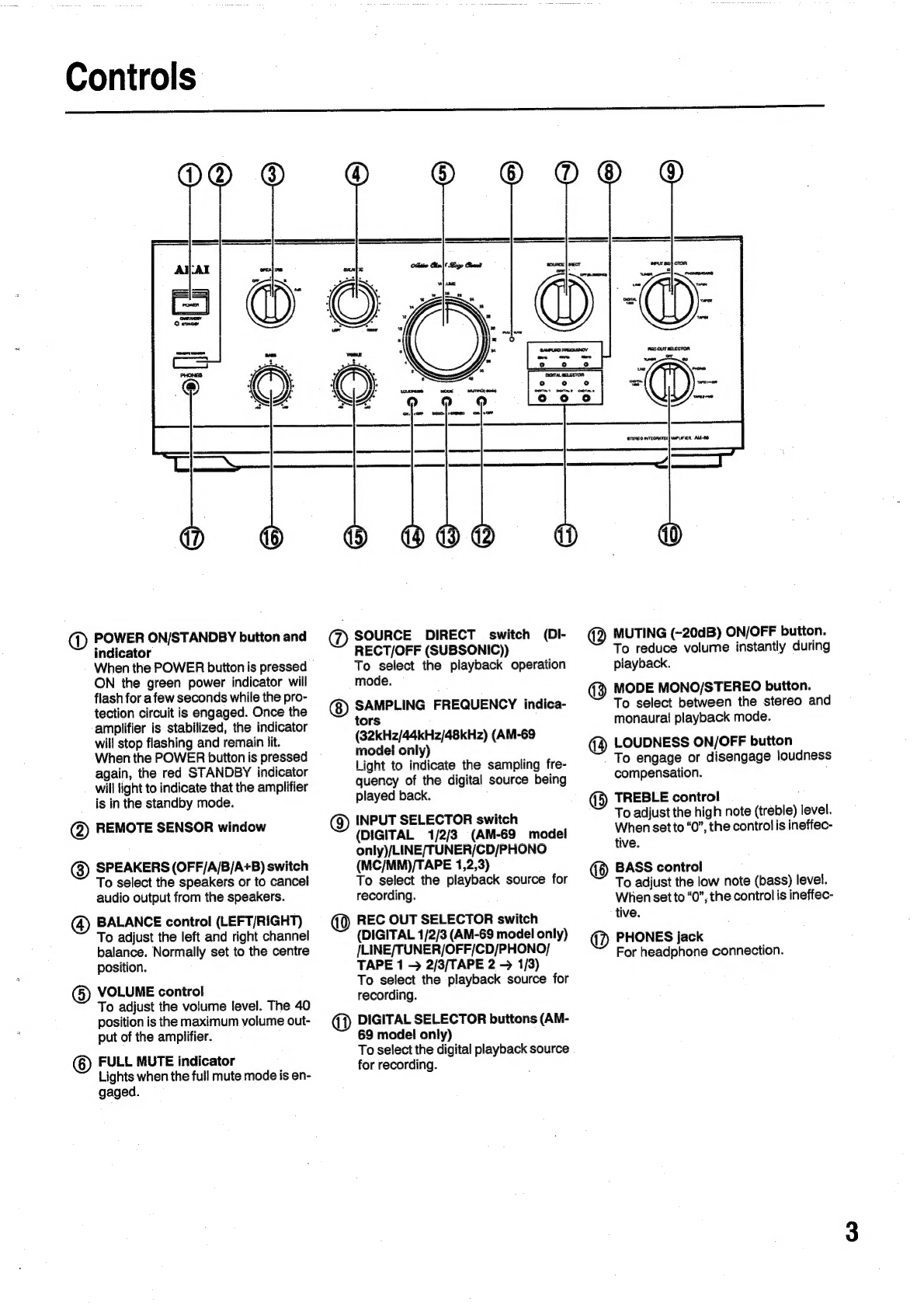
COMtrOlS
......ccccsccscsececsecsecencaseaseosscessuscenecesseesecepeuennonss
3
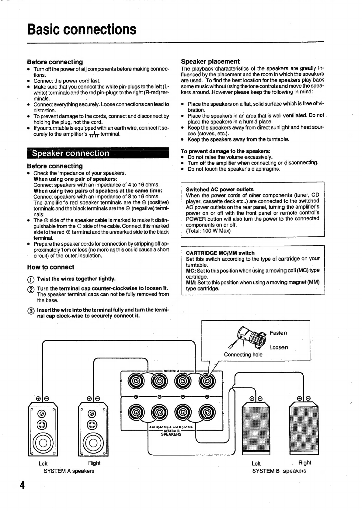
BASIC
CONNECTIONS
..........cceeceeeeceeseseeceeeesaneeeenerenoneeenes
4-5
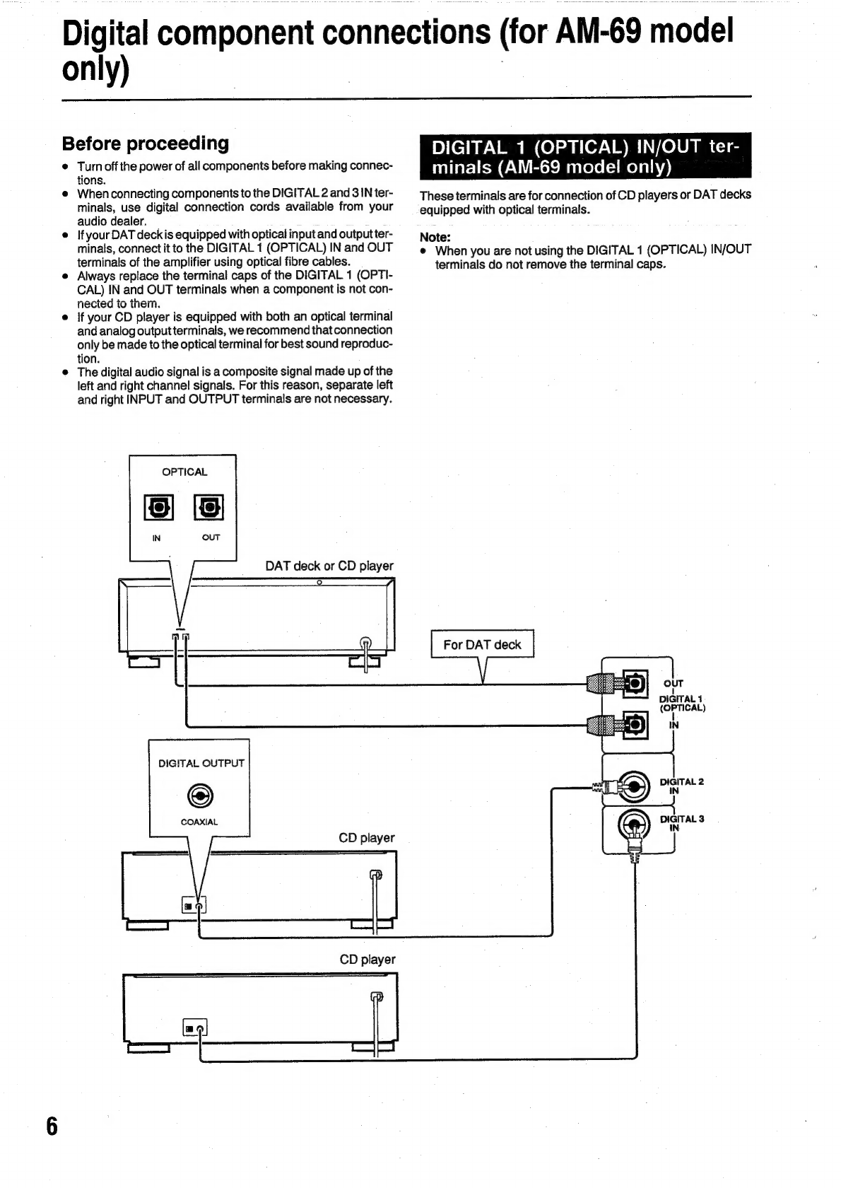
Digital
component
COMNECtiONS
........ccccccceceseeeeeterententteees
§
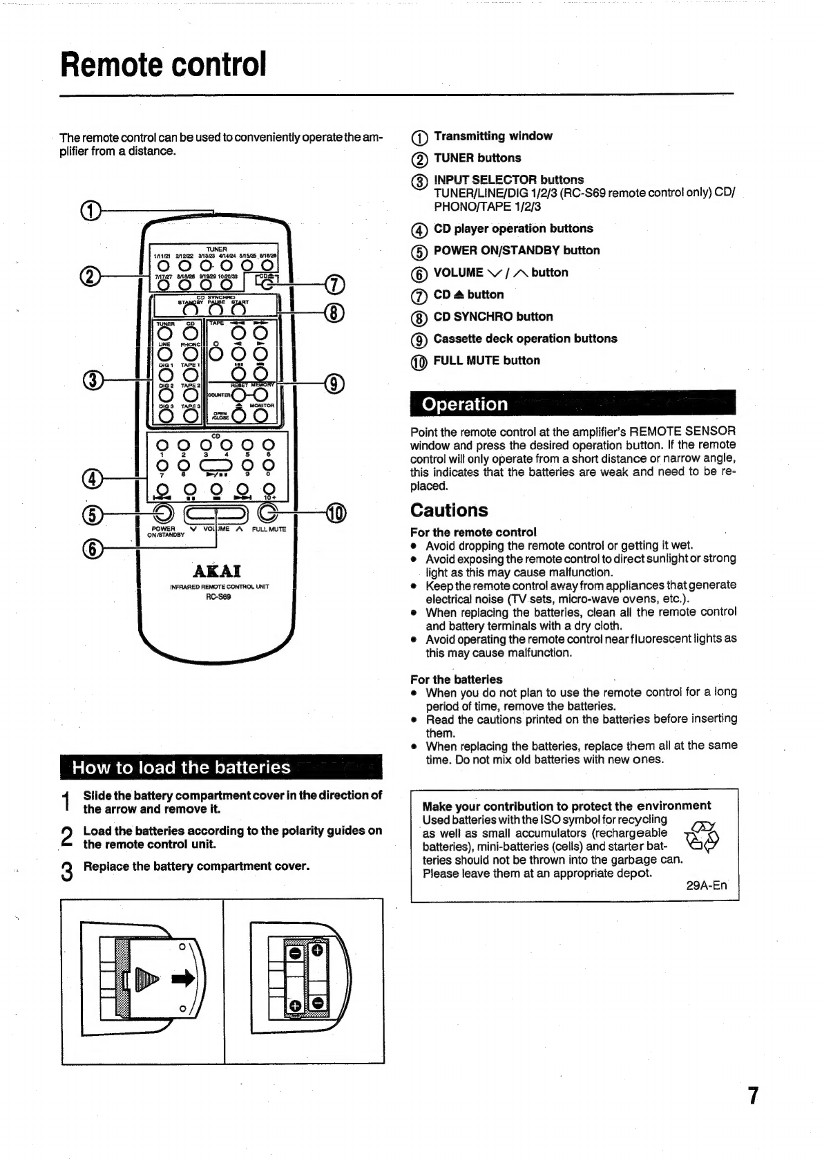
REMOtE
CONTIO!
......c.:cecceeseeceesaeeescneeecsseeeneseneeeseneoes
ones
7
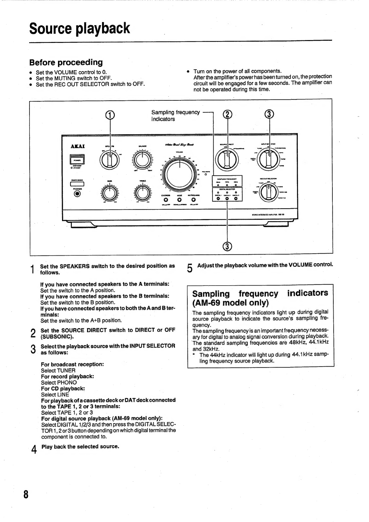
Source
playback
..........ccccseeceecssssseenseenseaessntaeenseessaaanes
8
Operation
details
.........cccccecssssereeesensennercseeneeneenenes
9-10
RECOIING
.........eeeceeeceeeeceeessensesereuavenseecneeseuanoureneesegs
11
TrOUDICSHOOTING
........c.eceeeseeeeesescnsnnsenensecnesaeeesenseeesens
12
Specifications
.........cccceessseessseeuesseveceacseensnsesnenseeeanenes
13
What
you
should
know
to
protect
yourself
Never
touch
the
power
cord’s
plug
with
wet
hands.
Always
pull
the
power
cord
out
by
its
plug,
never
by
its
cord.
Only
let
a
qualified
professional
repair
or
reassemble
the
am-
plifier.
An
inexperienced
person
might
touch
the
internal
parts
and
receive
a
serious
shock.
Never
put
anything,
especially
metal
into
the
amplifier.
_Protect
the
amplifier
too...
Use
a
household
AC
power
source
only.
Never
use
a
DC
power
source.
If
water
is
spilled
on
the
amplifier,
disconnect
it
and
call
your
dealer.
Make
sure
that
the
amplifier
is
well
ventilated
and
away
from
direct
sunlight.
To
avoid
damage
to
the
internal
circuits
and
the
external
sur-
face,
keep
the
amplifier
away
from
heat
(stoves,
etc.).
Avoid
using
aerosol
sprays
near
the
amplifier
as
this
could
damage
the
finish
or
cause
sudden
ignition
of
the
spray.
To
avoid
damaging
the
finish,
never
use
paintthinner
or
other
similar
chemicals
to
clean
the
amplifier.
Place
the
amplifier
on
a
flat
and
solid
surface.
if
you
do
not
pian
to
use
the
amplifier
for
along
period
of
time,
disconnect
the
power
cord.
Keep
the
cabinet
clean
Clean
the
cabinet
with
a
soft,
dry
cioth.
e
Ifthe
cabinet
is
very
dirty,
clean
it
with
a
mild
detergent.
©
Never
use
paint
thinner,
etc.
to
clean
the
cabinet
as
this
may
damage
the
finish.