Motorola VWAT User manual

GENERAL I NFORMAT ION
TYPE - Automotive type superheterodyne receiver designed
for custom installation in the 195?, L956, 1955,
1954 & 1953 Volkswagen cars"
TUNING RANGE - 535 to 1605 Kc IF - 262.5 Kc
OPERATES FROM - 6 volt storage battery
TUBE COMPLEMENT - 6BE6 Converter
68A'6 tF amp
6cR6 DeI-AVC-AF amp
5AO5 Pwr amp
6X4 Rectif ier
Thisreceiverhas anautomatlc tuner, with 5 pushbuttons
for automatic station selection.
To set the pushbuttons for automatic tuning, proceed as
f o11ows:
1. Tue in the desired siation with the maaual tuning knob.
Tune carefully until you are exactly on the station.
MOTOROLA AUTO RAD IO WARRANTY SERVICE
l, The definition of a Motorola Branded Model is one that
is branded with the Motorola name, and distributed to
dealer s thr ough authorized Moto rol.a Dis tributor s .
Z. Before performiag a warranty repair on a Motorola
Branded Auto Radio, you must first receive from the cus-
tomer the Customerts Warrmty Policy. This policy must
be ftlled out by the selling dealer at the time of retail pur-
chase. The Customerrs Warranty Policy must show tbe
radio to be within the ninetv 4av yra.ranty.period if the re-
pair is to be handledffidio l,Van-
ranty Plan.
3, The removal or reinstallation of the radio, the elimina-
tion of moior noise" tire static, electrical interference, or
faulty installation and aerial repairs are not considered as
warranty repairs. Consequently, charges for these serv-
ices are to be borne by the customer"
TO SET PUSHBUTTONS
Price LO Cents
2. Pull out the first pushbuttons to be set, to unlock the
button for station set-rp, and then push button in firmly to
set and lock the button.
3" Follow the above procedure for the remaining four but-
tons,
STATION PROCEDURE FOR BRANDED MODELS
4. Fill in the Motorola Auto Radio Warranf,y Labor Claim,
Part No, 54P480884, and mail Whlte and Green copies to
the Motorola Distributor serving your area. The Yellow
copy is to be retained by the Warraaf,y Service Station for
his files"
5. Defective parts for warranty repairs made on Motorola
Branded Auto Radios are to be sent to your MotorolaDis-
tributor for free replacement, supported with the defective
parts return form which you are now using.
6" Only those service shops authorized by their Motorola
Distributor can per{orm repairs *'ithin the warranty period
on a no-charge basis to the customer. If you are not al-
ready authorized as a Motorola Auto Radio Warranty Serv-
ice Station, and you are interested in handling this service,
please contact your Motorola Distributor for complete de-
tails"
AUTO RAD I O
MODEL
VWAT
. cHtcAGo 51, tLLtNOtS
IUOTC'ROLA
Part No. 68P541456 Printed in U.5;A.

STEP GENERATOR
CONNECTION
GENERATOR
FREOUENCY
(400 cycle mod) TUNER SET TO ADJUST REMARI(S
iF AL
t.
RF AL
z.
iNMENT
Ant recept through
.lmf&chassis
GNMENT
Ant recept through
dummy ( eee Fig. )
262"5 Kc
1610 Kc
Hi end stop
Hi end stop
I,2,3&4
5,6&7
Adjust for maximum.
Adjust for muimum.
AL IGNMENT
Connect an output meter across tbe speaker voice coil. Set volume to ma:<imum and tone to treble. Atteauate the eignal gen-
erator outp'ut to malntain 1.79 volts on output meter at all times to prevent overloadiag the receiver.
NOTE: Do not perform step6 3, 4, 5 & 6 unless the tuner has been tampered with or corirponents ba,ve been replaced. Re-
movetheescutcheon,dialscileassemblyanddialbackgloundplatetoexposethecorescreq/st. BefoteproceediogwitJrstep3,
b4ckt}le tuning cores as far as posslble out of the colls to eliminate their effect ontrimmer adjustmente"
3.
+,
5.
6. Repeat steps 4 and
I
ANTENNA TRIMMER
7" I -
I
I
GENERATOR
weak gtation I
around 1400 Kc I
Adjust for maximum.
Adjust for maximum.
Adjust for maximum.
Step 5 should be the last adjustment.
'Wlth radio lnstalled in car and an-
tenna fully extended, adjust anten-
na trimmer for muimum.
DIITTT AXTEtrXA
DETAIL
Ant recept through
dumrny (see Fig" )1610 Kc
1200 Kc
l6l0 Kc
no further
Hi end stop
Tuner carrlage
9 /3zt' tuorn bl
end stop
Hi end stop
increase, then cement tuing
5,6&?
8,9&lo
s,6&7
6CR6
DtT"AVC.AF
5 until corea in place.
'l
PLUG TO FIT RECEIVER
ANTENNA RECEPTACLE
D0tfi--14
;[__ili
T2 CONN
-'*fi-ilz
,1, ,1,
TI CONN
TO RECEIVER
+ANTENNA
RECEPTACLE
TO PLUG
6BA6
NOTES:
CAPACIToRS' Decimal values in MF, all others
in MMF unless otherwise 5p&lfled.
VoLTAGES: Measured fron point indicaled to
chassis with a WVI/L No siqnal input.
Tolerance+ l0*.
INPUI VOTi-A6E, 7V
TUNING RANGI, 535 KC to 1605 KC.
ti 262,5KC,
"l ts
-*i I
e+,si
]50 NoM i
SCEEIATIC DIAGBAI

AI,ICrISXT .IDJIFTISXTS At[D PARTS I,OCATIOIS
68A6
IF A'IIP
6CR6
DET-AVC-AF
ctz
cll
R6
cl0
R5
R8
R9
Rl2
-t5
R16
Rl7
RU
@c5
13
R4 rilt
CI
c6 (-
6X4
RECT PWR AMP
c19
-14
Ru

REPLACEMENT PARTS LIST
NOTE3 When ordering parts, specify model uunber of set in addj.tion to part nwber and description of part, Llst
Price
Ref. Part
No, Nunber
ELECTRICAL PASTS
c-1 20K541699
c-2 8R121568
c-3 +20K542018
c-4 21R410089
c-5 8R121005
c-6 21R410036
c-7 *20K542092
c-8 21R115593
c-9 8R12L567
c-r.0 88121868
c-tr 8R121567
c-I2 2tRt2t946
c-13 8R121568
c-14 8R121868
c-15 2IR114554
c-16 23A485677
c-I7 8R121000
c-18 64K530t77
c-19 4KL22076
c-20 8K122076
c-2t 8Rt2ro04
E-l 50C54110r
E-2 65R16248
E-3 65R10867
E-4 4883333
L-r, 2 &,3
L-4 +24K5420t9
L-5 24A538914
Resistors - Note:
R-l 6R6004
R-2 6R6028
R-3 6R2036
E-4 6R5690
R-5 6R2lt8
R-6 6R6028
R-? +188542013
R-8 6R21r8
R-9 6R6004
R-10 6R6015
B-11 6R6014
R-12 6R6270
B-13 6R6032
B-14 6R476130
B-15 6R6330
R-L6 6R2037
R-17 6R2037
T-1 2i1B580193
T-2 24X591267
T-3 25870777
T-4 25C537r64
IIEC]IANICAL PARTS
*78541865
+7C54L894
*43K541923
42A500196
Descript ion List Ref.
Price No-
Capacltor, nica trin: 35 mf to 2O0 mf -50
Capacitor, paper tub: .OO2 mf 60Ov,. - .30
Gepacitor, nica trim: 20 mf to 120 mf ,45
Capacitor, cer disc: 27 Mf sOOV".., " "25
capacitor, paper tub3 "05 nf 2oov.... "25
Capacitor, cer discr 1O0 mf sOOV
NTC7soPpil. .25
qapacitor, mica trimr 3I0 mf to 390 mf .75
Capacitor, cer disc; 47 mf 5OOV
NTC75oPpM, .25
Capacitor, paper tubg . 05 nf 4OOV, . . , .25
Capacitor, paper tubs ,01 nf 2OO!.,-. -25
Capacitor, paper tub: .05 nf 4OOV.. ". .25
Capacitor, cer disc; . 0l nf sOOV. . , . . "25
Capacitor, paper tub: .OO2 nf 6OOV, " " .30
Capacitor, paper tub: . 01 nf zOOv. " . " ,25
Capacitor, cer disci 470 mf sOOV-,,. .25
Capacltor, electrolytic: IO-15nf,/350v;
2oaf/25!. 3. 05
Capacitor, paper tub: ,004 nf 60OV.,, "35
Spark Plate. .05
Capacitor, paper tubS ,5 mf 100V",... "50
Capacitor, paper tub: ,5 nf loov,. ^,^ ,50
Capacitor, paper tub: . 02 nf IOOOV, , ^ ,35
Speaker, Plr: 6 x 9i; 3.2 ohn VC"... ". . '7.75+*
Fuse, 9 anp"..,. ,05
Bulb, pilot llght: 6\t #44. .2O
Vlbrator, 6V, ..,. "
See Tuner Replacenent Parts List
Choke, RF. .05
Choke, hash, .35
AII resj.stors are insulated carbon type
unless otherwise specif ied
I neg, 2q L/2v.... ,1o
22,OOO 2@o r/2V.... .. .10
33 L& r/211.... . ro
6800 L@, N, ,25
3,3 neg 2@ L/zu."." ." ,10
22,OOO zrk r/m.... .. ,1o
Dual Control & Swltch: voL 2 neg, tap
at 1 neg; toDe 500K, .. 2.25
3.3meg 20% I/2f,... .10
Lneg.zCX" I/zv"... .10
22O,OOO 2qa L/N,... ,10
330,OO0 20% r/21t... . .10
220 rw" r/zv.... .10
47O,OOO 2& L/zV.... .rO
22OO 2& 2\1..,... .25
150 tq. 1fi...,., .2o
56 LW 1{,,..,. .2O
56 LU$ 1l{.,..,. .2O
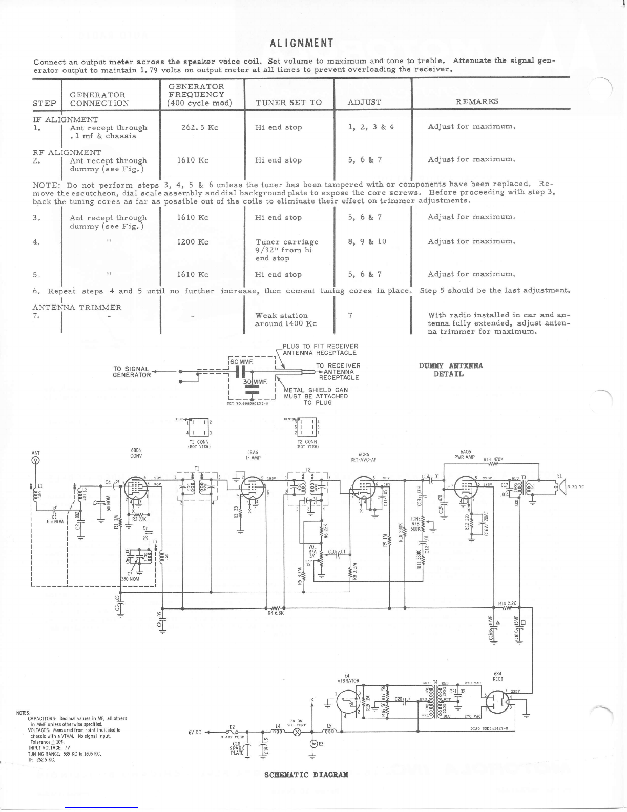
Transformer, 1st IF: 262.5 Kc. L.45
Transforner, 2nd IF: 262,5 Ke. 1"70
TraDsformer, output,, .. 1.90
TraDsforner-, pover,.. .. 4.30
Bracket, dial background,...... ,4O
Bracket, dial scale ret,..., .15
BuEhlng, ntg.... .4O
Clip, dial icale ret. .. .O2
428733793 CIip, IF ntg...,. ,O2
42A42L5 Clip, vibrator grounding. .I0
*15K541823 Cover, bot" .45
15C541670 Cove", top. .45
*138541930 Escutcheon. 1,50
+36K542005 Knob, dumy. "4O
368522020 Knob, toDe. .4O
+36K542194 Knob, vol & tuning. .3O
2852L332 Nut, clinch (staked to housing) .O2
*LY5422L4 Pointer.
38C541147 Pushbutton" . ".;, .. . ,10
*9K541991 Receptacle, fuse,... "7O
*348542050 Scale, dial. .2O
:18541917 Shaft, nanual tuning: incl bushiDg.,.. t. t5
9A530168 Socket, ant. "2O
9A7O2O8 Socket, 4 pin (vibrator).".".. .2O
9K541697 Socket, pilot l-ight. .2O
9K539I32 Socket, tube: 7 pin min" ,15
29A762A0 Terninal, pin: black (6pkr leads). ... , .05
29K76282 Termlnal, pl.n: white (spkr leads),..,. .03
4K481689 Washer, lelt (cont knobs) . . . 01
ITOUNTING PARTS & ACCESSOAIES
*78542000 Bracket, rcvr ntg" .10
64C52O2O2 Plate, spkr ntg. " ",, I.65
*1Y542033 Kit, ntg parts: incl ltens listed below 1.10
AA449l Condenser, Dolse suppressj.on.. "..... ", " .85
457657 Lockwasher, ext: #4...... .01
457688 Lockwasher, int-ext3 5/8 x l/4 (tavt
ntg)... .01
257003 Nut, hex: a-32 x 5/16 (spkr ntg).,,,.. .01
252A79 Nut, hex: 7/16-2A (rcvr ntg) ,. .05
358039 Screw, cap: l/4-2O x 3/8 (tcvr ntC)"., .05
+35122799 Screw, tappingz #6 x 3/8. .01
457550 Ifasher, flat: 7/16-.156-.O48 ,, .01
2A9L2IL9 llingnut: 8-32 (spkr ntC),.., ,. ,Ol
TI'NER 77K542165 (AT-233) PARTS
L-l
L-2
L-3
Part
Number
24C535458
24C535454
24C535456
+77K542L65
1.B534778
45C534697
1A540830
+45853457 4
43A4326
1V535114
1\542258
76K534642
76K534644
5K5369 r8
5K534727
5K534508
454534509
rK'42255
42K534660
?68534589
41A501096
41A535493
41A534566
4A501039
4A535325
Des cr ipt lon
Coil, ant. .25
Coi1, RF, .25
Coit, osc. .3O
Tuner, AT-233: conplete. ...... I1.95
Ad.justing Screw & Nut Assen. .tO
Arn, Clutch release. .f0
Arn, poiDter" .. .tO
Arn, pushbutton extelsion, .03
Bearlng, ba11,",. "Ol
Clutch Assen: lncl frictlon washers,
crovn gear & pinion gear,... ,, 2.2O
Cotls & l[tg Plate Assen: iqcl^ Ll, L2,
L3 & mtg plate.,. 2.55
Core, iron (ant & RF coil)... .. .55
Core, iron (osc coil) .. .55
cromet, coil ntg (ant & RF coll)...... .03
Gromet, coil mtg (osc coit) ,O2
Gromet, core Btg, .O2
Link, connectitg...... .01
Plate, coil ntg,,.., ,2O
Retainer, c1utch,. "2O
sleeve, iron. ,, ,o5
Sprlng, pointer. ,10
Spring, lension (clutch bar return) . . , . .03
Spring, tensLon (conn link).........,.. .05
lfasher, ric" (pointer arn).... .. ,01
ffasher, rubber (sleeve ret). . . . .O2
PRICES SI'BJECT TO CNAIGE WITEOIJ'T NOITICE
*New Item, Appears in any List for Flrst Tlne
**P1us Federal Exci6e Tax at Current Rate

AUTO RADIO
SUPPLEMENT NO.
MODEL
VWAT
SUPPLEMENT TO VWAT SERVICE MANUAL PART NO. 68P541456
GENERAL INFORMATION
This supplement coversparts used on Model VWAT auto all other i.nformation, refet to the V'[{IA7 Service Manul
radio when it is installed in a 1958 Volkswagen car. For (Part No. 68P54I456).
SUPPLEMENTARY REPLACEMENT PARTS LI ST
NOTE: l{hen orderlng parts, specify nodet nunilcer of set ln addition to part nunber aBd descriptLon of part.
Electronic parts of equivalent rathg are not necessarlly of equivalent standards, The components
listed j.n this Service ltaDual have been chosen for reliabllity and appllcablllty to the specific
clrcuits involved. For mxlnm customer satlsfactlou and ml.ni.mlzed call-backs, use the ex&ct
!'lotorola parts replacenent.
Descr ipt ion Ref. Part
No. Nunber Description
A8538244 Condenser, voltage regulator
13B542?80 Escutcheon
252a79 Nut, hex3 7/L6-2a (rcvr ntg)
348542775 Sca1e, dial
35128062 Screw, tapping: #lO x 3,/8 (spkr ntg)
6A4L4I Suppressor, distributor
ts are used when
tNes lten, Appears in any Llst for Flrst Tine
Ref.
No. Part
Number
78542795
7K542794
7s542?67
+43K3427?6
Bracket, rcvr ntg: LH (dash)
Bracket, rcvr ntg: RU (dash)
Bracket, rcvr mtg (rear)
Bushing, ntg: l-5116 long overall
,woroFtolA ,N(c.
Part No. 68P542591
WEST AUGUSTA BLVD.
Price 5 CeDts
51, ILLINOIS
Printed in U.S,A
4545 cHr.cAGo
This manual suits for next models
1
Table of contents
Other Motorola Car Receiver manuals