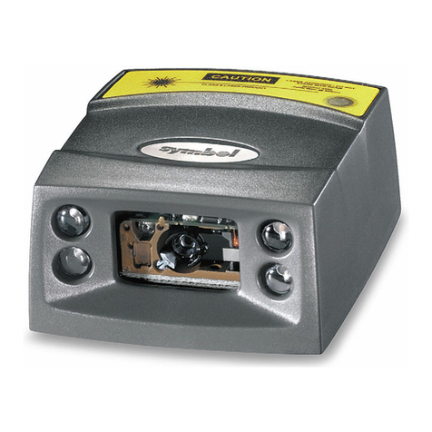
Motorola SE4750 Quick setup guide

SE4750
INTEGRATION GUIDE


SE4750
INTEGRATION GUIDE
72E-171726-01
Revision A
November 2013

ii SE4750 Integration Guide
© 2013 Motorola Solutions, Inc. All rights reserved.
No part of this publication may be reproduced or used in any form, or by any electrical or mechanical means,
without permission in writing from Motorola. This includes electronic or mechanical means, such as
photocopying, recording, or information storage and retrieval systems. The material in this manual is subject to
change without notice.
The software is provided strictly on an “as is” basis. All software, including firmware, furnished to the user is on
a licensed basis. Motorola grants to the user a non-transferable and non-exclusive license to use each
software or firmware program delivered hereunder (licensed program). Except as noted below, such license
may not be assigned, sublicensed, or otherwise transferred by the user without prior written consent of
Motorola. No right to copy a licensed program in whole or in part is granted, except as permitted under
copyright law. The user shall not modify, merge, or incorporate any form or portion of a licensed program with
other program material, create a derivative work from a licensed program, or use a licensed program in a
network without written permission from Motorola. The user agrees to maintain Motorola’s copyright notice on
the licensed programs delivered hereunder, and to include the same on any authorized copies it makes, in
whole or in part. The user agrees not to decompile, disassemble, decode, or reverse engineer any licensed
program delivered to the user or any portion thereof.
Motorola reserves the right to make changes to any software or product to improve reliability, function, or
design.
Motorola does not assume any product liability arising out of, or in connection with, the application or use of
any product, circuit, or application described herein.
No license is granted, either expressly or by implication, estoppel, or otherwise under any Motorola, Inc.,
intellectual property rights. An implied license only exists for equipment, circuits, and subsystems contained in
Motorola products.
MOTOROLA, MOTO, MOTOROLA SOLUTIONS and the Stylized M Logo are trademarks or registered
trademarks of Motorola Trademark Holding, LLC and are used under license. All other trademarks are the
property of their respective owners.
Motorola Solutions, Inc.
One Motorola Plaza
Holtsville, New York 11742-1300
http://www.motorolasolutions.com
Warranty
For the complete Motorola hardware product warranty statement, go to:
http://www.motorolasolutions.com/warranty

iii
Revision History
Changes to the original manual are listed below:
Change Date Description
-01 Rev A 11/2013 Initial release

iv SE4750 Integration Guide

TABLE OF CONTENTS
About This Guide
Introduction ................................................................................................................... ix
Chapter Descriptions..................................................................................................... ix
Notational Conventions................................................................................................. x
Related Documents....................................................................................................... x
Service Information....................................................................................................... xi
Chapter 1: Getting Started
Introduction .................................................................................................................. 1-1
SE4750 ........................................................................................................................ 1-2
Aiming System ....................................................................................................... 1-3
Aiming Error ........................................................................................................... 1-3
Aiming Control ........................................................................................................ 1-3
Illumination System ................................................................................................ 1-3
Illumination Control ................................................................................................ 1-3
Frame Rate Control ................................................................................................ 1-3
Chapter 2: Installation
Introduction .................................................................................................................. 2-1
General Information ..................................................................................................... 2-1
Default Power Mode ............................................................................................... 2-1
Grounding .............................................................................................................. 2-1
Electrostatic Discharge (ESD) ................................................................................ 2-2
Environment ........................................................................................................... 2-2
Power Supply Noise ............................................................................................... 2-2
Thermal Considerations ......................................................................................... 2-2
External Optics (Imaging Lens, Illumination LEDs, and Aiming Element) .............. 2-5
Image and Document Capture ............................................................................... 2-5
Regulatory Information ........................................................................................... 2-5
Mounting ...................................................................................................................... 2-6
Housing Design ............................................................................................................ 2-7
Optical .......................................................................................................................... 2-7

vi SE4750 Integration Guide
Positioning the Exit Window .................................................................................... 2-7
Avoiding Scratched Windows .................................................................................. 2-7
Window Material ...................................................................................................... 2-8
Commercially Available Coatings ............................................................................ 2-9
A Word About Coatings ........................................................................................... 2-9
Optical Path .................................................................................................................. 2-10
Imaging Field of View .............................................................................................. 2-10
Aiming Pattern ......................................................................................................... 2-11
Imaging and Aiming Parallax .................................................................................. 2-12
Engine Clear Aperture ............................................................................................. 2-13
Recommended Exit Window Information ...................................................................... 2-14
Exit Window Notes .................................................................................................. 2-14
Engine Stray Light Zone .......................................................................................... 2-15
Parallel Window Integration Examples .................................................................... 2-16
Tilted Window Integration Examples ....................................................................... 2-17
Chapter 3: Specifications
Introduction ................................................................................................................... 3-1
Electrical Characteristics ............................................................................................... 3-1
Power, MIPI and Parallel Host Interface ................................................................. 3-1
I2C, MIPI, and Parallel Host Interface ..................................................................... 3-2
MIPI and Parallel Host Interface ............................................................................. 3-2
Parallel Host Interface for HSYNC, VSYNC, PIXCLK, and PIX_DATA_x Signals .. 3-3
MIPI Host Interface ................................................................................................. 3-4
Technical Specifications ............................................................................................... 3-6
Supply Currents VCC = VCC_ILLUM = VDD_IO_HOST = 3.3V @ 23C ...................... 3-8
Parallel and MIPI Host Interface with Laser Aim
(Engine Only without PL3307 Decoder) .................................................................. 3-8
Sample Current Scope Plots ................................................................................... 3-9
Skew, Pitch, and Roll .................................................................................................... 3-11
Decode Ranges ............................................................................................................ 3-12
Chapter 4: Electrical Interface
Introduction ................................................................................................................... 4-1
Connector Drawings ..................................................................................................... 4-3
Power Supply Sequencing ............................................................................................ 4-6
Power-up ................................................................................................................. 4-6
Power-down ............................................................................................................ 4-6
Chapter 5: Control Interface
Introduction ................................................................................................................... 5-1
Command List ............................................................................................................... 5-1
Transactions ................................................................................................................. 5-3
I2C Command Format ............................................................................................. 5-3
I2C Response Format ............................................................................................. 5-3
Command Checksum ................................................................................................... 5-4
Response Status Code ................................................................................................. 5-4
Command Descriptions ................................................................................................. 5-5
Table of Contents vii
ACQUISITION 0x58 ............................................................................................... 5-5

ACQUISITION_MODE 0x5B .................................................................................. 5-5
AIM 0x55 ................................................................................................................ 5-5
AIM_DURING_EXPOSURE 0x56 .......................................................................... 5-5
AUTO_POWER_REDUCTION 0x74 ..................................................................... 5-5

EXECUTE_SCRIPT 0x77 ...................................................................................... 5-5
EXTERNAL_ILLUMINATION 0x5A ........................................................................ 5-5
GET_EXTENDED_STATUS 0x79 ......................................................................... 5-6
GET_PARAM 0x70 ................................................................................................ 5-6
ILLUMINATION_DURING_EXPOSURE 0x59 ....................................................... 5-6
ILLUMINATION_POWER_LEVEL 0xF0 ................................................................ 5-6
IMAGE_CAPTURE_MODE 0x73 ........................................................................... 5-7
PICKLIST_MODE 0x7B ......................................................................................... 5-7
PING 0x7A ............................................................................................................. 5-7
POWER_MODE 0x5F ............................................................................................ 5-7
RD_SENSOR 0x51 ................................................................................................ 5-8
RESET 0x57 .......................................................................................................... 5-8
TIME_TO_LOW_POWER 0x75 ............................................................................. 5-8
WR_SCRIPT 0x76 ................................................................................................. 5-8
WR_SENSOR 0x50 ............................................................................................... 5-8
Command / Response Formats ................................................................................... 5-9
Chapter 6: Application Notes
Introduction .................................................................................................................. 6-1
Image Acquisition ......................................................................................................... 6-1
Output Data Format ............................................................................................... 6-2
Output Data Timing ................................................................................................ 6-2
Recommended Procedures ......................................................................................... 6-4
Normal Decode Mode ............................................................................................ 6-4
Snapshot Mode ...................................................................................................... 6-9
Video Mode ............................................................................................................ 6-10
Recommendations ....................................................................................................... 6-10
Power Mode ........................................................................................................... 6-10
Scripts .................................................................................................................... 6-10
Appendix A: Register Settings
Index

viii SE4750 Integration Guide

ABOUT THIS GUIDE
Introduction
The SE4750 Integration Guide discusses the theory of operation, installation, and specifications of the engine, and
how to integrate the engine into data capture devices.
Chapter Descriptions
This guide includes the following topics:
•
Chapter 1, Getting Started provides an overview of the engine and the theory of operation.
•
Chapter 2, Installation explains how to install the engine, including information on mounting, housing design,
optical, grounding, ESD, and environmental considerations.
•
Chapter 3, Specifications provides technical specifications for the engine, including decode ranges.
•
Chapter 4, Electrical Interface includes signal information and connector drawings.
•
Chapter 5, Control Interface describes the SE4750’s bi-directional control interface.
•
Chapter 6, Application Notes describes SE4750 operating modes.
•
Appendix A, Register Settings provides information on register settings for the engine.
NOTE This guide provides general instructions for the installation of the engine into a customer's device.
Motorola recommends that an opto-mechanical engineer perform an opto-mechanical analysis prior to
integration.

x SE4750 Integration Guide
Notational Conventions
This document uses the following conventions:
•
Italics are used to highlight chapters and sections in this and related documents
•
bullets (•) indicate:
•Action items
•Lists of alternatives
•Lists of required steps that are not necessarily sequential
•
Sequential lists (e.g., those that describe step-by-step procedures) appear as numbered lists.
Related Documents
•
PL3307 Decoder Integration Guide, p/n 72E-149624-xx
•
The I2C-Bus Specification, Version 2.1,
http://www.semiconductors.philips.com/acrobat/literature/9398/39340011.pdf
•
Aptina AR0134 (mono) 1/3-inch CMOS Digital Image Sensor Datasheet, http://www.aptina.com
To receive a copy of this datasheet, register with Aptina at: http://www.aptina.com/extranet/register.jsp
•
Molex connector specification, 54809 Series, http://www.molex.com
•
Kyocera connector specification, 6283 Series, http://global.kyocera.com
NOTE This symbol indicates something of special interest or importance to the reader. Failure to read the note
will not result in physical harm to the reader, equipment or data.
CAUTION This symbol indicates that if this information is ignored, the possibility of data or material damage may
occur.
WARNING!This symbol indicates that if this information is ignored the possibility that serious personal
injury may occur.

About This Guide xi
Service Information
If you have a problem using the equipment, contact your facility's technical or systems support. If there is a
problem with the equipment, they will contact the Motorola Solutions Global Customer Support Center at:
http://www.motorolasolutions.com/support.
When contacting Motorola Solutions support, please have the following information available:
•
Serial number of the unit
•
Model number or product name
•
Software type and version number.
Motorola responds to calls by e-mail, telephone or fax within the time limits set forth in support agreements.
If your problem cannot be solved by Motorola Solutions support, you may need to return your equipment for
servicing and will be given specific directions. Motorola is not responsible for any damages incurred during
shipment if the approved shipping container is not used. Shipping the units improperly can possibly void the
warranty.
If you purchased your business product from a Motorola Solutions business partner, contact that business partner
for support.

xii SE4750 Integration Guide

CHAPTER 1 GETTING STARTED
Introduction
The SE4750 captures digital images for transmission to a decoder to decode a bar code of any format supported
by the decoding software. The SE4750 uses laser aiming and LED illumination.
!
WARNING!This device emits CDRH/IEC Class 2 laser and IEC Class 1M light. Do not stare into beam.

1 - 2 SE4750 Integration Guide
SE4750
The SE4750 contains:
•
a monochrome CMOS image sensor
•
a laser based aiming system
•
an illumination system
•
a MIPI or parallel interface port and bi-directional control interface (I2C)
Figure 1-1 provides a block diagram of the imager system.
Figure 1-1
SE4750 Block Diagram
A 21-pin ZIF connector on the SE4750 connects the engine and the host device via a 55 mm flex (available from
Motorola). For information about this connector, see Figure 4-1 on page 4-3. Also see Figure 4-2 on page 4-4 and
Figure 4-3 on page 4-5 for host flex information.
A Visible Laser Diode and associated optics (aiming element) generate an aiming pattern, and dual, high output
LEDs provide illumination for the imager under virtually any lighting condition. The aiming subsystem, illumination
system, and frame rate are under dynamic software control.
The primary component of the SE4750 imager is a 1/3" format CMOS 1280 H x 960 V monochrome digital image
sensor. The CMOS sensor converts photons to a digital representation (8 bits per pixel) of the image present on
the sensor.
VCC
External I2C
DECODER
INTERFACE
Microcontroller
CMOS Sensor
Laser or LED
Aiming
SE4750
MIPI or Parallel
Interface
External Illum.
Illumination
System
VDD_IO_HOST
VCC (illum.)

Getting Started 1 - 3
Aiming System
A 655 nm laser and an aiming element generate a laser aiming pattern which represents the imager's field of view
throughout its entire depth of field. The pattern's center dot indicates the center of the field of view.
Figure 1-2
Aiming Patterns
The bright center spot provides visibility for aiming in sunlight and other bright light applications. The aiming pattern
indicates the field of view for capturing images. The ends of the horizontal and vertical lines represent the
midpoints of the sides of an imaginary box outlining the capture field.
Aiming Error
The aiming pattern is rotated by 2orelative to the imaging axis in the horizontal plane to minimize parallax between
the aiming axis and the imaging axis at 203.2 mm (8.0 in.) from the engine as shown in Figure 2-7. See Laser
Aiming Element on page 3-6 for Aiming Element specifications.
Aiming Control
The SE4750 can capture images with both the aiming subsystem turned on during exposure (the image of the
aiming pattern is visible in the digital image) or off. If the aiming system is turned off during exposure, brightness of
the aiming pattern decreases as exposure increases.
The aiming subsystem can also be turned off completely. Motorola recommends shutting aiming off three frames
prior to capturing documents to prevent the aiming pattern from appearing faintly in captured images. Note that this
is not necessary for bar code decoding.
Illumination System
The illumination system consists of two high-output white LEDs and a sophisticated drive system that allows image
capture and decoding throughout a full range of lighting conditions (total darkness to full sunlight).
Illumination Control
The SE4750 can capture images with the illumination subsystem turned on or off. LED illumination can be turned
off when taking images of documents printed on semi-glossy or glossy paper or on a substrate with security marks.
In this case, ensure ambient illumination provides minimum 5 fcd on the document surface. See also Thermal
Considerations on page 2-2.
Frame Rate Control
The SE4750 outputs images at 54 frames per second by default. When capturing images, use lower frame rates to
increase image brightness. The aiming pattern appears to blink when the frame rate is 30 fps or lower.
Laser Aiming Pattern

1 - 4 SE4750 Integration Guide

CHAPTER 2 INSTALLATION
Introduction
This chapter provides information for mounting and installing the SE4750, including physical and electrical
considerations, and recommended window properties for the SE4750.
General Information
Default Power Mode
The default power mode for the SE4750 when connected to a PL3300 decoder is Bus-Powered USB Mode
(<500mA). VCC_ILLUM must be 5V when in this mode to achieve expected illumination brightness.
If operating in Self-Powered USB Mode (>500mA) or RS-232 Mode with VCC_ILLUM =3.3V, configure the PL3300
for one of these modes using config 0 and config 1 signals in order to achieve expected illumination brightness.
IMPORTANT
Mixing Bus-Powered USB Mode with VCC_ILLUM =3.3V does not achieve the expected illumination brightness.
This results in decode performance degradation and should be avoided.
Grounding
The chassis is at ground. Isolate the SE4750 and host if installing the engine to a host that is not at ground, or has
ground with the potential to inject noise.
CAUTION When handling engines, do not touch the imaging lens. Properly protect fingers to prevent prints on
this lens.
CAUTION Use care not to touch the Illumination LEDs during handling. Improper handling can damage the LED
lenses.

2 - 2 SE4750 Integration Guide
Electrostatic Discharge (ESD)
Use care when handling this component and apply standard ESD handling procedures such as using grounding
wrist straps and handling in a properly grounded work area.
Environment
The engine and decoder must be sufficiently enclosed to prevent dust from gathering on the aiming element,
imaging lens, and illumination system LEDs. Dust and other external contaminants eventually degrade engine
performance. Motorola does not guarantee performance of the SE4750 when used in an exposed application.
Power Supply Noise
For reliable operation a low-noise power supply is required. Pay proper attention to power supply quality and
testing to ensure the best possible performance from the SE4750. In bar code applications, up to 100 mV
peak-to-peak noise is acceptable on all three power input pins (10 Hz to 100 kHz). For image capture applications,
power supply noise for VCC must be limited to 30 mV (peak-to-peak), across the same frequency range.
Thermal Considerations
The SE4750 engine includes several high-power components (e.g., microcontroller, sensor, LEDs) that dissipate
heat during operation. The chassis temperature can reach as high as 72°C when the engine is running at 54
frames per second with full illumination and aiming on. These extreme conditions can increase sensor noise,
degrade image quality, and impact the laser diode's longevity. Use care when designing the SE4750 for integration
into the target application.
As a protective measure for the laser diode, at extreme temperatures the SE4750 first shuts off the laser and dims
illumination (at 68°C chassis temperature). Illumination shuts off at 72°C. As the engine temperature returns to
normal levels the laser and illumination power returns to nominal values.
In a thermal chamber with zero air flow and no heat sink attached, the thermal dissipation of the SE4750 engine
can be simplified as the lumped capacitance thermal model shown in Figure 2-1. The parameters are listed below.
•
Pengine : The total power consumption of the SE4750 engine (W)
•
Tengine_chassis : The SE4750 chassis temperature (K)
•
Tambient : The ambient temperature (K)
•
Rt_conv : The thermal resistance between the SE4750 engine and the ambient through natural convection
(reference: 38 K/W)
•
Cengine : The thermal capacity of the SE4750 engine (reference: 9.2 Joule/K)
•
Tthermal_constant : The thermal time constant of SE4750 engine (reference: 350 sec),
which equals Rt_conv * Cengine
Table of contents
Other Motorola Scanner manuals

Motorola
Motorola RS507 Series User manual

Motorola
Motorola Symbol MiniScan MSXX07 Series Quick setup guide

Motorola
Motorola MC9090G - RFID - Win Mobile 5.0 624 MHz User manual

Motorola
Motorola RS309 User manual

Motorola
Motorola Symbol CS3000 Series Installation and operation manual

Motorola
Motorola DS9208-1D Installation and operation manual

Motorola
Motorola Symbol CS3000 Series User manual

Motorola
Motorola Symbol CS3070 Operating and maintenance manual

Motorola
Motorola DS3508 Installation and operation manual

Motorola
Motorola Symbol LS3408 User manual