Motrona IX 342 User manual
control – motion – interface
motrona GmbH
Zwischen den Wegen 32
78239 Rielasingen - Germany
Tel. +49 (0)7731-9332-0
Fax +49 (0)7731-9332-30
www.motrona.com
IX34208a_e.doc / Aug-09 Page 1 / 40
IX 342
SSI Indicator with Two Relay Outputs
and Serial Interface, for Use with
Single-Turn or Multi-Turn SSI Encoders
xClear LED display (15 mm / 0.59’’ size) with adjustable brightness
xMaster- or Slave operation with clock rates up to 1 MHz
xSuitable for all SSI formats up to 25 bits
xTwo presets and relay outputs
xSerial RS232 / RS485 interface
xNumerous supplementary functions like Linearization, Bit Blanking etc.
Operating Instructions

IX34208a_e.doc / Aug-09 Page 2 / 40
Safety Instructions
xThis manual is an essential part of the unit and contains important hints about
function, correct handling and commissioning. Non-observance can result in
damage to the unit or the machine or even in injury to persons using the
equipment!
xThe unit must only be installed, connected and activated by a qualified electrician
xIt is a must to observe all general and also all country-specific and application-
specific safety standards
xWhen this unit is used with applications where failure or maloperation could cause
damage to a machine or hazard to the operating staff, it is indispensable to meet
effective precautions in order to avoid such consequences
xRegarding installation, wiring, environmental conditions, screening of cables and
earthing, you must follow the general standards of industrial automation industry
x- Errors and omissions excepted –
Version: Description:
IX34208a_kk_hk/June 2009 First edition

IX34208a_e.doc / Aug-09 Page 3 / 40
Table of Contents
1. Terminal Assignment ..................................................................................................... 4
1.1. Power Supply................................................................................................................................5
1.2. Aux. Voltage Output .....................................................................................................................5
1.3. Control Inputs A, B and Reset ( C )...............................................................................................5
1.4. Relay Outputs ...............................................................................................................................6
1.5. Serial RS232 / RS485 interface ...................................................................................................6
2. How to Operate the Front Keys...................................................................................... 7
2.1. Normal display state ....................................................................................................................7
2.2. Selection and Setting of Parameters ...........................................................................................8
2.3. Teach operation............................................................................................................................9
2.4. Set all parameters to “Default“ ...................................................................................................9
2.5. Code Locking of the Keypad.........................................................................................................9
3. The Operator Menu.......................................................................................................10
3.1. Overview of Basic Parameters ...................................................................................................10
3.2. Overview of Operational Parameters.........................................................................................11
4. Setup Procedure............................................................................................................12
4.1. Basic Parameters........................................................................................................................12
4.2. Operational Parameters..............................................................................................................14
4.3. Parameters for Preselections and Relay Outputs ......................................................................17
4.4. Parameters for Setup of the Serial Interface.............................................................................19
5. Hints for Application.....................................................................................................23
5.1. Master and Slave Operation ......................................................................................................23
5.2. Evaluation of Encoder Bits .........................................................................................................24
5.3. Scaling of the Display.................................................................................................................25
5.4. Basic Modes of Operation..........................................................................................................26
5.5. Testing Functions........................................................................................................................30
5.6. Error Messages...........................................................................................................................30
6. Special Functions..........................................................................................................31
6.1. Linearization ...............................................................................................................................31
6.2. Manual Input or „Teaching“ of the Interpolation Points ...........................................................33
7. Technical Appendix.......................................................................................................35
7.1. Dimensions .................................................................................................................................35
7.2. Technical Specifications.............................................................................................................36
7.3. Parameter-List ............................................................................................................................37
7.4. Commissioning Form ..................................................................................................................39
IX34208a_e.doc / Aug-09 Page 4 / 40
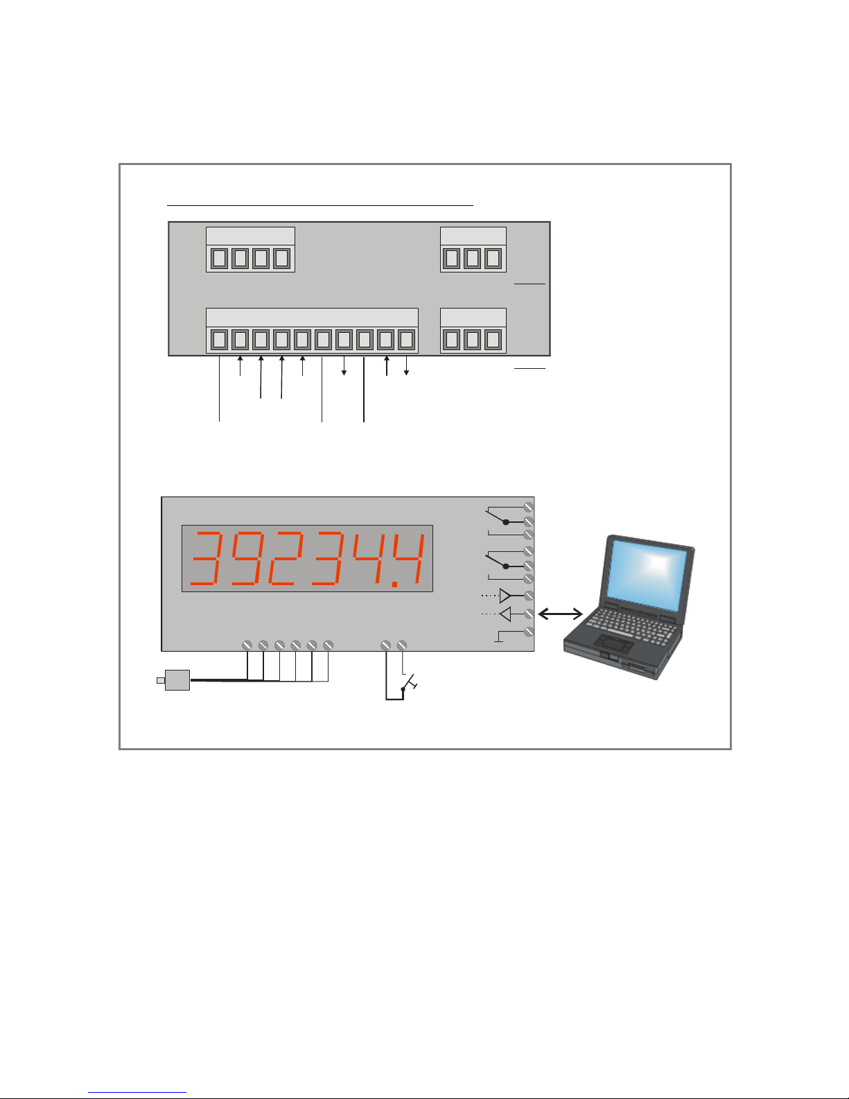
1. Terminal Assignment
Terminal Assignment and Connection Example
GND
17-30VCDIN
12345678910
INPUTA
INPUTB
RESET(C)
+24VDCOUT
TXD/B(-)
RXD/A(+)
GND
GND
123
123
X1 X2
X3
C NO NC
C NO NC Rel. 1
Rel. 2
X4
1234
CLK+
CLK-
DAT+
DAT-
Rel. 2
Rel. 1
TxD
RxD
GND
SSI Absolute Encoder Set / Reset
+
-
Clock+
Clock-
Data+
Data-
C
NC
NO
C
NC
NO
*)
RS232
*) Contact positions in power-down state of the unit
IX34208a_e.doc / Aug-09 Page 5 / 40
1.1. Power Supply
The unit accepts DC supply from 17 to 30 VDC which must be applied to terminals 1 and 2.
The current consumption depends on the level of the supply voltage and is typically 130mA at
30V or 190mA at 17V, plus currents taken from aux. output).
1.2. Aux. Voltage Output
Terminal 7 provides an auxiliary output of 24 VDC / 120 mA (+/-15%) for supply of sensors and
encoders.
1.3. Control Inputs A, B and Reset ( C )
Standard units use only input “C” as a Reset input and the other inputs are out of function.
In the basic setup menu the inputs can be configured to PNP (signal must switch to +) or to NPN
(signal must switch to -). This configuration is valid for all three inputs at a time.
The factory setting is always PNP.
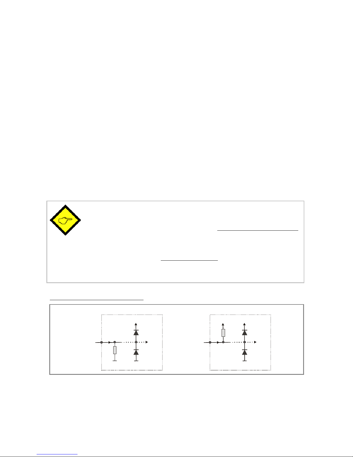
xIndependent of your setting, all functions of the unit are “active HIGH“ and
the unit triggers to positive transitions (rising edge). Because with NPN
setting open or unused inputs are HIGH, you must tie the Reset line to GND
for operation. Otherwise your unit will be in a continuous RESET state and
cannot work.
xWhere your use 2-wire NAMUR type sensors, please select NPN, connect
the negative wire of the sensor to GND and the positive wire to the
corresponding input.
Typical input circuit of control input
PNP
4,7k
GND GND
+24V int.
Input
4,7k
GND
Input
+24V int.
NPN
The minimum pulse duration on the Reset input (C) must be 5 msec.

IX34208a_e.doc / Aug-09 Page 6 / 40
1.4. Relay Outputs
The unit provides two presets with relay outputs (dry change-over), each with a switching
capability of 250 VAC / 1A / 250 VA or 100 VDC / 1A / 100 W respectively.
The response time of the relays is approx. 10 msec.
In case of switching inductive loads it is advisable to use external filtering of the coils.
1.5. Serial RS232 / RS485 interface
Ex factory the unit is set to RS232 communication. This setting can be changed to RS485
(2-wire) by means of an internal DIL switch. To access the DIL switch, you must remove the
screw terminal connectors and the backplane. Then pull the board to the rear to remove the
PCB from the housing.
ON DIP
DIL-Switch
Removal of the back plane Location of the DIL switch
RS232:
ON
8
9
10
RxD
TxD
GND
RS485:
ON
8
9
10
A (+)
B (-)
GND
xNever set DIL switch positions 1 and 2 or DIL switch positions 3 and 4 to
“ON” at the same time!
xAfter setting the switch, shift the print carefully back to the housing and
avoid damage of the front pins for connection to the front keypad plate.

IX34208a_e.doc / Aug-09 Page 7 / 40
2. How to Operate the Front Keys
For setup and other operations the unit uses three front keys which subsequently will be
denominated as follows:
«
ENTER
(Input)
SET
(Setting)
Cmd
(Command)
The functions of the keys are depending on the actual operating state of the unit.
The following three operating states apply:
xNormal display state
xSetup state
a.) Basic setup
b.) Operational parameter setup
xTeach operation
2.1. Normal display state
You can only change over to other operation states while the unit is in the
normal display state.
Change over to Key operation
Basic setup Keep E
E
NTER and S
S
ET down simultaneously for 3 seconds
Operational
parameter setup
Keep E
E
NTER down for 3 seconds.
Teach operation Keep C
C
md down for 3 seconds
The Cmd key is only used to execute the Teach procedure with linearization. For more details
please refer to sections 6.1 and 6.2.

IX34208a_e.doc / Aug-09 Page 8 / 40
2.2. Selection and Setting of Parameters
2.2.1. How to select a parameter
The E
E
NTER key will scroll through the menu. The S
S
ET key allows to select the corresponding
item and to change the setting or the numeric value. After this, the selection can be stored by
ENTER again, which automatically changes over to the next menu item.
2.2.2. How to change parameter settings
With numerical entries, at first the lowest digit will blink. When keeping the S
S
ET key
continuously down, the highlighted digit will scroll in a continuous loop from 0 … 9 , 0 … 9.
After releasing the S
S
ET key, the actual value will remain and the next digit will be highlighted
(blink). This procedure allows setting of all digits to the desired values. After the most
significant digit has been set, the low order digit will blink again and you can do corrections if
necessary.
With signed parameters, the high order digit will scroll from “0” to "9" (positive) followed by
“-“ and "-1" (negative)
2.2.3. How to store settings
To store the actual setting, press the E
E
NTER key, which will also automatically scroll forward
the menu.
At any time the unit changes from programming mode to normal display operation, when you
keep the E
E
NTER key down again for at least 3 seconds.
2.2.4. Time-out function
A “time-out” function will automatically conclude every menu level, when for a break period of
10 seconds no key has been touched. In this case, any changes which have not been confirmed
by E
E
NTER yet would remain unconsidered.

IX34208a_e.doc / Aug-09 Page 9 / 40
2.3. Teach operation
The Time-out function will be switched off during all Teach operations
Key Function
«
ENTER will conclude or abort any Teach operation in progress
SET function is fully similar to normal set-up operation
Cmd will store the display value to the register and will change over to the
next interpolation point.
For details of the Teach procedure see section 6.2.
2.4. Set all parameters to “Default“
At any time you can return all settings to the factory default values.
The factory default settings are shown in the parameter listings in section 6.
When you decide to set all parameters to „default“, please be aware that all
previous settings will be lost and you will need to do the whole set-up
procedure once more
To execute the „Default“ setting function:
xPower the unit down.
xPress the ENTER key.
xPower the unit up again while the ENTER key is kept down
2.5. Code Locking of the Keypad
When the code locking of the keypad has been switched on, any key access first results in
display of
To access the menu you must press the key sequence
«
«
«
within 10 seconds, otherwise the unit will automatically return to the normal display mode.

IX34208a_e.doc / Aug-09 Page 10 / 40
3. The Operator Menu
The menu provides one section with “Basic Parameters” and another section with “Operational
Parameters”. On the display you will only find those parameters which have been enabled by
the basic settings. E.g. when the Linearisation Functions have been disabled in the basic set-
up, the associated linearization parameters will also not appear in the parameter menu.
All parameters, as good as possible, are designated by text fragments. Even though the
possibilities of forming texts are very limited with a 7-segment display, this method has proved
to be most suitable for simplification of the programming procedure.
The subsequent table shows the general structure of the whole menu only.
Detailed descriptions of all parameters will follow in section 4.
3.1. Overview of Basic Parameters
General: SSI_Mode
SSI_Bits
SSI_Format
SSI_Baudrate
SSI_Test
Characteristics
Brightness
Code Interlock
Mode of Linearization
Presets and relays: Preset_Mode 1
Preset_Mode 2
Hysteresis 1
Hysteresis 2
Serial Interface Ser_Unit_Nr
Ser_Format
Ser_Baudrate

IX34208a_e.doc / Aug-09 Page 11 / 40
3.2. Overview of Operational Parameters
Presets: Preselection 1
Preselection 2
Display and Scaling: M-Factor
D-Factor
P-Factor
Decimal point
Display
Hi_Bit (MSB)
Lo_Bit (LSB)
Direction
Error
Error_Polarity
Round loop
Time
Reset
Zero Position
Serial Interface: Ser_Timer
Ser_Mode
Ser_Val
Linearization: P01_X *)
P01_Y*)
Æ
P16_X *)
P16_Y *)
*) appears only when Linearization has been enabled in the Basic Menu

IX34208a_e.doc / Aug-09 Page 12 / 40
4. Setup Procedure
For better understanding the following sections 4.1 and 4.2 explain settings for the display only.
Settings for Preselections and Serial Link will be explained separately, later.
4.1. Basic Parameters
The subsequent settings are of unique nature and must only be made upon the very first setup.
The basic setup selects the desired operation mode of the unit, the input characteristics
PNP/NPN and the desired brightness of the LED display.
Menu Setting Range Default
SSI-Mode
Setting of Master Mode or Slave Mode
For details see section 5.1
SSI-Bits
Bit length of the SSI string
For details see section 5.2
For word lengths other than 13, 21 or 25 select the
next higher setting
(e.g. set 21 bits with use of a 16 bit encoder)
SSI-Format:
Setting of the SSI code (Binary or Gray)
SSI-Baud Rate 0.1 ... 1000.9
kHz
100.0
kHz
SSI Test
SSI Self test functions (see 5.5.)
0 ... 8 0
0
Characteristics
Switching characteristics of the Reset input
NPN: switch to "-"
PNP: switch to "+"
Brightness 100%
Brightness of the 7-segment LED display
20%, 40%, 60%
80% and 100%

IX34208a_e.doc / Aug-09 Page 13 / 40
Menu Setting Range Default
Code Locking
Interlock of keypad access (see 2.5)
no: Keypad accessible at any time
All: Keypad interlock for all functions
P-Free: Keypad interlock except for Preselection
Settings Pres 1 und Pres 2
Linearization Mode
For details please see 6.1 und 6.2.
no: Linearization is switched OFF *)
1-qua: Linearization settings for the positive range
only (negative values will appear as a mirror).
4-qua: Linearization over the full numeric range
*) The menu will not display any further linearization parameters
IX34208a_e.doc / Aug-09 Page 14 / 40
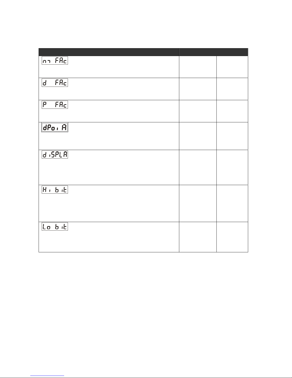
4.2. Operational Parameters
Menu Setting Range Default
M-Factor *):
Multiplying factor for the SSI value
(after consideration of possible bit blanking)
-9.999 … 9.999 1
1
.000
D-Factor *):
Dividing factor for the SSI value
(after consideration of possible bit blanking)
0.001 … 9.999 1
1
.000
P-Factor *):
This signed value will be added to the SSI result
(after consideration of possible bit blanking)
-199999
…
999999
0
Decimal Point
Setting according to the decimal formats shown in
the display
000000
00000.0
...
0.00000
00000.0
Display:
Display mode of the unit
norm: regular scaling of the display
359.59: Angular display format 359° 59' with use of
the Round Loop Function
norm
359.59
norm
Hi Bit **): 1 … 25 2
2
5
Bit Blanking Function: Defines the highest bit for
evaluation. To evaluate all encoder bits this
parameter has to be set to the total number of bits
according to setting (13, 21, 25)
Lo Bit **): 1 … 25 1
1
Bit Blanking Function: Defines the lowest bit for
evaluation. To evaluate all encoder bits this
parameter has to be set to "01"
*) Scaling details are explained under 5.3
**) For more details about Bit Blanking see 5.2
IX34208a_e.doc / Aug-09 Page 15 / 40
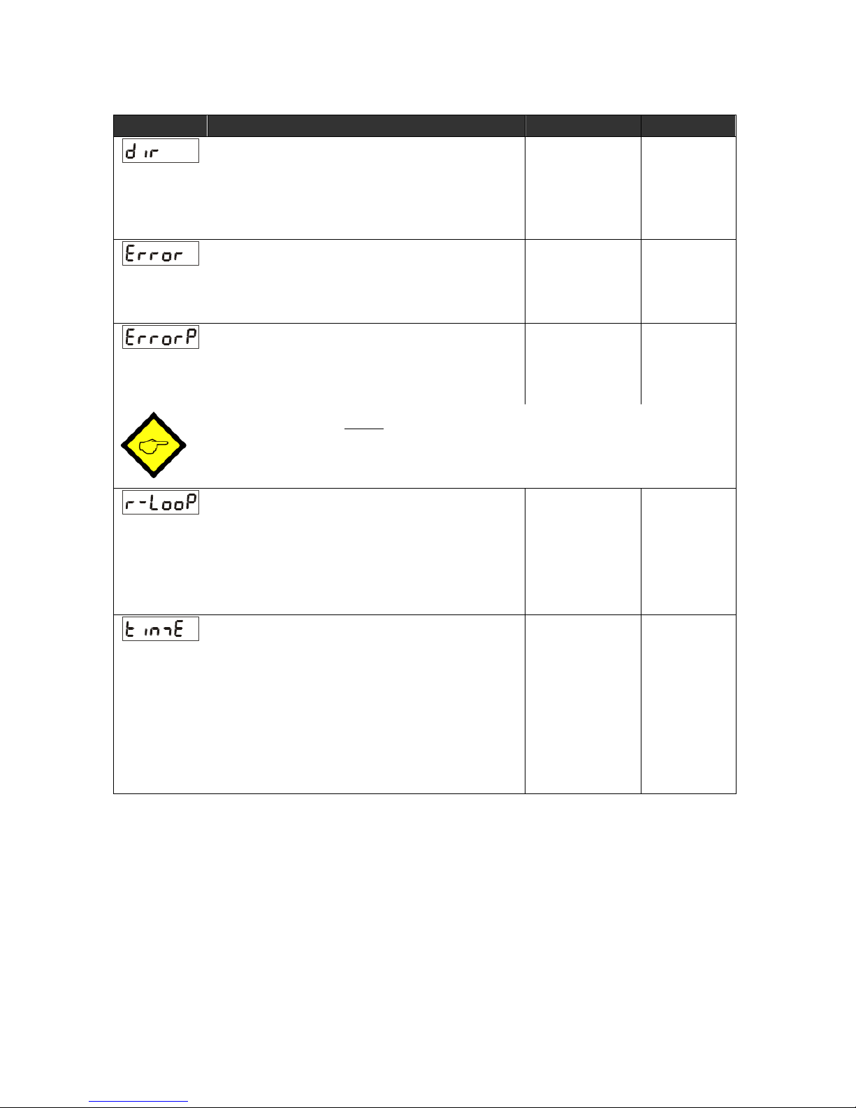
Menu Setting Range Default
Direction
Parameter to negate the SSI value, resulting in
reversal of the direction of the encoder count.
riGht: ascending values with forward motion
LEFt:: decreasing values with forward motion
riGht
LEFt
riGht
Error
Defines the location of the Error Bit
0: no Error Bit available
01 - 25: Location of the Error Bit
0 ... 25 0
0
Error-Polarity *):
Defines the polarity of the Error Bit in case of error.
0: Error Bit is Low in case of error
1: Error bit is High in case of error
0
1
0
When an error occurs, „
„
Err-b“ appears on the display.
The same function can also be used to monitor the Power Failure Bit of an encoder
(mostly called „PFB“).
Round Loop
Defines the number of encoder steps per revolution
with use of the Round Loop Function (see 5.4.2).
0: Normal display of the encoder data, no
Round Loop Function
>0: Number of steps per Round Loop Cycle
0 ... 999999 0
0
Time
Sets the update cycle of the display (and of the
analogue output or the switching outputs where
applicable). The fastest possible update time is
3 msec. respectively one telegram length including 4
pause clocks. With Slave operation the next update
will occur when the unit synchronizes again to the
Master pause following to the expiration of the
update time.
0.000 ... 1.009
sec
0.01 sec
IX34208a_e.doc / Aug-09 Page 16 / 40
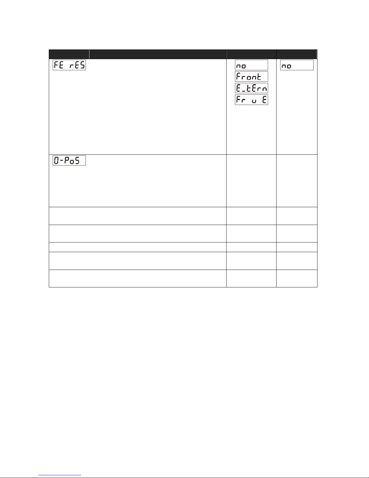
Menu Setting Range Default
Reset
A Reset command is available to store the actual SSI
position to register „Zero Position“. As a result, the
display value will become zero at the actual encoder
position, and all further operation will refer to this
new datum point. The zero position remains
memorized also after power-down.
no: Reset function disabled
Front: Reset function by the front SET key
E_tErn: Reset function by the remote Reset input
FR u E: Reset via key and remote input
Zero Position: *)
Defines the zero position of the display. When you
set this parameter to e.g. "1024", the unit will
display zero when the encoder position is 1024.
Zero Position can be set directly via keypad or by
means of an external Reset command.
-199999
...
999999
0
P01_X **) L
L
inearization Point 1_X
X value of the first interpolation point.
-199999
... 999999
999999
P01_Y Linearization Point 1_Y
Y value of the first interpolation point.
-199999
... 999999
999999
…
P16_X Linearization Point 16_X
X value of the 16. interpolation point.
-199999
... 999999
999999
P16_Y Linearization Point 16_Y
Y value of the 16. interpolation point.
-199999
... 999999
999999
*) Please observe that Parameter P_Fac will cause an additional displacement of the zero position
**) Parameters P01_X to P16_Y appear only when the linearization has been enabled in the basic menu

IX34208a_e.doc / Aug-09 Page 17 / 40
4.3. Parameters for Preselections and Relay Outputs
The following additional settings for the Preselections appear in the Basic Menu:
Menu Default
Switching Characteristics of Relay 1
Greater/Equal. Relay to switch statically ON
when Display Value Preselection1
Lower/Equal. Relay to switch statically ON
when Display Value Preselection1
Greater/Equal. Relay to switch dynamically ON
when Display Value Preselection1
(timed output pulse) *)
Lower/Equal. Relay to switch dynamically ON
when Display Value Preselection1
(timed output pulse) *)
Switching Characteristics of Relay 2
See above, but Preselection2
See above, but Preselection2
See above, but Preselection2
See above, but Preselection2
Relay to switch statically ON when
Display Value Preselection1 – Preselection2 **)
Relay to switch dynamically ON when
Display Value Preselection1 – Preselection2 **)
HYSt 1 Hysteresis 1
Adjustable hysteresis for Relay 1
Setting range 0 ... 99999 display units
0
HYSt 2 Hysteresis 2
Adjustable hysteresis for Relay 2
Setting range 0 ... 99999 display units
0
*) Timed output pulses have a fixed duration of 500 msec (factory adjustable only)
**) Trailing Preset to generate an anticipation signal with a fixed distance to the main signal
IX34208a_e.doc / Aug-09 Page 18 / 40
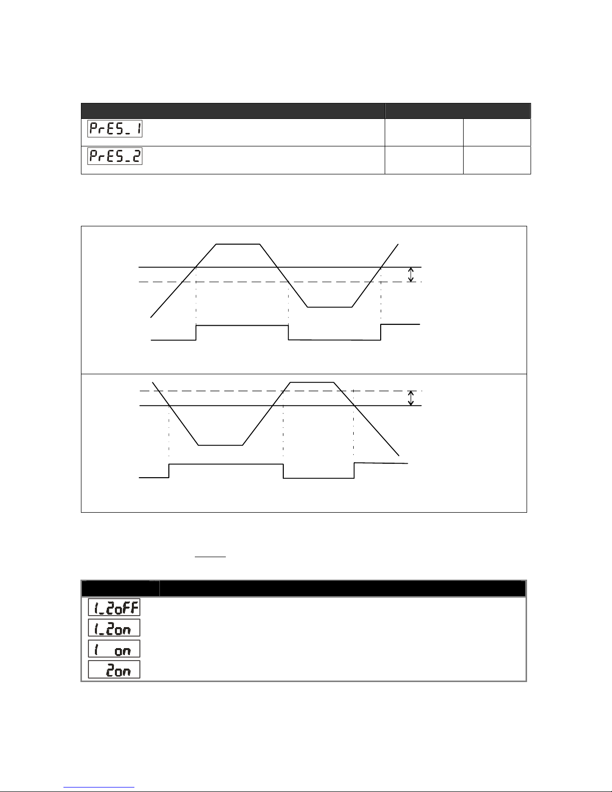
The following Operational Parameters provide setting of the switching thresholds:
Menu Setting Range Default
Preselection 1: -199999..
999999
10000
Preselection 2: -199999..
999999
5000
The direction of the Hysteresis effect depends on the setting of the switching characteristics.
With the settings „GE“ or „LE“ the following switch points will result:
Preselection
Hysteresis
GE=Greater/Equal
Display Value
Hysteresis effect with "Greater / Equal"
Preselection
LE=Lower/Equal
Hysteresis
Display Value
Hysteresis effect with "Lower / Equal"
It is possible to check up on the actual switching state of the relays at any time.
For this, just tap on the ENTER key shortly.
The display will then show for the next two seconds one of the following information:
Display Meaning
Both relays are actually OFF
Both relays are actually ON
Relay 1 is ON Relay 2 is OFF
Relay1 is OFF Relay 2 is ON
IX34208a_e.doc / Aug-09 Page 19 / 40
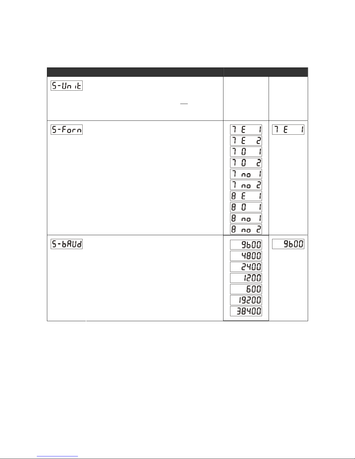
4.4. Parameters for Setup of the Serial Interface
The following additional settings for serial communications appear in the Basic Menu:
Menu Setting Range Default
Unit Number
You can assign any unit number between
11 and 99. The address must however not contain a
“0“ because such numbers are reserved for collective
addressing of several units.
0..99 1
1
1
Serial Data Format
The first character indicates the number of data bits.
The second character specifies the Parity Bit
„Even“, "Odd“ or no Parity Bit.
The third character indicates the number of Stop Bits.
Baud Rate
The following Baud Rates can be set for
communication:
IX34208a_e.doc / Aug-09 Page 20 / 40
The following Operational Parameters provide configuration of the serial interface:
Menu Setting Range Default
Serial Timer:
Setting 0,000 allows manual activation of a serial data
transmission at any time. All other settings specify the cycle
time for automatic transmission, when the interface is set to
"Printer Mode"
0,000
0,010 sec
…
9.999 sec
0,100 sec
Between two transmission cycles the unit will allow a pause
depending on the baud rate. The minimum cycle times for
timer transmissions are shown in the table.
Baud Rate Minimum Cycle Time [ms]
600 384
1200 192
2400 96
4800 48
9600 24
19200 12
38400 6
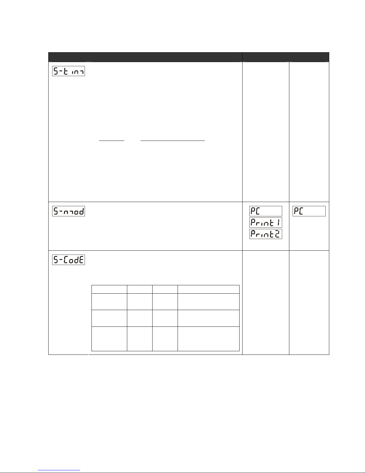
Serial Mode:
PC: Operation according to communication profile
(see 4.4.1)
Print1: Transmission of string type 1 (see 4.4.2)
Print2: Transmission of string type 2 (see 4.4.2)
Serial Register-Code: 101
Specifies the register code of the data to be transmitted.
The most important register codes are:
Register S-Code ASCII Description
Original SSI
Value
111 ;
;
1 Direct encoder data
SSI Value 113 ;
;
3 Encoder data after
Bit Blanking
Display
value
101 :
:
1 Value with full scaling
as it appears in the
display
100
...
120
Table of contents
Other Motrona Touch Panel manuals


 quick start guide")
