Motrona CA340 User manual
Operating Manual
CA340 and CA541
Process value and parameter indicators for CAN-Bus
Product Features:
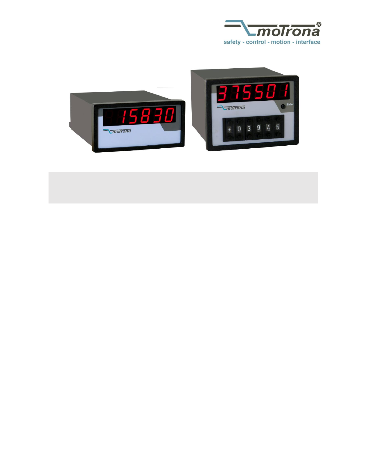
The CA340 variant is a simple indicator unit for remote display of all actual data which
are available on the connected CAN-Bus network. Arbitrary parameters or actual values
can be read or displayed.
CA541 is a combination of preset switch and indicator. While the BCD switch allows to
make register changes via CAN-Bus, the LED display provides information about the
actual setting of the same or any other register value.
Available Devices:
CA340: Display unit only
CA541: Display / Preset combination (SDO / PDO switchable)
3046 Home Road. Powell, OH 43065 P: (740) 917-5781 F: (740) 917-5791 www.GenesisAutomationOnline.com [email protected]
www.GenesisAutomationOnline.com

Ca340_03b_oi_e.doc / Apr-16 Page 2 / 15
Version:
Description:
Ca340_01a …03a
Diverse version updates
Ca340_03b_oi/Nov-11/ag
Safety instructions and legal Notices supplemented. Specifications updated.
Dual language version separated in two stand-alone versions.
Legal notices:
All contents included in this manual are protected by the terms of use and copyrights of motrona GmbH. Any
reproduction, modification, usage or publication in other electronic and printed media as well as in the internet
requires prior written authorization by motrona GmbH.
Table of Contents
1. Safety Instructions and Responsibility ......................................................... 3
1.1. General Safety Instructions......................................................................................3
1.2. Use according to the intended purpose ...................................................................3
1.3. Installation................................................................................................................4
1.4. Cleaning, Maintenance and Service Notes .............................................................4
2. Allgemeines ................................................................................................ 5
3. Block diagram.............................................................................................. 5
4. Connections................................................................................................. 6
5. Setting of the network Baud rate and sign................................................... 7
6. Setting of unit address and transmission mode ........................................... 8
7. Data transmission by SDO (Service Data Object) ......................................... 9
8. Datenübertragung als Prozessdaten mit PDO (Process Data Object)........... 11
9. Error Messages ......................................................................................... 14
10. Dimensions................................................................................................ 14
11. Technical Specifications ............................................................................ 15

Ca340_03b_oi_e.doc / Apr-16 Page 3 / 15
1. Safety Instructions and Responsibility
1.1. General Safety Instructions
This operation manual is a significant component of the unit and includes important rules and
hints about the installation, function and usage. Non-observance can result in damage and/or
impairment of the functions to the unit or the machine or even in injury to persons using the
equipment!
Please read the following instructions carefully before operating the device and observe all
safety and warning instructions! Keep the manual for later use.
A pertinent qualification of the respective staff is a fundamental requirement in order to use
these manual. The unit must be installed, connected and put into operation by a qualified
electrician.
Liability exclusion: The manufacturer is not liable for personal injury and/or damage to property
and for consequential damage, due to incorrect handling, installation and operation. Further
claims, due to errors in the operation manual as well as misinterpretations are excluded from
liability.
In addition the manufacturer reserve the right to modify the hardware, software or operation
manual at any time and without prior notice. Therefore, there might be minor differences
between the unit and the descriptions in operation manual.
The raiser respectively positioner is exclusively responsible for the safety of the system and
equipment where the unit will be integrated.
During installation or maintenance all general and also all country- and application-specific
safety rules and standards must be observed.
If the device is used in processes, where a failure or faulty operation could damage the system
or injure persons, appropriate precautions to avoid such consequences must be taken.
1.2. Use according to the intended purpose
The unit is intended exclusively for use in industrial machines, constructions and systems. Non-
conforming usage does not correspond to the provisions and lies within the sole responsibility
of the user. The manufacturer is not liable for damages which has arisen through unsuitable
and improper use.
Please note that device may only be installed in proper form and used in a technically perfect
condition (in accordance to the Technical Specifications, see chapter 11).
The device is not suitable for operation in explosion-proof areas or areas which are excluded by
the EN 61010-1 standard.

Ca340_03b_oi_e.doc / Apr-16 Page 4 / 15
1.3. Installation
The device is only allowed to be installed and operated within the permissible temperature
range. Please ensure an adequate ventilation and avoid all direct contact between the device
and hot or aggressive gases and liquids.
Before installation or maintenance, the unit must be disconnected from all voltage-sources.
Further it must be ensured that no danger can arise by touching the disconnected voltage-
sources.
Devices which are supplied by AC-voltages, must be connected exclusively by switches,
respectively circuit-breakers with the low voltage network. The switch or circuit-breaker must
be placed as near as possible to the device and further indicated as separator.
Incoming as well as outgoing wires and wires for extra low voltages (ELV) must be separated
from dangerous electrical cables (SELV circuits) by using a double resp. increased isolation.
All selected wires and isolations must be conform to the provided voltage- and temperature-
ranges. Further all country- and application-specific standards, which are relevant for structure,
form and quality of the wires, must be ensured. Indications about the permissible wire cross-
sections for wiring are described in the Technical Specifications (see chapter 11).
Before first start-up it must be ensured that all connections and wires are firmly seated and
secured in the screw terminals. All (inclusively unused) terminals must be fastened by turning
the relevant screws clockwise up to the stop.
Overvoltages at the connections must be limited to values in accordance to the overvoltage
category II.
For placement, wiring, environmental conditions as well as shielding and earthing/grounding of
the supply lines the general standards of industrial automation industry and the specific
shielding instructions of the manufacturer are valid.
Please find all respective hints and rules on www.motrona.com/download.html
--> “[General EMC Rules for Wiring, Screening and Earthing]”.
1.4. Cleaning, Maintenance and Service Notes
To clean the front of the unit please use only a slightly damp (not wet!), soft cloth. For the rear
no cleaning is necessary. For an unscheduled, individual cleaning of the rear the maintenance
staff or assembler is self-responsible.
During normal operation no maintenance is necessary. In case of unexpected problems, failures
or malfunctions the device must be shipped for back to the manufacturer for checking,
adjustment and reparation (if necessary). Unauthorized opening and repairing can have
negative effects or failures to the protection-measures of the unit.
Ca340_03b_oi_e.doc / Apr-16 Page 5 / 15
2. Introduction
The CA340/541 display units have been designed to display single parameters or registers (like
position or speed) in systems using a CANopen network for communication. CA541 also allows
remote setting of a single parameter.
CA340 serves as pure readout unit without preset functions. Both units are built into a
DIN housing and have a 6 decade, 15mm size LED-display.
CA541 additionally includes a 6 digit BCD thumbwheel switch (Preset range 0...999 999).
With supplementary ordering information Option VZ000, the unit is supplied in a
“5 digit plus sign”version (preset range: -99 999 …0 …+99 999).
With both units, data can be transmitted as service data (SDO), accessing adjustable register
codes of a network participant, or as process data (PDO).
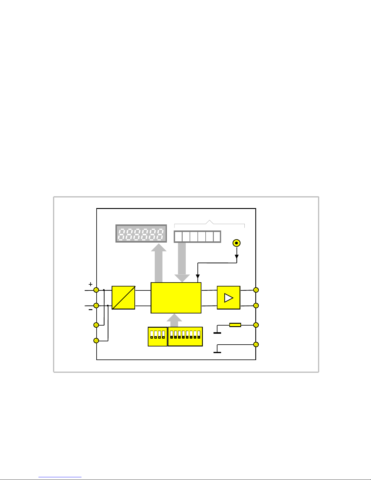
3. Block diagram
12 34 1 2345678
ENTER
Potential
Separation
DC
DC
Power
10...35VCD
CAN
Driver
100R
CAN high
CAN low
GND (100R)
GND
(C+)
(C-)
(G)
(GND)
12position DILswitch
BCD Data
3 4 521 6
Display
Processor and
CAN controller
CA541
Ca340_03b_oi_e.doc / Apr-16 Page 6 / 15
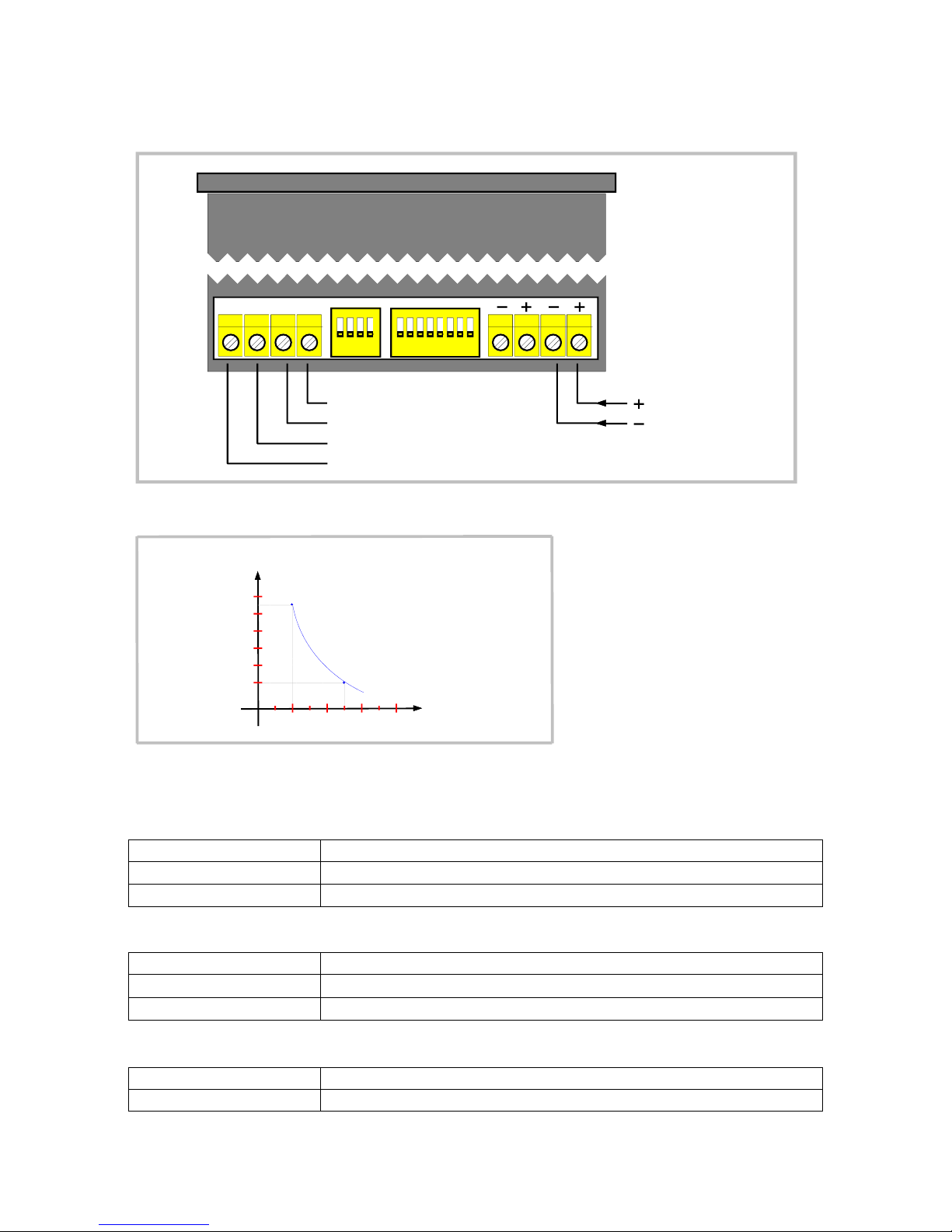
4. Connections
Screw terminals and DIL switches for setup are located on the backplane of the unit:
12 34 123 4567 8
GND GC- C+
CAN high
CAN low
GND (100R)
GND
10...35V
Power Supply
Current consumption, depending on supply voltage:
160
140
120
100
80
60
10 20 30 40
mA
Volt
The following cables are recommended for CAN communication, depending on the cable length:
Up to 300 meters:
Cable type
LIYCY 2 x 2 x 0,5 mm² (twisted and screened)
Resistance
40 /km
Capacity
130 nF/km
More than 300 meters:
Cable type
CYPIMF 2 x 2 x 0,5 mm² (twisted and screened)
Resistance
40 /km
Capacity
60 nF/km
Please use the leads like shown:
Pair 1 (white/brown)
CAN-Low and CAN-High
Pair 2 (green/yellow)
GND

Ca340_03b_oi_e.doc / Apr-16 Page 7 / 15
Both extreme ends of the CAN network must be terminated by a 120 Ohms resistor. The shield
must be connected to earth potential.
120Ohms120Ohms
Schirm/
CAN+ CAN- GND CAN+ CAN- GNDCAN+ CAN- GND
Erster Busteilnehmer
First network participant Last network participant
Letzter Busteilnehmer
Shield
5. Setting of the network Baud rate and sign
Depending on the Baud rate, the following maximum cable length must not be exceeded:
maximum cable length
Baud rate (kbit / s)
50
125
250
500
1000
Cable length (m)
1000
550
250
110
25
Setting the baud rate uses positions 1 to 3 of the 4-position DIL switch on the rear:
412 3 1 2 3 4 5 6 78
GND GC- C+
00 0
10 0
01 0
1
1 1
11111
11 0
000
0
=
=
=
=
=
=
=
=
Baud
Baud
Baud
Baud
Baud
Baud
Baud
Baud
1000k
500k
250k
125k
50k
20k
10k
10k
412 3
"0"
"1" =
=OFF
ON
ON
OFF
Beispiel
Example :
:500kBaud
Ca340_03b_oi_e.doc / Apr-16 Page 8 / 15
Slider 4 defines the most significant digit of the front thumbwheel switches to be transmitted
as a number or a sign (CA541 only):
4123
ON
OFF
ON
OFF OFF: 0...9 4123
ON: +/-
The version with a sign (option VZ000) requires slider 4 to be “ON“ at any time!
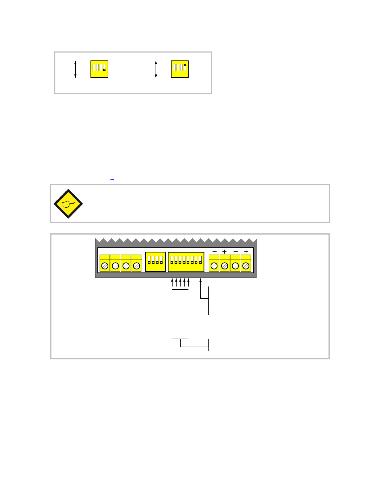
6. Setting of unit address and transmission mode
Sliders 1-5 of the 8-position DIL switch select the unit address (01-31).
Slider 8 determines the CANopen transmission mode: Set to OFF, data is transmitted by SDO
(Service Data Object, see chapter 7). Set to ON, data is transmitted by PDO (Process Data
Object, see chapter 8).
Important note: All DIL switch settings are only read upon initialization and
changes during normal operation will not be recognized! After change of DIL
switch settings, the unit must be powered up again!
4123 12345678
GND GC- C+
CANopen Übertragungsart:
CANopen transmissionmode:
Geräteadresse 00-31
Deviceaddress 00-31
00100
10000
01000
11000
11111
.
:
0 : SDO (Service DataObject)
1 : PDO (Process DataObject)
04 :
01 :
02 :
03 :
31 :

Ca340_03b_oi_e.doc / Apr-16 Page 9 / 15
7. Data transmission by SDO (Service Data Object)
[DIL switch slider 8 = OFF]
The unit requests the display value by an SDO (Service Data Object) read request and transmits
the preset value (CA541 only) by an SDO write request. Within the next 2.5 sec (Timeout) a
corresponding read or write response is awaited.
The unit operates similar to a CANopen master (But it is not a master!). There-fore, the
selected unit address must match with the target device. No other CANopen communication
objects are supported, except the SDOs.
Transmit SDO:
Identifier: Data-
Byte 0 Data-
Byte 1 Data-
Byte 2 Data-
Byte 3 Data-
Byte 4 Data-
Byte 7
Data-
Byte 5
Command
specifier: (low) Index (high): Sub-
Data-
Byte 6
(low) (high)32Bit data
Write request (= 5FFFh - Code) Index
40h=
Read request
1536 (600h) +
unit adress
SDO1:
1600 (640h) +
unit adress
SDO2: 23h=
Receive SDO:
Identifier: Data-
Byte 0 Data-
Byte 1 Data-
Byte 2 Data-
Byte 3 Data-
Byte 4 Data-
Byte 7
Data-
Byte 5
Command
specifier: (low) Index (high): Sub-
Data-
Byte 6
(low) (high)32Bit data
(= 5FFFh - Code) Index1408 (580h) +
unit adress
SDO1:
1472 (5C0h) +
unit adress
SDO2: Write response
4xh=
Read response
60h=
The register codes to be accessed in the target unit refer to LENZE series 9300 drives. Other
code classifications are possible on demand at any time.
Slider 7 of the 8-position DIL switch selects transmission of data on parameter channel 1 (SDO
1) or parameter channel 2 (SDO 2). Thus it is possible to connect two display units to one target
unit without disturbing each other (Version CA34002A and later).

Ca340_03b_oi_e.doc / Apr-16 Page 10 / 15
The code of the register to be displayed and the code of the register to be Set are requested
from register code 473 of the target unit. When transmitting on parameter channel 1 (SDO1)
Subcode 3...6 is used, transmitting on parameter channel 2 (SDO2) Subcode 7...10 is used.
Therefore, it is possible to display respectively to preset two different values of one target
device by using two display units running on different parameter channels (Version CA34002A
and later).
The values of register code 473 have to be organized like shown in the following table:
Subcode 5 (SDO1) / Subcode 9 (SDO2):
Code of register to be displayed
Subcode 6 (SDO1) / Subcode 10 (SDO2):
1. figure = 0: Display value without factor
n: Display value x 10 000
(Lenze data type FIX32)
n-1: decimal places are displayed**
2./3. figure = Display update time (x 100 ms)
4./5. figure = Subcode of display value
Subcode 3 (SDO1) / Subcode 7 (SDO2):
Code of register to be preset (only CA541)
Subcode 4 (SDO1) / Subcode 8 (SDO2):
1. figure = 0: Preset value without factor
1: Preset value x 10 000
(Lenze data type FIX32)
4./5. figure = Subcode of register to be preset
*) Register Code 473 is limited to +/-32768. Therefore a maximum of 2 decimal places can be
displayed.
Example: You want to display register Code 472 / Subcode 19. That register contains 4 decimal
places ( x10 000), but you want to display only 2 decimal places. The display value shall be
transmitted on parameter channel 2 with an update time of 500 ms..
This results in the following settings of register 473:
C 473 / 9 = 00472
C 473 / 10 = 30519
Where register code 473 contains invalid values, initialization will canceled off and error
message E 016 will appear.

Ca340_03b_oi_e.doc / Apr-16 Page 11 / 15
With the CA541, Position 6 of the 8-position DIL switch selects only temporary use of transmit
data in the target device (no storage to EEPROM), or continuous use even after power down
(nonvolatile storage to EEPROM by setting register Code C003 “Par. Save” to 1 after transmitting
the value).
412 3 1 2 3 4 5 6 7 8
GND GC- C+
ohneSpeicherung imEEProm0: nostorage toEEprom
mit Speicherung im EEProm
storage toEEprom
1:
Parameterkanal 2 (SDO 2)0: Parameter channel 2 (SDO 2)
Parameterkanal 1 (SDO 1)1: Parameter channel 1 (SDO 1)
(Ab Version CA34002A)
(VersionCA34002A andlater)
8. Datenübertragung als Prozessdaten mit PDO (Process Data Object)
[DIL switch slider 8 = ON]
The unit operates like a CANopen device corresponding to CiA DS 301 V4.01.
The unit receives the display value and transmits the BCD value (CA541 only) as 32 bit-data by
PDOs (Process Data Objects).
After power on the unit enters CANopen state “Initialising”. After successful initialization, the
unit enters state “Pre-Operational”. Now the unit is ready for CANopen communication and
sends a Bootup-Message to the CANopen master:
Identifier: Data-Byte 0
1792 (700h) + unit address 0
To start the PDO communication the NMT (Network management) message “Start Remote
Node” has to be sent by the CANopen master device:
Identifier: Data-Byte 0
0 (NMT) 01
(Command specifier
"Start Remote Node")
Data-Byte 1
Geräteadresse
00 (Alle Geräte)
unit adress
oder or
00 (all units)
By that means the unit enters CANopen state „Operational“ and is ready for PDO data exchange.

Ca340_03b_oi_e.doc / Apr-16 Page 12 / 15
Receive PDO:
Identifier: Data-
Byte 0 Data-
Byte 1 Data-
Byte 2 Data-
Byte 3 Data-
Byte 4 Data-
Byte 7
Data-
Byte 5 Data-
Byte 6
(low) (high)32 bit display datasynchronous:
512 (200h) + unit address (DIL switch pos. 7 = OFF)
(low) (high)32 bit display data
(DIL switch pos. 7 = ON)asynchronous:
768 (300h) + unit address
Transmit PDO:
Identifier: Data-
Byte 0 Data-
Byte 1 Data-
Byte 2 Data-
Byte 3 Data-
Byte 4 Data-
Byte 7
Data-
Byte 5 Data-
Byte 6
(low) (high)32 bit BCD datasynchronous:
384 (180h) + unit address (DIL switch pos. 7 = OFF)
(low) (high)32 bit BCD data
(DIL switch pos. 7 = ON)asynchronous:
640 (280h) + unit address
Slider 6 of the 8-position DIL switch selects asynchronous or synchronous PDO transmission.
Asynchronous PDO transmission: The display value will be displayed immediately after
reception of the corresponding PDO. The CA541 BCD data will be transmitted
immediately after the pressing the Enter-button.
Synchronous PDO transmission: The display value received by PDO will only be
displayed after reception of SYNC message sent by the master. The CA541 BCD data is
latched when pressing the Enter-button and transmitted after reception of SYNC-
Message.
Slider 7 allocates the display- and BCD-value to the lower or higher section of the PDO data bytes.
4123 1 23456 78
GND GC- C+
DataByte 0...3
DataByte 4...7
Übertragung synchron (PDO 1)0: Synchronous transmission (PDO 1)
Übertragung asynchron (PDO 2)1: Aynchronous transmission (PDO 2)
0:
1:

Ca340_03b_oi_e.doc / Apr-16 Page 13 / 15
Decimal Place: If required, a decimal point can be set by SDO with index 5100hex / Subindex 0
(number of decimal places). However, the value will not be stored to non-volatile memory.
Therefore the number of decimal places must be re-set on every power on.
Node Guarding: The CA340/CA541 provides CANopen Node Guarding. By this function the
master can supervise the unit and detect any device breakdown.
The master can request a Node Guarding Message by sending a RTR (Remote Transmit
Request) with the corresponding identifier to the slave unit.
Node Guarding request by master:
Identifier: RTR-Bit
1792 (700h) + unit address 1
Node Guarding Message of unit:
Identifier: RTR-Bit
1792 (700h) + unit address 0
Data-Byte 0
Bit 7 Bit 6...0
Toggle
Bit State:
04h = Stopped
05h = Pre-Operational
7Fh = Operational
0 1
The Node Guarding function becomes active after entering CANopen state „Pre-Operational“,
i.e. after transmission of the Bootup-Message. The initial value of the toggle bit is 0. The toggle
bit alternates with every Node Guarding message.

Ca340_03b_oi_e.doc / Apr-16 Page 14 / 15
9. Error Messages
Message:
Meaning:
„------“
Invalid display value
- during initialisation
- while waiting for response
- when display value range exceeded
E 001:
CAN Busoff: serious bus disturbance, CAN communication switched off
(Reset only by power up)
E 002:
CAN warning (CAN error counter has exceeded warning limit):
- unit is the only working device onthe bus and gets no acknowledge
or
- light bus disturbance (non-fatal error, communication is being continued)
E 003:
No write response to preset value
E 004:
No write response to ”Store EEPROM“
E 005:
E 006:
E 007:
Error response to preset value or ”Store EEPROM“:
- wrong code
- wrong subcode
- no access
E 008:
No read response to display value request
E 009:
E 010:
E 011:
Error response to display value request:
- wrong code
- wrong subcode
- no access
E 012:
No read response during initialisation
E 013:
E 014:
E 015:
Error response during initialization:
- wrong code
- wrong Subcode
- no access
E 016:
Initialization error
10. Dimensions
120 96
48 (CA340)
mks
72 (CA541)

Ca340_03b_oi_e.doc / Apr-16 Page 15 / 15
11. Technical Specifications
Power supply:
Input voltage:
Protection circuit:
Consumption:
Connections:
10 … 35 VDC
reverse polarity protection
approx. 70 mA (at 24 V)
screw terminal, 1,5 mm² / AWG 16
Bus connection:
Communication profile:
Available EDS files:
Baud Rates (selectable):
DIN ISO 11898, CANopen (CiA DS301)
CA340.eds / CA307.eds / CA541.eds
10, 20, 50, 125, 250, 500, 1000 kbit/s
BCD switch (CA 541):
Adjustment range:
0 ... 999 999 (standard)
- 99 999 ... + 99 999 (Option VZ000)
Display:
Range:
Type:
Digit height:
Number of digits:
- 99 999 ... 999 999
LED, red, seven segments
14 mm / 0.551”
6
Housing:
Material:
Mounting:
Dimensions:
CA340:
CA541:
Protection class:
CA340:
CA541:
Weight:
CA340:
CA541:
plastic
panel
outer dimensions (w x h x d):
96 x 48 x 149 mm / 3.78 x 1.89 x 5.87 inch
cut out (w x h): 92 x 43 mm / 3.62 x 1.69 inch
outer dimensions (w x h x d):
96 x 72 x 149 mm / 3.78 x 2.83 x 5.87 inch
cut out (w x h): 92 x 67 mm / 3.62 x 2.64 inch
front side: IP 44 / rear: IP20
front side: IP 40 / rear: IP20
IP 65 (front side) is available as an option
approx. 270 g
approx. 350 g
Temperature range:
Operation:
Storage:
0 °C … +45 °C / +32 … +113 °F (not condensing)
-25 °C … +70 °C / -13 … +158 °F (not condensing)
Conformity & standards:
EMC 2004/108/EC:
Guideline 2011/65/EU:
EN 61000-6-2, EN 61000-6-3, EN 61000-6-4
RoHS-conform
3046 Home Road. Powell, OH 43065 P: (740) 917-5781 F: (740) 917-5791 www.GenesisAutomationOnline.com [email protected]
Other manuals for CA340
1
This manual suits for next models
1
Table of contents
Other Motrona Touch Panel manuals


