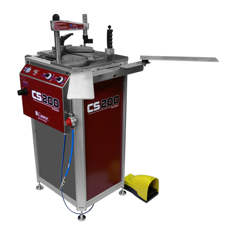
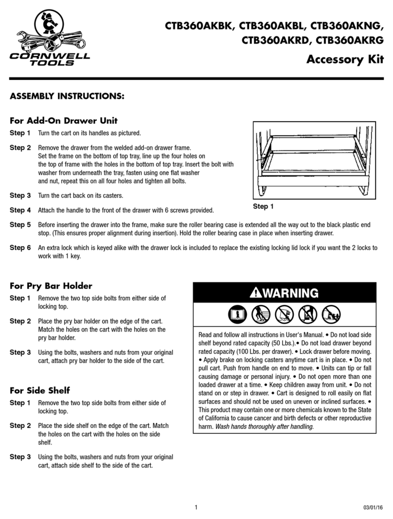
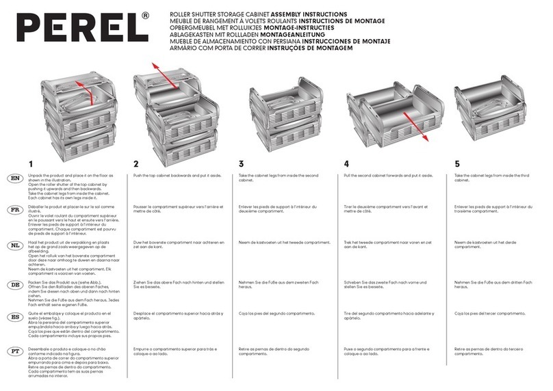
Mott Dino Operation instructions

Vorhersehbares Fehlverhalten und Zweckentfremdung ist auszuschließen.
MONTAGEANLEITUNG FÜR MOBILE BÜHNENELEMENTE
Dino
Technische Änderungen vorbehalten. Stand 06/06
INSTRUCTIONS DE MONTAGE POUR LES ÉLÉMENTS DE PODIUMS MOBILES
Dino
Grâce à un système de sécurité, un montage non conforme n'est pas possible
ASSEMBLE INSTRUCTIONS FOR MOBILE STAGE ELEMENTS
Dino
Due to a fail safe assembly system a mis-assembly is not possible.
Sous réserve de modifications techniques date 06/06
Technical modifications reserved date 06/06

Bedienung des Bühnenelementes Dino
Das Bühnenelement auf die Bodenfläche legen oder auf die Seite
stellen. Die Steckfüße in die Öffnung der Eckwinkel einschieben
und mit der Stiftschraube befestigen (Bild Nr. 1). Bei unebenen
Böden sind die Steckfüße nivellierbar (Bild Nr.2b – c + Nr.3).
Die Steckfüße mit flacher Kappe können zusätzlich mit einer
Multiplex-Platte 25 x 25 cm unterpollert werden (Bild Nr. 4).
Aufstellen der einzelnen Bühnenlemente zu einer Bühnenanlage
(s. nächste Seite).
Verstellen der Teleskop-Steckfüße mit Raster
Handrad und Sicherungsbügel lösen. Sicherungsbügel bei gewünschter
Höhe durchstecken und Handrad festziehen (Bild Nr. 2c + 3).
Utilisation du podium Dino
Poser Le podium à l’envers ou sur le côté. Introduire les pieds
enfichables dans les angles et serrer les goujons. (Fig. 1). Les pieds
sont équipés de vérins d’ajustage qui permettent de niveler en cas
d’inégalité du sol (Fig. 2b – c + Fig. 3). Les pieds enfichables avec
embout plats peuvent être soutenus par une plaquette en multiplis
25 x 25 cm (fig. 4).
Réglage des pieds télescopiques à crans
Desserrer la roue à main et débloquer la goupille. Faire glisser la
goupille à la hauteur désirée et resserrer la roue à main
(Fig. 2c + 3).
Using the Dino stage element
Lay the stage element on the floor surface or set on its side. Slide
the attachment feet into the openings in the corner brackets and
secure with the locking screws (Fig. 1). In the event of uneven floor
surfaces, the attachment feet can be levelled (Fig. 2b - c + Fig. 3).
A 25 x 25 cm multiplex plate can fitted underneath the attachment
feet with flat caps (Fig.4).
For details on how to set up the individual stage elements into a
stage system, see next page.
Adjusting the telescopic attachment feet with screen
Release the handwheel and the securing bracket. Engage the
securing bracket at the desired height and tighten down the
handwheel (Fig. 2c + 3).
Réalisation à partir des podiums individuels (voir page suivante).
1Bühnenelement Dino
2Steckfüße
3Teleskop-Steckfüße mit Raster 4Steckfüße mit flacher Kappe
Podium Dino
Pieds enfichables à embouts plats
Pieds enfichables
Pieds télescopiques à crans
Dino stage element
Attachment feet
Telescopic attachment feet Attachment feet with flat cap
with screen
2

Aufbau Bühnenfläche
Beim Aufbau einer Bühnenfläche werden für die inneren Elemente
die Schnellverbinder lang (Bild Nr. 6) und für die äußeren Elemente
die Schnellverbinder kurz (Bild Nr. 7) verwendet.
Zusätzlich werden die Elemente außen mit Verbindungsklammern
gesichert (Bild Nr. 10) (siehe Aufstellungsbeispiel Bild Nr.5).
Montage der Schnellverbinder
Die Schnellverbinder werden in die Montagenut des Alurahmens
eingeschoben und mit einem Steckschlüssel angezogen
(Bild Nr. 8).
Demontage der Schnellverbinder
Schraube des Schnellverbinders mit dem Steckschlüssel lösen.
Hakenschlüssel unter den Schnellverbinder in die Montagenut
einschieben, um 90°drehen und den Schnellverbinder herausziehen
(Bild Nr. 9).
6Schnellverbinder, lang für Innen 7Schnellverbinder, kurz für Außen
8Montage Schnellverbinder, lang 9Demontage Schnellverbinder
10 Verbindungsklammer
11 Bühnenaufbau mit Verbindungsklammern, Höhe 200 cm
5Aufstellungsbeispiel bis Höhe 200 cm (Draufsicht)
Réalisation de la surface
Pour l’assemblage des podiums, on utilise les raccords rapides
longs pour la jonction intérieure (Fig. 6) et les raccords rapides
courts pour la jonction sur l’extérieur (Fig. 7). Pour davantage de
sécurité, les éléments à l’extérieur sont reliés par une bride de
jonction. (Fig. 10) (voir exemple de configuration fig. 5).
Montage des raccords rapides
Les raccords sont introduits dans la rainure du cadre du podium
en aluminium, puis serrés à l’aide avec une clé à pipe. (Fig. 8)
Démontage des raccords rapides
Desserrer la vis du raccord à l’aide avec une clé à pipe. Introduire
la clé à ergot sous le raccord dans la rainure, effectuer un quart
de tour et retirer (Fig. 9).
Exemple d’assemblage à hauteur 200 cm (vue du dessus)
Démontage raccord rapide
Assemblage des podiums avec brides d’assemblage, hauteur 200 cm
Raccord rapide long pour l’intérieur
Bride d’assemblage
Raccord rapide court pour l’extérieur
Raccord rapide long pour l'intérieur
Setup example up to height of 200 cm (top view)
Long quick connector, inner Short quick connector, outer
Installing long quick connector Removing quick connector
Connecting retainer
Stage setup with connecting retainers, height 200 cm
Setting up stage surface
When erecting a stage surface, use the long quick connectors
(Fig. 6) for the inner elements and the short quick connectors
(Fig. 7) for the outer elements.
In addition, secure the outer elements with connecting retainers
(Fig. 10) (see setup example, Fig. 5).
Installing quick connectors
Slide the quick connectors into the installation groove of the
aluminium frame and tighten with a socket key (Fig. 8).
Removing quick connectors
Release the screw on the quick connector with the socket key.
Slide the hook key under the quick connector into the installation
groove, turn through 90
°
and pull out the quick connector
(Fig. 9).
Ab 160 cm Höhe Stahlrohr
From a height of 160 cm
Steel tube
À partir d’une hauteur de 160 cm
Tube en acier
3

Assemblage en tribune
Pour les réalisations en gradins (tribune), des brides de raccordement
sont nécessaires à l’intérieur (Fig. 13) comme à l’extérieur (Fig.14).
Les rangées de podiums sont reliées entre elles par des jonctions
courtes (Fig. 16). De plus des brides de fixation sont nécessaires
sur toute la périphérie (Fig. 15).
(Voir exemples de configuration fig. 12 + 17).
À partir d’une hauteur de 160 – 200 cm il est nécessaire
de monter des pieds enfichables en tube d’acier (Voir exemples de
configuration fig. 12 + 17).
Setting up the stand
For mobile height-adjusted stages (stands), fit the inner (Fig. 13)
and outer foot retainers (Fig. 14). Connect the individual stage
rows to each other with short quick connectors (Fig. 16). Also fit
outer connecting retainers all round (Fig. 15) (see setup example,
Figs. 12 + 17).
From a height of 160 - 200 cm fit steel-tube attachment feet
(see setup example, Figs. 12 + 17).
Exemple de réalisation à hauteur 20 – 200 cm (vue du dessus)
Bride d’assemblage
Bride pour pied enfichable extérieur
16 Jonction courte
Assemblage des podiums
Jonction courte
Aufbau Tribüne
Für mobile höhenversetzte Bühnen (Tribünen) sind die Steckfuß-
klammern innen (Bild Nr. 13) und außen (Bild Nr. 14) zu montieren.
Die einzelnen Bühnenreihen werden mit Schnellverbinder kurz
(Bild Nr. 16) untereinander verbunden. Außerdem müssen Ver-
bindungsklammern außen herum (Bild Nr. 15) montiert werden
(siehe Aufstellungsbeispiel Bild Nr. 12 + 17).
12 Aufstellungsbeispiel Höhe 20 - 200 cm (Draufsicht)
17 Bühnenaufbau
13 Steckfußklammer innen 14 Steckfußklammer außen
21
14
+ Höhe 200 cm
+ Höhe 60 cm
+ Höhe 40 cm
15
15
15
15 15
15
15
+ Höhe 20 cm
14
14
15
15
14
14
14
13
13
13
13
13
13
16
13
13
13
16
16
16
16
16
16
16
15 15
15
16
16
16
16
16 Schnellverbinder, kurz15 Verbindungsklammer
Ab einer Höhe 160 - 200 cm müssen die Steckfüße aus Stahlrohr
montiert werden ( s. Aufstellungsbeispiel Bild Nr. 12 + 17).
Brides de fixationBride pour pied
Setup example, height 20 - 200 cm (top view)
Stage setup
Inner foot retainerBride pour pied Outer foot retainer
Short quick connectorLinking Clamp
200
160
180
Ab 160 cm Höhe Stahlrohr
From a height of 160 cm
Steel tube
4
À partir d’une hauteur de 160 cm
Tube en acier

19 Geländermontage, Montage Gewindeschlitten
20 Geländermontage, Geländer mit Hutmuttern sichern
21 Geländermontage, Umgreifer festschrauben
22 Geländer-Blendenmontage
23 Blendenmontage
Accessoires
Montage des garde-corps et panneaux en bois
I
ntroduire le coulisseau (M 10 x 20) dans la rainure du cadre en
aluminium (Fig. 19). Introduire ensuite le garde-corps sur les boulons
filetés et serrer avec les écrous borgnes. (Fig. 20). Serrer l’élément
de prise sur le profilé en alu (Fig. 21)
Important : la pose de garde-corps est obligatoire à
partir d’une hauteur de podium de 50 cm.
Montage des panneaux en bois sur les garde-corps
Poser les panneaux sur l’ossature et fixer à l’aide des boulons à
tête noyée. (Fig. 22)
Montage des panneaux en bois
Introduire le coulisseau (M 6 x 12) dans la rainure de montage du
cadre en aluminium. Poser ensuite les panneaux et fixer à l’aide
d’un écrou douille et d’une clé hexagonale. (Fig. 24).
Accessories
Installing siderail and panels
Slide the threaded slide (M 10 x 20) into the installation groove of the
aluminium frame (Fig. 19). Then fit the siderail on the threaded bolts
and secure with cap nuts (Fig. 20). Firmly screw the encompassing
piece to the bottom of the aluminium section (Fig. 21).
Important: Siderails must be installed starting from stage
heights of approx. 50 cm.
I
nstalling siderail panel
Position the panel against the siderail upright and secure with hexagon
screw (Fig. 22).
Installing panels
Slide the threaded slide (M 6 x 12) into the installation groove of the
aluminium frame. Then insert panels and tighten down the sleeve nuts
with the Allen key (Fig. 24).
Montage garde-corps, montage coulisseau
Montage garde-corps, serrer les boulons
Montage garde-corps, serrer l'élément de prise
Montage du bardarge en bois sur les garde-corps
Montage du bardarge
Installing siderail, installing threaded slide
Installing siderail, secure with cap nuts
Installing siderail, screw the encompassing piece
Installing siderail panel
Installing panels
Zubehör
Geländermontage und Geländer mit Blendenmontage
Gewindeschlitten (M 10 x 20) in die Montagenut des Alurahmens
einschieben (Bild Nr. 19). Danach Geländer auf Gewindebolzen
aufstecken und mit Hutmuttern sichern (Bild Nr. 20). Den Umgreifer
am Aluminiumprofil unten festschrauben (Bild Nr. 21).
Wichtig: Ab ca. 50 cm Bühnenhöhe müssen Geländer
angebracht werden.
Geländer-Blendenmontage
Blende an den Geländerholm ansetzen und mit Senkschraube
befestigen (Bild Nr. 22).
Blendenmontage
Gewindeschlitten (M 6 x 12) in die Montagenut des Alurahmens
einschieben. Danach Blenden einsetzen und Hülsenmutter mit
Innensechskantschlüssel festschrauben (Bild Nr. 24).
5

24
25
26
27
28 29
Treppen- und Treppengeländermontage
Treppenstufen aneinanderstellen und mit Sechskantschrauben
(M 8 x 70) und Flügelmuttern befestigen. Aufsteckrohre ebenfalls
mit Sechskantschrauben (M 8 x 90) und Flügelmuttern an der
oberen Treppenstufe festschrauben. Gewindeschlitten (M 6x16)
in die Montagenut des Alurahmens einschieben und mit den
Befestigungswinkeln und Handrädern (M 6) verbinden (Bild Nr.
24 + 25).
Treppenmontage mit Geländer
Wie oben handhaben; Aufgangstreppe mit Treppengeländer
montieren (Bild Nr. 26 ).
Vorhangmontage
Pilzkopfband in die Aussparung des Bühnenprofils kleben und den
Vorhang mit dem angenähten Veloursband andrücken
(Bild Nr. 28 + 29).
Treppenmontage mit seitlicher Blende, und Blende vorn
Treppenstufen aneinanderstellen und mit Sechskantschrauben
(M 8 x 70) und Flügelmuttern befestigen. Gewindeschlitten
(M 6 x 12) in die Montagenut des Alurahmens einschieben. Danach
Aufgangstreppe an die Bühne stellen und mit Hülsenmutter und
Innensechskantschlüssel festschrauben (Bild Nr. 27).
24 Treppenmontage
26 Treppenmontage
mit Geländer
27 Treppenmontage
mit Blenden
28 Pilzkopfband
29 Vorhangmontage mit
Pilzkopfband
Montage de l’escalier et de la main-courante
P
oser les marches par ordre de grandeur et fixer à l’aide des
boulons à tête hexagonale (M 8 x 70) et des écrous papillons. De
même, fixer les tubes enfichables sur la marche supérieure en
utilisant les boulons à tête hexagonale (M 8 x 90) et les écrous
papillon. Introduire le coulisseau dans la rainure du cadre aluminium
et fixer à l’aide des équerres de fixations et des vis à main (M 6).
(Fig. 24 + 25).
Pour la pose de la main courante, procéder de la même manière
que pour les tubes enfichables et fixer à l’aide des boulons à tête
hexagonale (M 8 x 90) et des écrous papillons sur le support des
marches. (Fig. 26).
Montage de l’escalier avec main courante
Procéder comme ci-dessus. Assembler l’escalier et la main courante
(Fig. 26 ).
Montage de la jupe
Coller la bande avec les crochets minuscules dans la rainure du
profil du podium et fixer la jupe en pressant la bande munie de
boucles sur celles munie de crochets. (Fig. 28 + 29).
Montage de l’escalier avec contremarches, et bardage latérale
Poser les marches par ordre de grandeur et fixer à l’aide des
boulons à tête hexagonale (M 8 x 70) et des écrous papillons.
Introduire le coulisseau dans la rainure du cadre aluminium. Poser
l’escalier contre le podium et serrer les écrous à douille à l’aide
d’une clé hexagonale. (Fig. 27).
Fitting skirting
Stick mushroom-head tape into the recess in the stage section and
press on the skirting with the stitched-on velours tape
(Figs. 28 + 29).
Assembling steps and siderail
Position the individual steps against each other and secure with
hexagon screws (M 8 x 70) and wing nuts. Likewise secure the
attachment tubes to the top step with hexagon screws (M 8 x 90)
and wing nuts. Slide the threaded slides (M 6 x 16) into the
installation groove of the aluminium frame and connect with the
retaining brackets and handwheels (M 6) (Figs. 24 + 25).
Proceed as above; instead of the attachment tubes, install the
siderail to the access steps with hexagon screws (M 8 x 90) and
wing nuts (Fig. 26).
Assembling steps with side panel, and front panel
Position the individual steps against each other and secure with
hexagon screws (M 8 x 70) and wing nuts. Slide the threaded
slides (M 6 x 12) into the installation groove of the aluminium
frame. Then position the access steps against the stage and tighten
down with sleeve nut and Allen key (Fig. 27).
Wie oben handhaben; anstelle der Aufsteckrohre wird das
Treppengeländer mit Sechskantschrauben (M 8 x 90) und
Flügelmuttern an die Aufgangstreppe montiert (Bild Nr. 26).
Assembling steps with siderail
Proceed as above; install the access steps with the siderail
(Figs. 26 ).
Montage de l’escalier
avec main courante
Montage de l’escalier
avec bardage
Montage de la jupe
avec bande Velcro
Montage de l’escalier
Bande Velcro
Assembling steps
Assembling steps with
siderail
Assembling steps with
panels
Fitting skirting with
mushroom-head tape
Mushroom-head tape
6