Mountfield SWING 3.2 kW Mounting instructions

HEAT PUMP for pool water heating
WÄRMEPUMPE zur Schwimmbeckenwassererwärmung
POMPA CIEPŁA do podgrzewania wody basenowej
ТЕПЛОВОЙ НАСОС для нагрева воды в бассейнах
SWING 3.2 kW
EN Maintenance and User's Manual
DE Bedienungs- und Wartungsanleitung
PL Instrukcja obsługi i konserwacji
RU Руководство по эксплуатации и техническому обслуживанию
3BTE0538/3EXB0572
CZ-10/2020 –No.: 815-A
Mountfield Export Team
www.mountfield-export.com
Mountfield, a.s., Všechromy 56/Highway D1, Exit 15, 251 63 Strančice, Czech republic

1
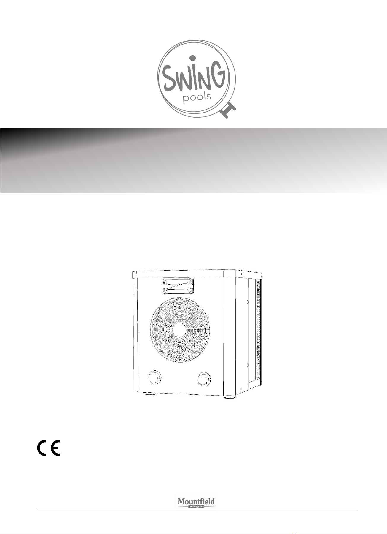
HEAT PUMP
for pool water heating
SWING 3.2 kW
Maintenance and User's Manual
3BTE0538/3EXB0572
CZ-10/2020 –No.: 815-A

2
Contents
1. Introduction
2. Safety instructions
3. Specifications
4. Installation
5. Commissioning
6. Operation and controls
7. Maintenance
1. Introduction
Thank you for choosing our heat pump. It is designed to heat water in your pool at the ambient temperature from 12°C to 40°C.
This user’s manual contains all necessary information for installation, operation and maintenance of the equipment. Read the user’s
manual thoroughly before starting any handling or maintenance. The manufacturer takes no responsibility for any injury or damage
of property in case of incorrect installation, commissioning and insufficient maintenance.
This document is an integral part of the product and must be kept in the machine rook or close to the heat pump.
The heat pump is designed for pool water heating and for economical maintenance of its temperature at the required level. Any
other use is considered unintended.
The heat pump has the best efficiency at air temperatures of 15-30°C. At temperatures below 12°C the equipment has low
efficiency, and above +35°C the equipment may overheat. We do not recommend use of the equipment in ambient temperatures
outside the range of 12-35°C.
The length of the pipeline between the heat pump and the pool should not exceed 10 m and should be fitted with suitable heat
insulation to maintain the temperature. Longer and/or thermally uninsulated pipeline has negative influence on the heating
efficiency.
ATTENTION:
➢Observe the recommendations in this manual during operation and maintenance.
➢Only use original spare parts during repairs.
ATTENTION: This manual contains all necessary information for the installation of the heat
pump.
This manual must be read and the instructions for installation and subsequent maintenance
must be adhered to. Incorrect installation results in the expiry of the guarantee.
The manufacturer is not responsible for damages caused by persons, objects and error due to failure to adhere to the
instructions given herein. Any use in violation with the manufacturer’s recommendations will be considered incorrect
use.
Note: The illustrations and descriptions in this manual are not binding and may differ from the actual supplied product. The
manufacturer and the supplier reserve the right to make changes without the obligation to update this manual.
Waste sorting symbol in countries of the European Union
Protect the environment! This power equipment may not be disposed of together with
household/communal waste. Old electrical equipment must be returned to a collection yard for
environmentally friendly waste disposal. Use the collective waste handling system to return the old
equipment. They will accept the product from you and ensure safe disposal.
Contact your administrative bodies of the town or municipality, which will provide further information
regarding product disposal.

3
2. Safety instructions
ATTENTION: DANGER. Contains flammable gas.
Only qualified professionals may perform any service of this equipment!
ATTENTION: The equipment contains live electrical parts. Only a qualified electrician may
open the equipment. Electric shock hazard.
(a) The equipment is not designed for use by persons (including children) with reduced physical, sensory or mental
capacities, unless supervision and training by a qualified person is provided; persons not familiar with the operation
in the scope of this manual; persons under the influence of drugs, intoxicating substances, etc., reducing the
capability of quick reaction.
(b) The placement of the heat pump must comply with ČSN 33 2000-7-702, i.e., a min. 2 m from the outer pool edge.
(c) The power-supply circuit of the heat pump must comply with the relevant standard (ČSN 33 2000) and must be fitted
with a residual current device with breaking current of 30 mA.
(d) Only a person with relevant electrical-engineering qualification may perform any interventions on the wiring of the
heat pump and its power-supply circuit.
(e) Do not install the heat pump in places in which it may be flooded with water.
(f) Prevent children from playing in the operational area of the heat pump. The main switch of the heat pump must be
located outside the reach of children.
(g) Do not leave the heat pump running if covers are in place, and don’t insert any objects into the apertures in the
covers. The rotating fan may cause serious injury. The internal pipeline is hot during operation and may cause burns
when touched.
(h) If you notice any unusual noise, odour or smoke from the heat pump, immediately switch the power supply off and
ensure professional inspection of the entire equipment.
(i) Should you notice any damage on the power-supply cable or on the extension cable, immediately switch the heat
pump power-supply fuse off and repair the defect.
(j) Only persons with relevant qualifications may perform repairs of the heat pump and interventions in the pressure
coolant circuit.
(k) The maintenance and operation must comply with this user’s manual.
(l) Only use original spare parts. Do not remove or modify any parts of the heat pump. In case on non-compliance with
the recommendations herein, the guarantee cannot be claimed.

4
3. Specifications
MODEL
SWING 3.2 kW
TYPE
BP-32WS-MY
XP045miniR3
XP060miniR3
Specifications at +26°C ambient, +26°C water
Heating capacity
(kW)
3.2
4.2
5.5
Operational absorbed power
(kW)
0.5
1.00
1.31
COP (operational)
6
4.2
4.2
Specifications at +15°C ambient, +26°C water
Heating capacity
(kW)
2.2
3.2
4.2
Operational absorbed power
(kW)
0.45
0.91
1.2
COP (operational)
4.6
3.5
3.5
Electrical specifications
Power supply
(V~/ Hz)
230 / 50
230 / 50
230 / 50
Rated current
(A)
2.5
4.4
5.8
Recommended protection
(A)
10
13
16
Protection level
IP X4
IP X4
IP X4
Protection class
I
I
I
Pool installation specifications
Recommended pool capacity
(m3)
<11
<15
<20
Max. pool capacity
(m3)
18
30
60
Recommended water flow
(m3/h)
1.5-4
2
2.5-3.2
Optimal water flow
(m3/h)
3
Installation dimension
mm
32/38
32/38
32/38
General specifications
Exchanger
titanium in PVC
titanium in PVC
titanium in PVC
Compressor
rotating
rotating
rotating
Air flow direction
horizontal
horizontal
horizontal
Noise level (10 m)
(dB(A))
36
46
46
Noise level (1 m)
(dB(A))
46
55
55
Coolant (heat carrier)
R32
R32
R32
Coolant filling weight
(g)
270
290
450
CO2 quota
t
0.18
0.2
0.31
Weight net / gross
(kg)
20 / 22
26 / 30
28 / 32
Overall dimensions (D x H x V)
(mm)
360 x 355 x 410
434 x 433 x 460
434 x 433 x 460
Note: The values of the thermal power and operational absorbed power may differ according to the climatic and operational
conditions.

5
Pool water specifications
The heat pump is designed for pool water heating, which meets the health and safety requirements of water for bathing. Limit
values for heat pump operation: pH value in range 6.8-7.9, total chlorine content may not exceed 3 mg/l. Water hardness must be
maintained at the lower level of the optimal range, i.e., just above 8°N.
Heat pump dimensions
(mm)
A
360
B
355
C
410
D
170
E
95
F
20
G
65
Note: The dimensions are given in millimetres.
ATTENTION: The manufacturer reserves the right to modify the product, which will not affect its basic properties.
4. Installation
Handling the heat pump
During transport use the original packaging, or package the equipment prior to transport in a similar manner.
Do not lift the heat pump by the exchanger coupling. It may damage the equipment.
Installation of heat pump into filtration circuit
(1) This thermal pump must be installed in compliance with the instructions herein. Otherwise there is a risk of damage to the
equipment, injury of persons, animals or even death.
(2) The equipment is designed for outdoor use with good ventilation. To ensure optimal efficiency, the placement must meet the
following conditions:
1. Good air ventilation
2. Stable power supply
3. Pipeline with pool filtration
(3) Avoid installation in places with increased dustiness, which leads to gradual deterioration of the heat exchanger, or in places
where the stream of cold air or noise may be disturbing (windows, terrace, arbour).
(4) Do not orient the air output against the direction of prevailing winds.
(5) Avoid installation of the equipment in places with limited air circulation, or where obstacles to air flow are present. Obstacles
limit continuous supply of fresh air; suction of cool air back into the heat pump significantly degrades its efficiency.
(6) During operation, water condenses on the blades of the evaporator and the resulting condensate flows to the bottom part of
the heat pump and then out of its base. If the outflow of water is disturbing, collect it into a suitable vessel, or arrange the flow
into the sewage.
(7) Consult indoor installation of the heat pump with a specialist.
(8) In case of bypass installation, ensure a flow of no more than 30%.

6
(9) The image on the side shows the minimum distance
requirements of the heat pump from obstacles.
(10) The distance of the equipment from the edge of the pool may not be less than
2 m. Installation of the heat pump ensuring the overall length of
connecting hoses doesn’t exceed 30 m is recommended. Remember, that the
longer the connecting hoses, the greater the heat and pressure losses in the
line.
(11) Optimal heat exchange is ensured with the water flow specified on the name
plate of the pump and in the specifications.
(12) The equipment must be placed on a level and solid surface, e.g., on a concrete
plinth or steel support.
(13) During installation, it is necessary to take winter decommissioning of the heat
pump into account, which requires timely disconnection before freezing
temperatures occur, disconnection of the heat pump from the filtration circuit and, including other parts of the water circuit,
drainage of all water. The guarantee does not cover frost damage.
(14) The heat pump is fitted with connecting branches for connection of pool hoses with a diameter of 32 or 38 mm.
In case of aboveground installation, always use pipes, not hoses. The exchanger threaded coupling cannot support the
exchanger’s weight and may result in damage to the exchanger.
(15) The placement of water treatment equipment (chlorinator, ozonator, etc.) has significant impact on the service life of the heat
pump. Disinfection dosage equipment must be placed so the dosage outlet is connected downstream from the heat pump. In
this part of the line an air trap, preventing back flow of water, must at least be installed.
Note: The manufacturer only supplies the heat pump, hose pins and hose clamps. Request all other components, including hoses
and brackets, from your dealer.
Connection diagram:
1 –filtration pump
2 –filtration container
3 –chemical water treatment equipment (chlorinator,
ozonator, etc.)
Note: The water treatment equipment must be
located downstream from the thermal pump.
Hose clamp
Hose

7
Electrical connection
IMPORTANT: The heat pump is supplied with power supply cable with a fork for connection to a power
outlet with an integrated residual current device. The outlet installation must comply with the
requirements of ČSN 33 2000.
We recommend the use of a double outlet with common switching (switch or switch clock).
Note: Before connecting the equipment, check that the supply voltage matches the operational voltage of the heat pump.
IMPORTANT: This product is fitted with a residual current device (RCD) at the end of the power supply
cable. The residual current device (RCD) must be tested before each use:
1. Plug the power-supply cable fork into the power outlet.
2. Press the RESET button on the RCD. The indicator on the RCD should turn on.
3. Switch the heat pump using the ON/OFF button.
4. Press the TEST button on the RCD. The indicator on the RCD should turn off and the heat pump should switch off.
If the indicator on the RCD doesn’t turn off and the heat pump doesn’t switch off, the RCD is faulty.
5. Press the RESET button on the RCD. The indicator on the RCD should turn on.
If the in RCD indicator doesn’t turn on, the RCD is faulty.
IMPORTANT: Do not use the heat pump if the RCD doesn’t work properly. Disconnect the power-supply
cable until the cause of the fault is identified and removed. Let a qualified electrician repair the fault. Do
not repair the RCD, it contains no user-repairable parts. Opening the RCD will result in termination of the
guarantee.
Wiring diagram
Key:
Low pressure switch
Water temperature
Compressor temperature . Sensor of coolant temperature
at compressor discharge
Copper temperature ......... Coolant temperature sensor at
evaporator inlet
CM
FM
RELAY
Y/G ................................... earthing
C1, C2 ............................... capacitors
RED/BLACK/WHITE WIRE

8
5. Commissioning
Commissioning
IMPORTANT: Always handle the heat pump with the cover oriented up. If you are not sure this instruction
was observed, leave the heat pump standing in place for 24 hours before switching it on.
Switch the filtration pump on and check, that a sufficient amount of water flows through the heat pump and that no water leaks
out.
Connect the heat pump to the power supply, test the RCD and switch it on using the ON/OFF switch on the electronic control panel.
The heat pump will start with a certain delay (see below).
After several minutes make sure the air flowing out of the heat pump is significantly cooler than the air sucked in.
Based on the initial temperature of the pool water and the air temperature, it may take several days to heat the water to the
required temperature. Covering the pool with a cover or solar tarpaulin may significantly reduce this time.
Automatic control systems
Heat pump operation control based on water temperature
The temperature in the exchanger inlet is compared by the control system with the target temperature and, based on the result, the
heat pump is switched on and off. The thermostat sensitivity is factory set to 1°C, switching off takes place when the water
temperature in the exchanger reaches the target temperature; switching on takes place when the water temperature in the
exchanger drops below the thermostat sensitivity value of the target temperature.
Note: When the temperature for switching the heat pump on is reached, a delay is activated. The heat pump will switch on when it
elapses.
Delay
The equipment is fitted with a time-delay device with a pre-set delay to protect the control elements in the circuit and to prevent
repeated restarts and contactor flutter. This delay will automatically restart the equipment approx. 2 minutes after each shut down
of the heat pump. The delay will even be activated after a short power outage to prevent starting before the pressure inside the
heat pump is equalised. Power outage during the delay doesn’t affect the time interval.
Safety temperature and pressure systems
The equipment is equipped with temperature sensors and a pressure sensor, which automatically switch the equipment off when
the temperature and pressure values are exceeded.
In case of a fault on any of the systems (system fault, disconnection or abnormal value measured), the display will show an error
message, see Chapter 6. Maintenance, Error messages, below.

9
6. Operation and controls
Operational instructions
IMPORTANT:
❑Pool heating by the heat pump requires the operation of the filtration pump and water flow through the heat
exchanger.
❑Never switch the heat pump on if it contains no water and if the filtration equipment is not working.
❑Do not cover the heat pump; ambient air must flow during operation.
❑Protect the heat pump from freezing. Discharge water from the filtration and heat pump and ensure winter
preparation according to the manual before the first frost.
Water condensation
Lower evaporator temperatures during heat pump operation causes air humidity condensation on the evaporator blades and
formation of condensate or icing. If the relative air humidity is very high, several litres of water may condensate in one hour. The
water flows from the blades to the bottom of the cabinet and then out through its base.
It is very easy to mistake condensed water for water leakage from inside the heat pump. There are two simple methods to check
whether it is condensation or not:
1. Switch the equipment off and only leave the pool pump running. If the water stops flowing, it is condensed water.
2. Perform a test for chlorine presence in the flowing water (if chlorine is used for pool disinfection) –if the flowing water
doesn’t contain chlorine, it is condensation.
Note: Eventual ambient humidity is caused by the condensation of water vapours and is not a problem.
Possible issues caused by external conditions
Under certain external conditions the exchange of heat between the coolant and water on one side, and between the coolant and
air on the other, may be insufficient. This can lead to increased pressure in the coolant circuit and increased compressor power
consumption.
The heat pump is fitted with pressure and temperature sensors, which will prevent incorrect operation under extreme conditions.
The cause may be insufficient water flow. To increase the heat exchange coolant water, close the by-pass valve (if installed) to
increase the flow of water through the exchanger.
Notes on heat pump operation
❑The efficiency of the heat pump increases with the rising temperature of ambient air.
❑Several days may be required to reach the required temperature. This time is normal and particularly depends on the
climatic conditions, volume of pool water, water surface area, heat pump operation time and thermal loss from the pool
(e.g. surface evaporation, heat permeation, radiation, etc.). In case no adequate measures are taken to reduce heat loss,
high water temperature maintenance is not economical, and in some cases not possible.
❑To reduce heat loss when the pool is not in use, apply a cover or solar tarpaulin.
❑The water temperature in the pool should not exceed 30°C. Warm water is not very refreshing and also creates optimal
conditions for algae growth. Certain pool components may also have temperature limitations. For example, foil pool foils
may become softer. Therefore do not set the thermostat to more than 30°C.

10
Operating
Connect the heat pump into a power outlet and test the RCD (see above). The display should then read OFF.
Switching the heat pump on/off
Press the button to switch the heat pump on. The display shows the inlet water temperature.
Press the button again to switch the heat pump off.
Set the target water temperature
Use the and buttons to set the water temperature (range: 15-35°C).
The temperature value on the display is flashing during setting. The pre-set temperature is saved after brief inactivity, the
temperature value will stop flashing and the display will switch to show the water temperature on the exchanger inlet.
ATTENTION: The heat pump can only operate if a sufficient amount of water flows through it from the filtration system.
Parameter control and set-up
Press and hold the button for approx. 5 s to enter the parameter control and settings mode.
Press the or button to select the parameter code, press the button again to display the
flashing value of the parameter. Use the and buttons to change the value and save it by
pressing the button. If you don’t press the button while the value is flashing, the changes
will not be saved.
Code
Parameter
Range
Default
Adjustable
A
Water temperature on the exchanger inlet
-19...99°C
-
No
B
Coolant temperature at evaporator inlet
-19...99°C
-
No
C
Air temperature at the compressor discharge
-19...99°C
-
No
1
Water target temperature
15...35°C
27°C
Yes
2
Thermostat sensitivity setting
i.e. the difference between the switch OFF/ON
temperature
1...10°C
1°C
Yes
3
Compressor outlet temperature protection
30...80°C
47°C
Yes
4
Auto resume after power failure
0/1
1
Yes
5
Freezing check interval
10-90 min
40 min
Yes
6
Switch-on temperature for de-frosting
-30...0°C
0°C
Yes
7
Switch-OFF temperature for de-frosting
1...30°C
2°C
Yes
8
Defrosting time
10-40 min
30 min
Yes

11
7. Maintenance
Maintenance
ATTENTION: The equipment contains live electrical parts. Only a qualified electrician may open the
equipment. Electric shock hazard.
IMPORTANT: Prior to any intervention on the equipment ensure that it is disconnected from power
supply.
ATTENTION: DANGER. Contains flammable gas.
Only qualified professionals may perform any service of this equipment!
(a) Regularly check the water line for water leaks or air suction that will cause aeration of the system.
(b) Clean the pool and filtration regularly to prevent any damage of the equipment due to a polluted or clogged filter.
(c) Regularly check the power supply and the condition of the supply cable. If the equipment starts to behave abnormally,
immediately switch off the equipment and contact an authorised service technician.
(d) Regularly check the technical condition of the heat pump and remove any dirt from the evaporator to prevent any reduction of
heat exchange efficiency.
(e) Regularly check the working area of the pump, keep it clean and remove any accumulated dirt, leaves or snow.
(f) If you are not using the heat pump, disconnect it from the grid, discharge the water and cover it with a water resistant tarpaulin
or PE sheet.
(g) Wash the heat pump from the outside using normal detergent and clean water.
(h) Regularly clean the external surface of the evaporator from accumulated dirt using a soft brush. Check the evaporator surface for
any blade damage. The blades can be straightened using a flat, blunt tool. The guarantee does not cover mechanical damage to
the blades.
(i) Regularly check the tightening of the bolts, and the wear of the power-supply cable. Clean corroded parts with a wire brush and
treat them with anti-corrosion coating.
(j) Regularly remove the top cover and clean the inside of the heat pump from dirt.
(k) Only a qualified expert can repair internal parts of the heat pump.
Winter preparation
(a) Disconnect the pump from the grid.
(b) Discharge water from the pump by disconnecting the pool hoses from both couplings of the filtration circuit.
(c) Remove remaining water from the exchanger by tilting it or by evacuation. Make sure there is no water in the exchanger
(DANGER OF FREEZING).
(d) Store the equipment in a dry place during winter. Prevent water from entering the exchanger.
IMPORTANT: Correct winter preparation is very important. The pump exchanger must be free of water.
The guarantee does not cover eventual frost damage of the exchanger.

12
Error messages
Error
Component
Possible cause
Removal
P1
Water temperature
sensor
Interrupted cable to the sensor,
power-supply or faulty sensor.
Check the sensor, wires and connection. If
faulty, replace.
If the error persists, replace the control
unit.
P2
Temperature sensor
at compressor
discharge
Interrupted cable to the sensor,
power-supply or faulty sensor.
Check the sensor, wires and connection. If
faulty, replace.
If the error persists, replace the control
unit.
P3
Temperature sensor
at evaporator inlet
Interrupted cable to the sensor,
power-supply or faulty sensor.
Check the sensor, wires and connection. If
faulty, replace.
If the error persists, replace the control
unit.
P4
Auto power down
The water flow through the
exchanger is low or not present
Check the filtration system for water flow
obstructions.
2)
P5
Minimal pressure
switch
Insufficient coolant in the
system.
1)
Coolant leak from system.
1)
1) Call a cooling engineer to check your cooling system.
2) Should the P4 error persist, the system will attempt to restart after 3 minutes; it restarts if the temperature at the compressor
discharge drops below temperature set by parameter 3. If the P4 error emerges 3 times in a row, the system will shut down and the
cause must be removed and the heat pump power-supply disconnected and reconnected manually.
IMPORTANT: Should an intervention in the wiring be needed, contact an authorised service technician.
Solution of other possible issues
Error
Demonstration
Possible cause
Solution
Heat pump
doesn’t
work
Display shows
nothing
Equipment has no power supply
Check the cable, supply, protection,
etc.
Display shows the
water temperature
1. Water temperature reached pre-
set value, heat pump is in pre-set
temperature maintenance mode
2. Equipment is preparing for start-
up (delay 3 min)
1. Check the pre-set temperature
2. Wait a min 3 minutes
Short time
of operation
The display shows
water temperature
and no error
message
1. Fan is not turning
2. Insufficient air flow
3. Coolant leakage
1. Have the internal fan wiring
checked
2. Check possible obstructions of the
air flow, eventually relocate the
heat sensor.
3. Let a professional check the
coolant quantity.
Water
sediment
Water sediment
present on the heat
pump
1. Sediment from the surrounding
environment
2. Water leakage
1. Clean the sediment.
2. Check for water leaks from the
exchanger
Icing on
evaporator
Icing on evaporator
Coolant leakage
Have a professional check the
coolant volume
If problems persist, contact your dealer.
Warranty conditions, service and spare parts
Guarantee conditions apply as described in the guarantee certificate. Service and spare parts are provided by Mountfield a.s.
through the outlets and service centres.
1
WÄRMEPUMPE
zur Schwimmbeckenwassererwärmung
SWING 3,2 kW
Bedienungs- und Wartungsanleitung
3BTE0538/3EXB0572
CZ-10/2020 - Nr.: 815-A

2
Inhaltsverzeichnis
1. Einleitung
2. Sicherheitshinweise
3. Spezifikation
4. Installation
5. Inbetriebnahme
6. Betrieb und Bedienung
7. Wartung
1. Einleitung
Vielen Dank, dass Sie sich für unsere Wärmepumpe entschieden haben. Sie soll das Wasser in Ihrem Pool erwärmen, und zwar bei
einer Umgebungstemperatur von 12 °C bis 40 °C.
Diese Bedienungsanleitung enthält alle Informationen, die für die Installation, den Betrieb und die Wartung des Geräts erforderlich
sind. Bitte lesen Sie die Bedienungsanleitung sorgfältig durch, bevor Sie Wartungsarbeiten durchführen oder mit dem Gerät
hantieren. Der Hersteller dieses Geräts übernimmt keine Haftung für Verletzungen oder Sachschäden bei unsachgemäßer
Installation, Inbetriebnahme oder unzureichender Wartung.
Dieses Dokument ist untrennbarer Bestandteil des Produkts und muss im Maschinenraum oder in der Nähe der Wärmepumpe
aufbewahrt werden.
Die Wärmepumpe dient ausschließlich zur Erwärmung von Poolwasser und zum wirtschaftlichen Halten der Temperatur auf dem
gewünschten Wert. Jede andere Verwendung gilt als nicht bestimmungsgemäß.
Die Wärmepumpe erreicht bei Lufttemperaturen von 15 ÷ 30 °C den höchsten Wirkungsgrad. Bei Temperaturen unter 12 °C hat das
Gerät einen geringen Wirkungsgrad, und bei über + 35 °C kann es überhitzen. Wir empfehlen daher, das Gerät nicht außerhalb des
Umgebungstemperaturbereichs von 12 ÷ 35 °C zu verwenden.
Das Rohr zwischen der Wärmepumpe und dem Pool sollte nicht länger als 10 m sein und es sollte mit einer geeigneten
Wärmedämmung versehen sein, um die Wärme zu halten. Eine längere und/oder nicht wärmegedämmte Rohrleitung wirkt sich
negativ auf die Heizleistung aus.
ACHTUNG:
➢Beachten Sie während des Betriebs und der Wartung die Empfehlungen in dieser Anleitung.
➢Stellen Sie bei Reparaturen sicher, dass nur Originalersatzteile verwendet werden.
ACHTUNG: Diese Anleitung enthält alle erforderlichen Informationen zur Installation der
Wärmepumpe.
Vor der Installation muss zunächst diese Anleitung gelesen werden und die Anweisungen für die
Installation und nachfolgende Wartung sind sorgfältig zu befolgen. Falsche Installation führt zum
Ausschluss der gesamten Garantie.
Der Hersteller haftet nicht für Schäden, die durch Personen, Gegenstände und Fehler verursacht werden, die auf die
Nichtbeachtung der hier gegebenen Anweisungen zurückzuführen sind. Jede Verwendung, die nicht den Empfehlungen
des Herstellers entspricht, gilt als nicht bestimmungsgemäß.
Anmerkung: Die Abbildungen und Beschreibungen in dieser Anleitung sind unverbindlich und können von dem tatsächlich
gelieferten Produkt abweichen. Der Hersteller und der Lieferant behalten sich das Recht vor, Änderungen vorzunehmen, ohne zur
Aktualisierung dieser Anleitung verpflichtet zu sein.
Symbol für die Müllsortierung in Ländern der Europäischen Union

3
Schützen Sie die Umwelt! Dieses Elektrogerät darf nicht gemeinsam mit dem Haus-/Restmüll entsorgt
werden. Das ausgediente Elektrogerät ist im Wertstoffhof zur umweltfreundlichen Abfallentsorgung
abzugeben. Nutzen Sie für die Rückgabe des alten Elektrogeräts ein kollektives Abfallsammelsystem.
Das Produkt wird dort zum Zwecke der sicheren Entsorgung entgegengenommen.
Setzen Sie sich mit den Verwaltungsbehörden Ihrer Stadt bzw. Gemeinde in Verbindung, wo Sie weitere
Informationen bzgl. der Produktentsorgung erhalten.
2. Sicherheitshinweise
ACHTUNG: GEFAHR. Enthält brennbares Gas.
Servicearbeiten an diesem Gerät dürfen nur von qualifiziertem Personal durchgeführt
werden!
ACHTUNG: Das Gerät enthält spannungsführende elektrische Komponenten. Das Gerät darf
nur von einer Person mit entsprechender elektrotechnischer Qualifikation geöffnet werden.
Stromschlaggefahr.
(a) Das Gerät ist nicht bestimmt für die Verwendung durch Personen (einschließlich Kindern) mit verminderten
körperlichen, sensorischen oder mentalen Fähigkeiten, sofern nicht ihre Beaufsichtigung und Anleitung durch eine
verantwortliche Person gewährleistet sind, Personen, die nicht mit der Bedienung im Umfang dieser Anleitung
vertraut sind, sowie Personen unter Einfluss von Medikamenten, Betäubungsmitteln u. Ä., welche die Fähigkeit der
schnellen Reaktion vermindern.
(b) Der Standort der Wärmepumpe muss der Norm ČSN 33 2000-7-702 entsprechen, d. h. er muss mindestens 2 m vom
Außenrand des Pools entfernt sein.
(c) Der Stromversorgungskreis der Wärmepumpe muss der einschlägigen Norm (ČSN 33 2000) entsprechen und mit
einem Fehlerstrom-Schutzschalter mit einem Abschaltstrom von 30 mA ausgestattet sein.
(d) Eingriffe in die elektrische Installation der Wärmepumpe und des Stromversorgungskreislaufs dürfen nur von einer
Person vorgenommen werden, die über eine entsprechende elektrotechnische Qualifikation verfügt.
(e) Die Wärmepumpe darf nicht an Standorten installiert werden, an denen sie mit Wasser überflutet werden kann.
(f) Stellen Sie sicher, dass im Arbeitsbereich der Wärmepumpe keine Kinder spielen. Der Hauptschalter der
Wärmepumpe muss sich außerhalb der Reichweite von Kindern befinden.
(g) Eine Wärmepumpe, die nicht komplett abgedeckt ist, darf nicht in Betrieb gelassen werden; in die Öffnungen in den
Abdeckungen dürfen keine Gegenstände gelangen. Der rotierende Lüfter kann schwere Verletzungen verursachen.
Die innere Rohrleitung ist während des Betriebs heiß; bei Berührung kann es zu Verbrennungen kommen.
(h) Wenn Sie ungewöhnliche Geräusche, einen Geruch oder Rauch von der Wärmepumpe bemerken, schalten Sie die
Stromversorgung sofort aus und stellen Sie sicher, dass das Gerät ordnungsgemäß überprüft wird.
(i) Wenn Sie feststellen, dass das Anschlusskabel oder das Verlängerungskabel beschädigt ist, schalten Sie sofort den
Schutzschalter der Pumpe aus und beheben Sie den Fehler.
(j) Reparaturen an der Wärmepumpe und Eingriffe in den Kühlmitteldruckkreis dürfen nur von einer entsprechend
qualifizierten Person durchgeführt werden.
(k) Die Wartung und der Betrieb müssen gemäß dieser Anleitung ausgeführt werden.
(l) Nur Originalersatzteile verwenden. Keine Teile der Wärmepumpe entfernen oder modifizieren. Bei Nichtbeachtung
dieser Empfehlungen können auf dieses Gerät keine Garantieansprüche erhoben werden.
3. Spezifikation

4
MODELL
SWING 3,2 kW
TYP
BP-32WS-MY
XP045miniR3
XP060miniR3
Parameter bei +26 °C Umgebungstemperatur, +26 °C Wassertemperatur
Heizleistung
(kW)
3,2
4,2
5,5
Betriebsleistung
(kW)
0,5
1,00
1,31
(Betriebs-)COP
6
4,2
4,2
Parameter bei +15 °C Umgebungstemperatur, +26 °C Wassertemperatur
Heizleistung
(kW)
2,2
3,2
4,2
Betriebsleistung
(kW)
0,45
0,91
1,2
(Betriebs-)COP
4,6
3,5
3,5
Elektrische Parameter
Stromversorgung
(V~/ Hz)
230 / 50
230 / 50
230 / 50
Nennstrom
(A)
2,5
4,4
5,8
Empfohlener Schutz
(A)
10
13
16
Schutzart
IP X4
IP X4
IP X4
Schutzklasse
I
I
I
Parameter für die Poolinstallation
Empfohlenes Poolvolumen
(m3)
<11
<15
<20
Maximales Poolvolumen
(m3)
18
30
60
Empfohlener Wasserdurchfluss
(m3/h)
1,5 –4
2
2,5 –3,2
Optimaler Wasserdurchfluss
(m3/h)
3
Anschlussmaß
mm
32/38
32/38
32/38
Allgemeine Parameter
Wärmetauscher
aus Titan in PVC
aus Titan in PVC
aus Titan in PVC
Kompressor
rotierender
Kompressor
rotierender
Kompressor
rotierender
Kompressor
Richtung der Luftströmung
horizontal
horizontal
horizontal
Schallpegel (10 m)
(dB(A))
36
46
46
Schallpegel (1 m)
(dB(A))
46
55
55
Kühlmittel (Wärmeträgerflüssigkeit)
R32
R32
R32
Gewicht der Kühlmittelfüllung
(g)
270
290
450
CO2-Quote
t
0,18
0,2
0,31
Gewicht netto / brutto
(kg)
20 / 22
26 / 30
28 / 32
Gesamtabmessungen (L x T x H)
(mm)
360 x 355 x 410
434 x 433 x 460
434 x 433 x 460
Anmerkung: Die Werte der Heizleistung und Betriebsleistung können je nach Klima- und Betriebsbedingungen variieren.
Poolwasserparameter
Die Wärmepumpe dient zur Erwärmung von Poolwasser, das den Gesundheitsanforderungen für Badewasser entspricht.
Grenzwerte für den Wärmepumpenbetrieb: Der pH-Wert liegt im Bereich von 6,8 - 7,9, der Gesamtchlorgehalt darf 3 mg/l nicht
überschreiten. Die Wasserhärte muss an der unteren Grenze des optimalen Bereichs gehalten werden, d. h. knapp über 8 °N.
Abmessungen der Wärmepumpe

5
(mm)
A
360
B
355
C
410
D
170
E
95
F
20
G
65
Anmerkung: Abmessungen sind in Millimetern.
HINWEIS: Der Hersteller behält sich das Recht vor, Änderungen am Produkt vorzunehmen, die dessen wesentliche
Eigenschaften nicht beeinträchtigen.
4. Installation
Umgang mit der Wärmepumpe
Beim Transport die Originalverpackung verwenden oder die Wärmepumpe vor dem Versand auf ähnliche Weise verpacken.
Die Wärmepumpe beim Anheben nicht an der Wärmetauscherarmatur anfassen. Sie kann dabei beschädigt werden.
Einbau der Wärmepumpe in den Filterkreislauf
(16) Diese Wärmepumpe muss entsprechend den hier in dieser Bedienungsanleitung spezifizierten Anweisungen installiert werden.
Andernfalls besteht die Gefahr der Beschädigung der Ausrüstung, der Verletzung von Personen und Tieren oder sogar
Lebensgefahr.
(17) Das Gerät ist für den Außenbereich mit guter Belüftung vorgesehen. Um eine optimale Effizienz sicherzustellen, muss der
Standort die folgenden Bedingungen erfüllen:
1. Gute Belüftung
2. Stabile Stromversorgung
3. Rohrleitung mit Poolfiltration
(18) Vermeiden Sie die Installation an Standorten mit erhöhter Staubbildung, die zu einer allmählichen Verschlechterung des
Wärmeaustausches führen würde, oder an Standorten, an denen ein kalter Luftstrom oder Lärm störend wirken können
(Fenster, Terrasse, Pergola ...).
(19) Den Luftauslass nicht gegen die vorherrschende Windrichtung richten.
(20) Installieren Sie das Gerät nicht an Standorten mit eingeschränkter Luftzirkulation oder an Standorten, an denen die freie
Luftströmung behindert wird. Hindernisse verhindern die kontinuierliche Zufuhr von Frischluft, die kalte Luft wird von der
Wärmepumpe wieder angesaugt, was den Wirkungsgrad der Wärmepumpe stark verringert.
(21) Wenn die Wärmepumpe in Betrieb ist, kondensiert Wasserdampf auf den Verdampferlamellen. Das entstandene Kondensat
fließt in den unteren Bereich der Wärmepumpe und darunter frei heraus. Sollte das herausfließende Kondensat störend wirken,
stellen Sie sicher, dass es in einem geeigneten Behälter gesammelt wird oder leiten Sie das Kondensat in das Abflusssystem ab.
(22) Im Falle des Bedarfs der Aufstellung der Wärmepumpe in Innenräumen muss ein Fachmann konsultiert werden.
(23) Bei der Installation einer Umführungsleitung ist darauf zu achten, dass maximal 30 % des Durchflusses durch die
Umführungsleitung geleitet werden.

6
(24) Die nebenstehende Abbildung zeigt die Anforderungen an den
Mindestabstand der Wärmepumpe von Hindernissen.
(25) Der Abstand zum Beckenrand sollte nicht weniger als 2 m betragen. Es wird
empfohlen, die Wärmepumpe so zu installieren, dass die
Gesamtlänge der Verbindungsschläuche 30 m nicht überschreitet. Dabei ist
zu beachten, dass die Wärme- und Druckverluste umso höher sind, je länger die
Verbindungsschläuche sind.
(26) Der optimale Wärmeaustausch ist bei Erreichen des
Wasserdurchflusses gewährleistet, der auf dem Typenschild der Pumpe
und in den technischen Daten angegeben ist.
(27) Das Gerät muss auf einer ebenen und festen Oberfläche stehen, z. B. auf einem
Betonsockel oder einem Stahlgestell.
(28) Bei der Installation ist es notwendig, die rechtzeitige
Außerbetriebnahme der Wärmepumpe in der Winterzeit, noch vor dem ersten Frost zu berücksichtigen, wobei erforderlich ist,
die Wärmepumpe vom Filterkreislauf zu trennen und wie aus allen anderen Teilen des Wasserkreislaufs das gesamte Wasser
abzulassen. Die Garantie bezieht sich nicht auf Schäden durch Frosteinwirkung.
(29) Die Wärmepumpe ist mit Anschlussstutzen zum Anschluss eines Poolschlauches mit 32 oder 38 mm Durchmesser ausgestattet.
Bei der Installation über dem Boden sind immer Rohre und keine Schläuche zu verwenden. Die Verschraubung des
Wärmetauschers kann das Gewicht von mit Wasser gefüllten Schläuchen nicht halten und es kann zur Beschädigung des
Wärmetauschers kommen.
(30) Die Position der Wasseraufbereitungsanlage (Chlordosierer, Ozonisator usw.) hat einen großen Einfluss auf die Lebensdauer der
Wärmepumpe. Ein solches Desinfektions-Dosiergerät muss so positioniert werden, dass die Dosieröffnung erst nach der
Wärmepumpe angeordnet ist. In diesem Teil der Leitung muss sich mindestens ein Siphon zwischen der Wärmepumpe und dem
Chlordosierer befinden, um den Wasserrückfluss zu verhindern.
Anmerkung: Der Hersteller liefert nur Wärmepumpe, Schlauchdorne und Schlauchschellen. Alle anderen Komponenten,
einschließlich Schläuchen und Ventilen, sind bei Ihrem Händler nachzufragen.
Schaltplan:
1 –Filterpumpe
2 –Filterbehälter
3 –Anlage für die chemische Wasseraufbereitung
(Chlordosierer, Ozonisator usw.)
Anmerkung: Die Wasseraufbereitungsanlage muss
sich hinter der Wärmepumpe befinden!
Elektrischer Anschluss
WICHTIG: Die Wärmepumpe wird mit einem Anschlusskabel mit Stecker zum Anschluss an eine Steckdose
mit integriertem Fehlerstrom-Schutzschalter geliefert. Die Installation der Steckdose muss den
Anforderungen von ČSN 33 2000 entsprechen.
Schlauchschelle
Schläuc
he

7
Wir empfehlen die Verwendung einer Doppelsteckdose mit einem gemeinsamen Schalter (Stromschalter oder Schaltuhr).
Anmerkung: Stellen Sie vor dem Netzanschluss sicher, dass die Versorgungsspannung der Betriebsspannung der Wärmepumpe
entspricht.
WICHTIG: Dieses Produkt ist mit einem Fehlerstrom-Schutzschalter (RCD) am Ende des Netzkabels
ausgestattet. Der Fehlerstrom-Schutzschalter (RCD) muss vor jeder Verwendung überprüft werden:
6. Den Stecker des Anschlusskabels in eine Steckdose stecken.
7. Die RESET-Taste am RCD betätigen. Die Kontrolllampe am RCD sollte aufleuchten.
8. Die Wärmepumpe mit der ON/OFF-Taste einschalten.
9. Die TEST-Taste am RCD betätigen. Die Kontrolllampe am RCD sollte erlöschen und die Wärmepumpe sollte ausschalten.
Wenn die Kontrolllampe am RCD nicht erlischt und die Wärmepumpe nicht ausschaltet, ist der Fehlerstrom-Schutzschalter
defekt.
10. Die RESET-Taste am RCD betätigen. Die Kontrolllampe am RCD sollte aufleuchten.
Wenn die Kontrolllampe am RCD nicht aufleuchtet, ist der RCD defekt.
WICHTIG: Die Wärmepumpe darf nicht verwendet werden, wenn der Fehlerstrom-Schutzschalter nicht
ordnungsgemäß funktioniert. Ziehen Sie das Netzkabel heraus, solange die Fehlerursache nicht erkannt
und behoben worden ist. Lassen Sie den Fehler von einem qualifizierten Elektriker beheben. Versuchen Sie
nicht, den Fehlerstrom-Schutzschalter zu reparieren, er enthält keine reparierbaren Bestandteile. Das
Öffnen des Fehlerstrom-Schutzschalters führt zum Erlöschen der Garantie.
Schaltplan
Erläuterungen:
Low Pressure switch .......... Niederdrucksensor
Water temperature ........... Wassertemperatursensor
Compressor temperature .. Kältemitteltemperatursensor am
Kompressorausgang
Copper temperature.......... Kältemitteltemperatursensor am
Verdampfereinlass
CM..................................... Kompressor
FM ..................................... Lüfter
RELAY ................................ Relais
Y/G ................................... Erdung
C1, C2 ............................... Kondensatoren
RED / BLACK / WHITE ........ roter / schwarzer / weißer Leiter
5. Inbetriebnahme
Inbetriebnahme
WICHTIG: Die Wärmepumpe während der Handhabung immer mit dem Deckel nach oben halten. Wenn
Sie nicht sicher sind, dass diese Anweisung befolgt wurde, lassen Sie die Wärmepumpe vor dem ersten
Start mindestens 24 Stunden stehen.
Schalten Sie die Filterpumpe ein und überprüfen Sie, ob genügend Wasser durch die Wärmepumpe strömt und kein Leck vorhanden
ist.
This manual suits for next models
1
Table of contents
Languages:
Other Mountfield Heat Pump manuals

Popular Heat Pump manuals by other brands

Dimplex
Dimplex WI 65TU Installation and operating instruction

Xylem
Xylem Bell&Gosset Hoffman Speciality WC Series instruction manual

Omega
Omega VSHP SERIES Installation and operation manual

Goodman
Goodman SSZ 16 SEER Technical manual

Enerflow
Enerflow generation 5 user guide

Fujitsu
Fujitsu Waterstage Comfort Series Maintenance Document


