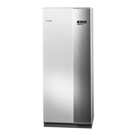
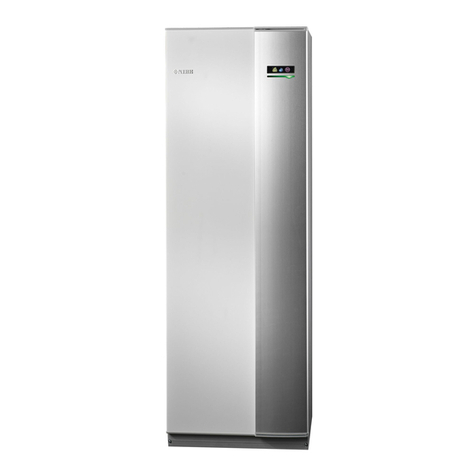
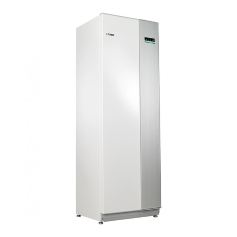
Nibe F205P User manual

InstallatIon and MaIntenance InstructIons
NIBETM F205P
1 x 230 V uK
Mos GB 1124-1
nIBetM F205P
031977
LEK
2
31
20 100
40 80
60
°C
0 120
T
G

LEK
Fighter310PFighter310P
LEK
Fighter310PFighter310P
LEK
Fighter310P
Fighter310P
LEK
Fighter310P
Fighter310P
1
3
4
5
2
LEK
Fighter310PFighter310P
LEK
Fighter310PFighter310P
LEK
Fighter310P
Fighter310P
LEK
Fighter310P
Fighter310P
1
3
4
5
2

1
F205P
Contents
For home Owners
General __________________________________ 2
System description _______________________ 3
System diagram ___________________________________ 3
Principle of operation ______________________________ 3
Front panel ______________________________ 4
Functions on the front panel ______________ 4
Front panel, supplied clock thermostat _____ 5
Front panel’s functions ____________________ 5
Settings _________________________________ 6
Maintenance routines ____________________ 7
General __________________________________________ 7
Cleaning the air filter_______________________________ 7
Cleaning the ventilation devices______________________ 8
Pressure gauge____________________________________ 8
Checking the safety valves __________________________ 8
Dealing with malfunctions ________________ 9
Low temperature or a lack of hot water _______________ 9
Low or a lack of ventilation _________________________ 9
Low room temperature _____________________________ 9
High room temperature ____________________________ 9
Switch position ”3” _______________________________ 9
Cleaning the fan __________________________________ 9
Indications on the display __________________________ 10
Lamp “Compressor is operational/alarm” is flashing____ 10
Lamp “Defrosting is operational/check filter” is flashing 10
Lamp ”Defrosting is operational/check filter” is litted___ 10
Resetting the pressostats __________________________ 10
For the Installer
General information for the installer ______ 11
Transport and storage _____________________________ 11
Handling ________________________________________ 11
Installation ______________________________________ 11
Hard water areas _________________________________ 11
Inspection of the installation _______________________ 11
Maximum boiler and radiator volumes _______________ 11
Installing the clock thermostat _____________________ 12
Pipe connections ________________________ 13
General _________________________________________ 13
Pump and pressure drop diagram _________ 14
Cleaning the system _____________________ 14
Tap water connection ____________________ 14
Ventilation connection ___________________ 15
Ventilation flow __________________________________ 15
Kitchen duct_____________________________________ 15
Adjustment______________________________________ 15
Fan diagram _____________________________________ 15
Duct installation__________________________________ 15
Electrical connections ____________________ 16
Connection______________________________________ 16
Setting the fan capacity ___________________________ 16
Connecting fan switch ____________________________ 16
Circulation pump control __________________________ 17
Current, fuse ____________________________________ 17
Immersion heater_________________________________ 17
Connecting the clock thermostat____________________ 17
Commissioning and adjusting ____________ 18
Preparations _____________________________________ 18
Venting the heating system ________________________ 18
Temperature levels________________________________ 20
Hot water temp. _________________________________ 20
Periodic increase _________________________________ 20
Hot water prioritising _____________________________ 20
Service _________________________________ 21
Electrical circuit diagram _________________ 26
List of components ______________________ 29
Dimensions _____________________________ 30
Dimensions and setting-out coordinates______________ 30
Enclosed kit _____________________________ 31
Accessories _____________________________ 31
Technical Data ___________________________ 32
Benchmark checklist _____________________ 34

2F205P
For Home Owners
General
In order to get the ultimate benefit from your heat pump NIBETM F205P you should read through the
For Home Owners section in this Installation and Maintenance Instruction.
F205P is an exhaust air heat pump. This means it utilises energy in ventilation air and uses this energy
for hot water and heating the house. A microprocessor ensures that the heat pump always works effi-
ciently.
For the installation engineer: Please, hand over to the home owner this manual after
finalised installation.
To be filled in when the heat pump has been installed
General
This appliance is not intended for use by persons (including children) with reduced physical, sensory or mental capabilities, or lack of experience and
knowledge, unless they have been given supervision or instruction concerning use of the appliance by a person responsible for their safety. Children
should be supervised to ensure that they do not play with the appliance. Rights to make any design or technical modifications are reserved.
©NIBE 2011.
Benchmark places responsibilities on both manufacturers and installers. The purpose is to ensure that customers are
provided with the correct equipment for their needs, that it is installed, commissioned and serviced in accordance with
the manufacturers instructions by competent persons and that it meets the requirements of the appropriate Building
Regulations. The Benchmark Checklist can be used to demonstrate compliance with Building Regulations and should
be provided to the customer for future reference.
Installers are required to carry out the installation, commissioning and servicing work in accordance with the Benchmark Code of Practice which is av-
ailable from the Heating and Hotwater Industry Council who manage and promote the Scheme.Visit www.centralheating.co.uk for more information.
Manufacter:
NIBE AB
Box 14
Järnvägsgatan 40
285 21 MARKARYD
SWEDEN
Maximum water
supply pressure
16 bar
Immersion heater R50 / 3000W /
230 V
Operating pressure, tap water 6 bar
Expansion vessel, tap water, char-
ge pressure
3,5 bar
Expansion vessel, heating water,
charge pressure
0,5 bar
Pressure reduction valve, setting 3,5 bar
Volume, water heater 170 litres
Mass, unit, filled with water 435 kg
Maximum primary working
pressure (heating side)
2,5 bar
Set opening pressure of
temperature and pressure valve
7 bar
Set opening pressure relief valve 6 bar
Set opening, temperature limiter,
immersion heater
88 °C
Set opening, temerature limiter,
compressor
88 °C
Heating up time from
15 °C to stop temperature for
compressor
7 h 8 min
Re-heating time, 70 % of
total volume (only compressor
working)
4 h 50 min
Benchmark checklist completed
Exhaust air flow and selected fan curve, high speed (Knob R51)
l/s m3/h ....................... Fan curve .............................
Exhaust air flow and selected fan curve, normal speed (Knob R52)
l/s m3/h ....................... Fan curve .............................
Setting the dip switch (S1) on the circuit board (34)
ON: 4 3 2 1
Heat emitter
Radiator .....................................
Underfloor heating coil
Date_________ Signed__________________________________

3
F205P
For Home Owners
System description
Principle of operation
F205P comprises an electric boiler with a stainless steel
water heater and a heat pump which recovers energy
from the ventilation air. The recovered energy is supplied
to the heat pump. The heat pump must be installed in a
ventilation system intended for mechanical exhaust air. A
DC fan is used in F205P.
The output of the immersion heater is 3 kW. When the
exhaust air at room temperature passes through the evapo-
rator, the refrigerant evaporates because of its low boiling
point. In this way the heat in the air is transferred to the
refrigerant.
The refrigerant is then compressed in a compressor, caus-
ing the temperature to rise considerably.
The warm refrigerant is led to the condenser. Here the
refrigerant gives off its heat to the boiler water, so that the
temperature of the the refrigerant drops and its phases
changes from gas to liquid. The refrigerant then goes via a
filter to the expansion valve, where the pressure drops and
the temperature is lowered further.
The refrigerant has now completed its circulation and re-
turns to the evaporator.
System description
System diagram
LEK
C
When the room air has
passed through the heat
pump it is discharged. The
temperature of the air has
been significantly reduced as
the heat pump has extracted
the energy in the room air.
G
The air from the kitchen
fan goes directly out into
a separate duct.
B
The warm room
air is fed to F205P
D
F205P supplies the house
with both hot water and
room heating.
E
Outdoor air is drawn into the house.
A
The warm room air is
drawn into the air duct
system.
F
Air is transported from
rooms with outdoor
air devices to rooms
with exhaust air
devices.
FrånluftAvluft
FrånluftAvluft
FrånluftAvluft
EJ ÄNDRAD
Extract air Exhaust air

4F205P
For Home Owners
Front panel
Front panel
Thermometer
Here the boiler temperature is indicated . The value
depends on the cut-out temperature of the immer-
sion heater, the set value for the compressor cut-out
temperature and the hot water taps.
A
Pressure gauge
Here the pressure of the radiator circuit is indicated .
The scale marks go from 0 - 4 bars. Normal pressure
is 0,5 - 1,5 bar.
B
Functions on the front panel
Indicators lamps
Top lamp
Lit Compressor is running.
Flashing Alarming for tripped pressostates or in-
dicating standby mode (Compressor
blocked).
Not lit Compressor is not running.
Midmost lamp
Lit Defrosting is operational.
Flashing Air filter to be cleaned.
Not lit -
Lower lamp
Lit Immersion heater is in operation.
Flashing -
Not lit Immersion heater is not in operation.
D
C
F
E
Switch
with 4 positions 0 - 1 - 2 - 3:
0 Heat pump off.
1 Fan is operational. Compressor and circulation
pump operational on demand.
2 Fan is operational. Compressor, immersion
heater and circulation pump operational on de-
mand.
3 Standby mode. Fan is operational. Compressor
is not operational. Immersion heater and circu-
lation pump operational on demand.
Switch
Pressure gauge
Thermometer Indicator lamps
Hot water priority (hidden) Circulation pump (hidden)
Art.nr. 511077
( )
20 100
40 80
60
C
0 120
T
G
2
1bar 3
04
T
G
ABCD
FE
Hot water prioritising (hidden)
with 3 positions “Auto” - “1” - “0”:
Auto Hot water prioritising Continuously acti-
vated (same function as "1")
1 Hot water prioritising continuously acti-
vated.
0 Hot water prioritising not activated.
Circulation pump (hidden)
with 2 positions “Auto” - “1”:
Auto The circulation pump is controlled on and
off by the control system or clock thermo-
stat.
1 Circulation pump in continuous operation.

5
F205P
For Home Owners
Front panel, clock thermostat
Front panel, supplied clock thermostat
On/Off
Press “ ” once to switch off the thermostat, press
again to restart.
A
Operating mode
The operating mode that the heat pump is to use is
selected here.
Auto
M
: In this mode the heat pump operates ac-
cording to your own settings. You set which temper-
ature you want indoors during day and night.
Day
M
: In this mode you get the setting for day
temperature for the entire day.
Night
M
: In this mode you get the setting for night
temperature for the entire day.
Manual: (no symbol) In this mode the set tempera-
tures are not used. Press
M
or
M
to increase or
decrease the temperature indoors.
B
Front panel’s functions
Display
First row: Week day.
Second row: Operating mode day
M
, operating
mode auto
M
, heating on
M
.
Third row: Actual indoor temperature (RT) or set in-
door temperature (SET), clock
Fourth row: Actual fan speed, operating mode
night
M
.
Timer
Set current time and date here.
Increase/decrease
These buttons are used to increase or decrease a
value.
D
CF
E
The indoor temperature is regulated using a room thermostat. When the temperature in the accommodation is the same as
the temperature set on the room thermostat, the circulation pump in the heat pump stops.
To set different intervals with a temperature change, we recommend the supplied clock thermostat. For instructions on how
to set times and temperatures, see section "Settings".
M
Increase/decrease
Fan speed
On/Off Operating mode Timer
Display
F
E
D
C
B
AFirst row
Second row
Third row
Fourth row
Fan speed
Select the fan speed here: high
M
, normal
M
and
auto (no symbol).
If normal
M
or high
M
is selected, you return to
the previous setting after one hour.
If normal
M
or auto is selected, the fan runs at low
speed when the compressor has stopped and rotates
up to speed when the compressor is in operation.

6F205P
For Home Owners
Settings
Set actual time and weekday
1. Press the timer button once
M
. The first two digits in
the clock start to flash.
2. Use
M
or
M
to set the hours. Save the settings by
pressing the timer button once.
3. Use
M
or
M
to set the minutes. Save the settings by
pressing the timer button once.
4. Use
M
or
M
to set the weekday. Save the settings by
pressing the timer button once.
Changing the indoor temperature
A water borne heating system has a certain inertia. This
means that it can take several hours from when the
change was made until the desired temperature in the ac-
commodation is achieved. The size of the house, outdoor
temperature, hot water usage during the time etc. affects
how long the change takes.
E.g. You change the 05:00 setting of the clock thermostat
from 17 °C to 20°C. F205P starts to increase the tempera-
ture but it can take several hours for the heat pump to
achieve the desired change.
At 08:00 you change the setting again, from 20 °C to
17°C. The heat pump then starts to send out cooler wa-
ter to the heating system but it can take several hours be-
fore the water has cooled enough to achieve the desired
temperature.
Programme operating mode
Start by making settings for Monday to Friday:
SET 1 means period 1, SET 2 means period 2.
1. Hold in the timer button
M
until SET 1 appears in the
display.
2. Set the time at which you want period 1 to start to
apply. Set the time in the same way as you set the
clock previously, using
M
or
M
and the timer button.
3. Set the temperature you want indoors during period
1 by pressing
M
or
M
. Save the settings by pressing
the timer button once.
4. Set the time at which you want the period 1 setting
to stop being applied. Set the time in the same way
as you set the clock previously, using
M
or
M
and the
timer button.
5. Set the temperature you want indoors between peri-
ods 1 and 2 by pressing
M
or
M
. Save the settings by
pressing the timer button once.
6. SET 2 now appears in the display. Set the time at
which you want period 2 to start to apply. Set the
time in the same way as you set the clock previously,
using
M
or
M
and the timer button. The temperature
will be the same as you selected in period 1.
7. Set the time at which you want the period 2 setting
to stop being applied. Set the time in the same way
as you set the clock previously, using
M
or
M
and the
timer button.
Now make settings for Saturday and Sunday:
1. This is done in the same way as setting the tempera-
tures for weekdays (repeat steps 2-7).
Change operating mode
Press operating mode button (M) to switch between auto,
day, night and manual mode. Confirm using the timer but-
ton
M
.
If you want one indoor temperature during the daytime
and another indoor temperature during the night select
operating mode auto
M
.
If you want the day temperature for 24 hours select
M
and if you want the night temperature for 24 hours select
M
.
To change temperature at any point during the day, select
the manual mode. If the temperature in the accommoda-
tion is too low or too high, press
M
or
M
to increase or
decrease the temperature. Approximately 30 seconds after
the last button push, the thermostat returns to showing
the actual room temperature.
°C
Tid
17
18
19
20
08:00 09:00 10:00 11:00 12:0004:00 05:00 06:00 07:00
Inställd rumstemperatur
Verklig rumstemperatur
Settings
Time
Set room temperature
Actual room temperature
°C
17
18
19
20
12 14 16 18 20 22 2404 06 08 10
Inställd rumstemperatur
Tid
SET 1 SET 2
Time
Set room temperature

7
F205P
For Home Owners
Maintenance routines
General
The heat pump and its ventilation ducting require some
regular maintenance when the following points should be
checked.
The numbers in brackets refer to the section ”Component
locations”.
Cleaning the air filter
The heat pump air filter (63) should be cleaned regularly,
about four times a year.
1. Set the switch (8) to “0”.
2. The upper service cover is opened by pulling the lower
section outwards. The cover can then be lif-ted off.
3. Pull out the filter cassette (78).
4. Take out the filter and shake/vacuum off any dirt. Do
not use water or other liquids for cleaning.
5. Check that the filter is not damaged. New original fil-
ters can be ordered from a Nibe distributor.
6. Re-assembly takes place in the reverse order.
The cleaning time intervals vary depending on the amount
of dust in the exhaust air. Each third month an indicator
lamp “Midmost lamp” flashing to reminds about cleaning
the air filter. Note that the time will be set to zero by set-
ting the switch to “0”.
LEK
Art.nr. 511077
( )
20 100
40 80
60
C
0 120
T
G
2
1bar 3
04
T
G
Maintenance routines

8F205P
For Home Owners
Maintenance routines
Checking the safety valves
F205P has three safety valves, one for the heating system
and two for the water heater.
The heating system safety valve (52) must be completely
tight, but the hot water safety valve (47) may release some
water after hot water has been used. This is because the
cold water which enters the water heater to replace the
hot water expands when heated, causing the pressure to
rise and the safety valve to open.
Safety valve (104) does not normally release water.
The safety valves must be checked regularly. Check one
valve at a time as follows:
1. Open the valve.
2. Check that water flows through the valve.
3. Close the valve.
4. The heating system may need to be refilled af-
ter checking the safety valve (52), see the section
”Commissioning and adjustment” – ”Filling the heat-
ing system”.
Cleaning the ventilation devices
The building’s ventilation devices should be cleaned regu-
larly with a small brush to keep the correct ventilation.
The device settings must not be changed.
Note! If you take down more than one ventilation device
for cleaning, do not mix them up.
Check that the ventilation opening (84), behind the lower
front cover, is not blocked. Clean if necessary.
Pressure gauge
LEK
2
31
20 100
40 80
60
°C
0 120
T
G
Art.nr. 611830
( )
( )
( )
20 100
40 80
60
ϒC
0 120
T
G
2
1bar 3
04
T
G
Art.nr. 611830
20 100
40 80
60
ϒC
0 120
T
G
2
1bar 3
04
T
G
Art.nr. 611830
20 100
40 80
60
ϒC
0 120
T
G
2
1bar 3
04
T
G
LE
K
2
31
20 100
40 80
60
°C
0 120
T
G
LEK
LEK
LEK
( )
Auto
1
2
31
20 100
40 80
60
C
0 120
T
G
2
1bar 3
04
T
G
( )
Auto
1
2
31
20 100
40 80
60
C
0 120
T
G
2
1bar 3
04
T
G
Gammal
( )
Auto
1
2
31
20 100
40 80
60
C
0 120
T
G
2
1bar 3
04
T
G
Alternativ 2Alternativ 1
LEK
LEK
( )
Auto
1
2
31
20 100
40 80
60
C
0 120
T
G
2
1bar 3
04
T
G
( )
Auto
1
2
31
20 100
40 80
60
C
0 120
T
G
2
1bar 3
04
T
G
Gammal
LEK
LEK
LEK
( )
Auto
1
2
31
20 100
40 80
60
C
0 120
T
G
2
1bar 3
04
T
G
( )
Auto
1
2
31
20 100
40 80
60
C
0 120
T
G
2
1bar 3
04
T
G
( )
Auto
1
2
31
20 100
40 80
60
C
0120
T
G
2
1bar 3
04
T
G
Jättegammal modell
Gammal modell
Åter-
ledning
radiatorer
8
31 32
94
86
30
Fram-
ledning
radiatorer
9
6
11
18
59
16
17
44
70
5
78
27
36
33
20
58
108
52
96
109
97
42
62
48
63
87
65
99
Åter-
ledning
radiatorer
k.v.v.v.
41
35
51
80
71 50
84
98
85
43
53
1
k.v.
v.v.
Blaha blaha
och annat
trams
Åter-
ledning
radiatorer
Blaha blaha
och annat
trams
103
49
88
25
104
148
73
95
Åter-
ledning
radiatorer
8
31 32
86
30
9
6
11
18
59
16
44
5
19
78
27
36
33
58
108
52
96
109
97
42
62
48
63
87
65
99
k.v.v.v.
41
355180507974 47
43
1
k.v.
v.v.
Blaha blaha
och annat
trams
Åter-
ledning
radiatorer
Blaha blaha
och annat
trams
49
88
25
104
73
95
19
47
66 149 151
74 150
LEK
LEK
LEK
( )
Auto
1
2
31
20 100
40 80
60
C
0 120
T
G
2
1bar 3
04
T
G
( )
Auto
1
2
31
20 100
40 80
60
C
0 120
T
G
2
1bar 3
04
T
G
( )
Auto
1
2
31
20 100
40 80
60
C
0120
T
G
2
1bar 3
04
T
G
Jättegammal modell
Gammal modell
Åter-
ledning
radiatorer
8
31 32
94
86
30
Fram-
ledning
radiatorer
9
6
11
18
59
16
17
44
70
5
78
27
36
33
20
58
108
52
96
109
97
42
62
48
63
87
65
99
Åter-
ledning
radiatorer
k.v.v.v.
41
35
51
80
71 50
84
98
85
43
53
1
k.v.
v.v.
Blaha blaha
och annat
trams
Åter-
ledning
radiatorer
Blaha blaha
och annat
trams
103
49
88
25
104
148
73
95
Åter-
ledning
radiatorer
8
31 32
86
30
9
6
11
18
59
16
44
5
19
78
27
36
33
58
108
52
96
109
97
42
62
48
63
87
65
99
k.v.v.v.
41
355180507974 47
43
1
k.v.
v.v.
Blaha blaha
och annat
trams
Åter-
ledning
radiatorer
Blaha blaha
och annat
trams
49
88
25
104
73
95
19
47
66 149 151
74 150
47
104
LEK
LEK
LEK
( )
Auto
1
2
31
20 100
40 80
60
C
0 120
T
G
2
1bar 3
04
T
G
( )
Auto
1
2
31
20 100
40 80
60
C
0 120
T
G
2
1bar 3
04
T
G
( )
Auto
1
2
31
20 100
40 80
60
C
0120
T
G
2
1bar 3
04
T
G
Jättegammal modell
Gammal modell
Åter-
ledning
radiatorer
8
31 32
94
86
30
Fram-
ledning
radiatorer
9
6
11
18
59
16
17
44
70
5
78
27
36
33
20
58
108
52
96
109
97
42
62
48
63
87
65
99
Åter-
ledning
radiatorer
k.v.v.v.
41
35
51
80
71 50
84
98
85
43
53
1
k.v.
v.v.
Blahablaha
ochannat
trams
Åter-
ledning
radiatorer
Blahablaha
ochannat
trams
103
49
88
25
104
148
73
95
Åter-
ledning
radiatorer
8
31 32
86
30
9
6
11
18
59
16
44
5
19
78
27
36
33
58
108
52
96
109
97
42
62
48
63
87
65
99
k.v.v.v.
41
355180507974 47
43
1
k.v.
v.v.
Blahablaha
ochannat
trams
Åter-
ledning
radiatorer
Blahablaha
ochannat
trams
49
88
25
104
73
95
19
47
66 149 151
74 150
LEK
LEK
LEK
( )
Auto
1
2
31
20 100
40 80
60
C
0 120
T
G
2
1bar 3
04
T
G
( )
Auto
1
2
31
20 100
40 80
60
C
0 120
T
G
2
1bar 3
04
T
G
( )
Auto
1
2
31
20 100
40 80
60
C
0120
T
G
2
1bar 3
04
T
G
Jättegammal modell
Gammal modell
Åter-
ledning
radiatorer
8
31 32
94
86
30
Fram-
ledning
radiatorer
9
6
11
18
59
16
17
44
70
5
78
27
36
33
20
58
108
52
96
109
97
42
62
48
63
87
65
99
Åter-
ledning
radiatorer
k.v.v.v.
41
35
51
80
71 50
84
98
85
43
53
1
k.v.
v.v.
Blaha blaha
och annat
trams
Åter-
ledning
radiatorer
Blaha blaha
och annat
trams
103
49
88
25
104
148
73
95
Åter-
ledning
radiatorer
8
31 32
86
30
9
6
11
18
59
16
44
5
19
78
27
36
33
58
108
52
96
109
97
42
62
48
63
87
65
99
k.v.v.v.
41
355180507974 47
43
1
k.v.
v.v.
Blaha blaha
och annat
trams
Åter-
ledning
radiatorer
Blaha blaha
och annat
trams
49
88
25
104
73
95
19
47
66 149 151
74 150
52
The pressure gauge shows the pressure in the heating sys-
tem. The pressure should be between 0.5 and 1.5 bar.

9
F205P
For Home Owners
Dealing with malfunctions
In all correspondence with NIBE
state the serial number
______________
Note!
Low temperature or a lack of hot water
• Large amounts of hot water were used.
• Circuit or main MCB tripped.
• Possible earth circuit-breaker tripped.
• Wrong mode chosen on power switch (8).
• Temperature limiter (6) tripped. Contact service.
• Thermostat (3) for immersion heater set too low.
High room temperature
• Clock thermostat setting not correct
Cleaning the fan
The fan needs to be cleaned, if it is noisy. Call your installa-
tion engineer.
Switch position 3
When the switch is set to “3”, the compressor is not op-
erational. The fan and the immersion heater are operation-
al. Normally the immersion heater lamp is lit in mode “3”,
when the immersion heater is operational.
A possible fault on the printed circuit card can cause the
disappearance of the number display. However, the immer-
sion heater is still operational, if the thermostat has not
cut-out the immersion heater.
Low or a lack of ventilation
• Defrost mode - lamp flashing - see chapter “Lamp
indications”.
• Filter (63) clogged (possible replace).
• Exhaust air device blocked or throttled down too
much.
• Circuit or main MCB tripped.
• RCD (if fitted) tripped.
• Setting of the manual fan switch (if mounted) is incor-
rect.
Low room temperature
Dealing with malfunctions
In the event of malfunction or operating disturbances first check the points below:
Art.nr. 611830
( )
( )
( )
20 100
40 80
60
ϒC
0 120
T
G
2
1bar 3
04
T
G
Art.nr. 611830
20 100
40 80
60
ϒC
0 120
T
G
2
1bar 3
04
T
G
Art.nr. 611830
20 100
40 80
60
ϒC
0 120
T
G
2
1bar 3
04
T
G
LEK
2
31
20 100
40 80
60
°C
0 120
T
G
• Circuit or main MCB tripped.
• Possible earth circuit-breaker tripped.
• Tripped temperature limiter (6). Contact service
• Incorrectly set value on the room thermostat.
• Circulation pump (16) stopped. See the section
“Dealing with malfunctions” – “Starting the pump”.
• Air in the boiler or system.
• Close valves (44) and (50) in the radiator circuits.
• Too low pre-pressure in the expansion vessel, contact
the installer.

10 F205P
For Home Owners
Dealing with malfunctions
Lamp “Compressor is operational/alarm” is
flashing
• A fault has occured in the cooling circuit. (One of the
pressostates has cut-out).
• Mode “3” is set.
When the cause of the fault has been put right, the fault
code must be cleared from the display by switching the
heat pump off and on again.
Lamp “Defrosting is operational/check filter”
is flashing
Air filter has to be cleaned (lamp flashing each third
month). After cleaning the filter, the fault code must be
cleared from the display by switching the heat pump off
and on again.
Lamp ”Defrosting is operational/check filter”
is litted
When there is too much ice on the evaporator, defrosting
takes place. After this, the compressor starts automati-
cally if heating is needed. Frequent defrosting is a sign of
clogged ventilation devices or dirty filters.
See ”Maintenance routines” – ”Cleaning air filters”.
Resetting the pressostatsIndications on the display
Art.nr. 511077
( )
20 100
40 80
60
C
0 120
T
G
2
1bar 3
04
T
G
In all correspondence with NIBE
state the serial number
______________
Note!
LEK
2
31
20 100
40 80
60
°C
0 120
T
G
High pressure pressostat
LEK
LEK
LEK
( )
Auto
1
2
31
20 100
40 80
60
C
0120
T
G
2
1bar 3
04
T
G
( )
Auto
1
2
31
20 100
40 80
60
C
0 120
T
G
2
1bar 3
04
T
G
( )
Auto
1
2
31
20 100
40 80
60
C
0 120
T
G
2
1bar 3
04
T
G
Jättegammal modell
Gammal modell
LEK
LEK
LEK
( )
Auto
1
2
31
20 100
40 80
60
C
0120
T
G
2
1bar 3
04
T
G
( )
Auto
1
2
31
20 100
40 80
60
C
0 120
T
G
2
1bar 3
04
T
G
( )
Auto
1
2
31
20 100
40 80
60
C
0 120
T
G
2
1bar 3
04
T
G
Jättegammal modell
Gammal modell
LEK
LEK
LEK
( )
Auto
1
2
31
20 100
40 80
60
C
0120
T
G
2
1bar 3
04
T
G
( )
Auto
1
2
31
20 100
40 80
60
C
0 120
T
G
2
1bar 3
04
T
G
( )
Auto
1
2
31
20 100
40 80
60
C
0 120
T
G
2
1bar 3
04
T
G
Jättegammal modell
Gammal modell
LEK
LEK
LEK
( )
Auto
1
2
31
20 100
40 80
60
C
0120
T
G
2
1bar 3
04
T
G
( )
Auto
1
2
31
20 100
40 80
60
C
0 120
T
G
2
1bar 3
04
T
G
( )
Auto
1
2
31
20 100
40 80
60
C
0 120
T
G
2
1bar 3
04
T
G
Jättegammal modell
Gammal modell
To reset a tripped pressostat, press the button on top of it;
see figure. The pressostats are within reach by opening the
filter box.
Low pressure pressostat. Normally this
pressostat resets automatically, so it
does not have a resetbutton.

11
F205P
For the Installer
General information for the installer
Handling
The heat pump contains highly inflamma-
ble refrigerant. Special care should be exer-
cised during handling, installation, service,
cleaning and scrapping to avoid damage
to the refrigerant system and in doing so
reduce the risk of leakage.
Transport and storage
The heat pump should be transported and stored vertically
in the dry. The F205P may however be carefully laid on its
back when being moved into a building.
Installation
The heat pump should preferably be erected with its back
about 10 mm from an outside wall in a utility room or
similar, to minimise noise nuisance. If this is not possible,
avoid placing it against a wall behind a bedroom or other
room where noise may be a problem. Irrespective of the
placement the wall should be sound insulated. NOTE! The
distance between the heat pump and the wall should be at
least 10 mm.
Route pipes so they are not fixed to an internal wall that
backs on to a bedroom or living room.
An area of approximately 15 cm is required on the left side
of the heat pump, at the temperature and pressure valve
(104) to enable access to the valve.
Hard water areas
Normally it is no problem to install F205P in hard water ar-
eas since the maxing working temperature is 60 °C.
Inspection of the installation
Current regulations require the heating installation to be
inspected before it is commissioned. The inspection must
be carried out by a suitably qualified person. The above ap-
plies to installations with a closed expansion vessel. A new
inspection must be made when changing the heat pump
or the expansion vessel.
Maximum boiler and radiator volumes
The volume of the ex-
pansion vessel (85) is
12 litres and it is pressu-
rised as standard to 0.5
bar (5 mwp). As a result,
the maximum permit-
ted height “H” between
the vessel and the high-
est radiator is 5 metres;
see figure. If the stand-
ard initial pressure in
the pressure vessel is not
high enough it can be in-
creased by adding air via
the valve in the expan-
sion vessel. The initial
pressure of the expansion vessel must be stated in the in-
spection document.
Any change in the initial pressure affects the ability of the
expansion vessel to handle the expansion of the water. The
maximum system volume excluding the boiler is 106 litres at
the above initial pressure.
H
Since a waterfilled F205P weighs roughly
435 kilos, the floor must stand such a
weight.
Note!
+2
0
-2
1
R
0
HMflow
49(50)°C
Hotwater
51°C
+2
0
-2
1
R
0
HMflow
49(50)°C
Hotwater
51°C
+2
0
-2
1
R
0
HMflow
49(50)°C
Hotwater
51°C
+2
0
-2
1
R
0
HMflow
49(50)°C
Hotwater
51°C

12 F205P
For the Installer
Put the connected thermostat onto the back panel in the
wall, then fix it with the two screws in the packing box.
Put the cover with 30 degree angle, then fix the up two
clips;
Push the places of the two down clips, fix the cover, and
finish the installation.
Open the main control panel. Put the screwdriver
(3.5mm) into the block 4mm along the bevel. Prize up,
open the clips.
Take off the wires.
As per wiring diagram, connect it with terminals, fixed by
the screwdriver.
Be sure to connect all the wires as per the
wiring diagrams and keep it away from
water, mud and other material so as to
prevent the unit being spoiled!
Note!
Installing the clock thermostat

13
F205P
For the Installer
Pipe connections
Pipe connections
General
This installation is subject to building regulation approval,
notify the Local Authority of intention to install.
Use only replacement parts recommended by the manufac-
turer.
Pipe installation must be carried out in accordance with
current norms and directives.
All domestic hot water circuits, connections and fittings
must be in accordance with the relevant standards and wa-
ter supply regulations. It should also be in accordance with
the relevant requirements of the Local Authority and the
Building Regulations relevant to the location of installation.
BS 6700 Services supplying water for domestic use within
buildings and their cartilages.
Water Supply (Water Fitting) Regulations 1999 or The
Water Bylaws 2000 (Scotland).
The installation of the heat pump should follow best prac-
tice as covered in the following:
BS 5449 Forced circulation hot water central heating sys-
tems for domestic premises.
BS 15450 Heating systems in buildings – Design of heat
pump heating systems.
The system requires a low-temperature dimensioning of
the radiator circuit. At DUT, the highest recommended
500 mm maximum
300 mm
minimum
Tundish
Metal discharge pipe from
temperature relief valve to tundish.
Metal discharge pipe from tundish,
with continous fall.
Discharge below
fixed grating.
Fixed grating
Trapped gulle
y
Possible wall
Safety device
(e.g. temperature
relief valve).
Valve outlet
size Minimum size
of discharge
pipe
Minimum size of discharge
pipe from tundish Maximum resistance allowed,
expressed as a lenght of straight
pipe (i.e. no elbows or bends)
Resistance created by
each elbow or bend
G1/2 15 mm 22 mm up to 9 m 0,8 m
G1/2 15 mm 28 mm up to 18 m 1,0 m
G1/2 15 mm 35 mm up to 27 m 1,4 m
<G3>/4 22 mm 28 mm up to 9 m 1,0 m
<G3>/4 22 mm 35 mm up to 18 m 1,4 m
<G3>/4 22 mm 42 mm up to 27 m 1,7 m
G1 28 mm 35 mm up to 9 m 1,4 m
G1 28 mm 42 mm up to 18 m 1,7 m
G1 28 mm 54 mm up to 27 m 2,3 m
Table sizing of copper discharge pipe for common temper-
ature relief valve outlet sizes.
temperatures are 55 °C on the flow line and 45 °C on the
return line.
When the circulation pump is running, the flow in the
radiator circuit must not be completely stopped. When
connecting to a system with thermostats on all radiators, a
relief valve must be fitted, or some of the thermostats must
be removed to ensure sufficient flow.
The total volume is 240 litres, with 170 litres in the water
heater and 70 litres in the boiler section.
The pressure vessel in the F205P is approved for max 9.0
bar (0.9 MPa) in the water heater and 2.5 bar (0.25 MPa)
in the double shell section.
Overflow water from the evaporator collection tray and
safety valves goes via non-pressurised collecting pipes to a
drain so that hot water splashes cannot cause injury. The
outlet of the overflow pipe should be visible and clearly
away from any electrical components. Likewise should the
discharge pipes (tundishes), drain valves and motorised val-
ves be positioned clearly away from any electrical compo-
nents. These non-pressurised collecting pipes shall not be
used for anything else. A discharge pipe from the tundish
(108) connected to the expansion reliet valve (47) (safety
valve) shall also be connected to a drain in the same way.
No valve should be fitted between the pressure reduction
valve (expansion valve) and the storage cylinder.
Do not use collection funnel (99) to dis-
charge pipes from tundish (109).
Note!
This installation is subject to building regu-
lation approval, notify the local Authority
of intention to install.
Note!
Use only manufacturer’s recommended
replacement parts.
Note!

14 F205P
For the Installer
Pipe connections
Pump and pressure drop diagram
Tap water connection
Hot and cold water are connected to pos (74) (hot water)
and (73) (cold water).
The enclosed expansion vessel (107) must be connected to
the hot water system.
The heat pump should be supplemented with an electric
water heater if a bubble pool or other significant consumer
of hot water is installed.
Cleaning the system / Flushing out of
the hot water and the heating sys-
tem
The pipe work must be flushed before the heat pump is
connected, so that any contaminants do not damage the
components parts.
After flushing, an inhibitor should be used for long term
corrosion protection. Ensure all cleanser is removed from
the system before adding the inhibitor.
NIBE Energy Sytems Limited recommends Fernox and
Sentinel water treatment products for heating and cooling
systems.
Pump and pressure drop diagram
Tryck
(kPa)
Flöde (l/s)
00 0,05 0,1 0,15 0,2 0,25
10
20
30
40
50
60
70
I
II
III
Pressure
(kPa)
Flow l/s
Effekt
(w)
Flöde (l/s)
00 0,05 0,1 0,15 0,2 0,25
10
20
30
40
50
60
70
I
II
III
Output
(w)
Flow l/s
LEK
LEK
Switch
Setting the pump speed
To set the correct flow in the heating system, the correct
speed must be set for the circulation pump in the differ-
ent operating conditions.
Compare the planned heating with the available capac-
ity for the circulation pump (16) and set the lowest pos-
sible pump speed.
You set the speed for the circulation pump with the help
of the switch on the pump. Choose speed I, II or III. You
can see the chosen speed to the left, above the switch.
The display to the right, above the switch, should not be
lit.

15
F205P
For the Installer
A duct in a masonry chimney stack must
not be used for extract air.
Note!
Ventilation connection
Duct installation
To prevent fan noise being transferred to the exhaust air
devices, it may be a good idea to install a silencer in the
duct. This is especially important if there are exhaust air
devices in bedrooms. Because the heat pump contains a
flammable refrigerant in the form of propane (R290), the
air ducting system must be earthed. This is done by making
a sound electrical connection to the exhaust air duct and
extract air duct using the two earthing cables supplied. The
cables must then be connected to the earthing studs on
top of the top cover.
Duct connections should be made via flexible hoses, which
must be installed so that they are easy to replace. The
extract air duct is to be insulated using diffusion-proof
material along its entire length. Provision must be made
for inspection of the duct. The exhaust air duct should be
fitted with an adjustment damper. Make sure that there are
no reductions of cross-sectional area in the form of creases,
tight bends etc, since this will reduce the ventilation capac-
ity. All joins in the ducting must be sealed and pop-riveted
to prevent leakage.
The air duct system should, at a minimum, be of air tight-
ness class B.
Ventilation connection
Fan diagram
The diagram below shows the available ventilation capac-
ity.
Luftkapacitet F200P uk
0
50
100
150
200
250
300
350
400
450
050 100 150 200 250 300 350 450400
0
50
100
150
200
E
D
F
G
HI
I
J
J
Airflow, m3/h
Available static pressure, Pa
Output, W
Ventilation flow
Ventilation system should be installed and commissioned
in accordance with the UK Building Regulations Part F
England and Wales and Chapter 3.4, Scotland.
F205P is connected so that all ventilation air except the
kitchen fan passes the evaporator (62) in the heat pump.
For optimum heat pump performance the ventilation flow
must not be less than 100 m ³/h (28 l/s) when the com-
pressor is in operation. F205P is equipped with a ventila-
tion opening in the base. As a result, an air flow of about
5 m3/h.
(1,4 l/s) is taken directly from the room where the heat
pump is installed. Changing the ventilation capacity is
described under “Electrical connection - Setting the fan
capacity”. The curve’s designation refers to the position of
the knobs R51 and R52 on the circuit board (34).
Connect the supplied clock thermostat to select between
normal or high ventilation.
Kitchen duct
Duct from Cooker Hoods must not be connected to the
F205P.
Adjustment
To obtain the necessary air exchange in every room of the
house, the exhaust air devices must be correctly positioned
and adjusted. An incorrect ventilation installation may lead
to reduced heat pump efficiency and thus poorer operat-
ing economy, and may result in damage to the house.

16 F205P
For the Installer
Connection
The heat pump must be permanently connected to a
230V ac 50Hz supply.
All system components shall be of an approved type and
all wiring to current I.E.E wiring regulations.
External wiring must be correctly earthed, polarised and
in accordance with the relevant standards: Currently this
is BS 7671.
Disconnect the heat pump before insulation testing the
house wiring.
The supply (230 V~ 1-phase + N) for the heat pump must
be connected to terminal (9) via a cable clamp.
The connection of the heat pump must be done under the
supervision of a qualified electrician.
The heat pump installation implies a contact breaker.
The vinyl-pipe on the right side may be used as cable entry
conduit.
The temperature limiter (6) cuts off the supply to the im-
mersion heater if the temperature rises to 88 °C; it can be
manually reset by pressing the button on the temperature
limiter.
The temperature limiter (7) for the compressor cuts off the
supply to the compressor if the temperature rises to 88 °C;
it can be manually reset by pressing the button on the tem-
perature limiter.
Setting the fan capacity
The switch (8) must not be moved from “0”
until the boiler has been filled with water
Otherwise the temperature limiter, thermo-
stat, compressor and the immersion heater
can be damaged.
Note!
Reset the temperature limiters,
it may have tripped during transport.
Note!
The electrical installation, wiring and any
service work must be done in strict con-
formity to current regulations under the
supervision of a qualified electrician.
Note!
Electrical connections
R51 R52
12345678910
11
Klocktermostat
Växlande
omkopplare
12
345678910
LN
L1 N1 PE
LVCVal FC MedHiN
11
9
Inkoppling med
klocktermostat
Inkoppling med
växlande omkopplare
Select the ventilation capacity by turning the knob on the
circuit board (34) to the desired setting. See the illustration
“Ventilation connection” – “Fan diagram”.
The positions are as follows:
Knob R51: High ventilation, compressor in operation.
Knob R52: Normal ventilation, compressor stopped.
Connecting fan switch
Connect the supplied clock thermostat to select between
normal or high ventilation.
Closing function between “8” and “9” means normal fan
speed.
Closing function between “9” and “10” means high fan
speed.
Connect the fan switch according to the image below.
Connecting with
clock thermostat
Clock thermostat

17
F205P
For the Installer
Electrical connections
Connecting the clock thermostat for the circ-
ulation pump
Circulation pump control
Normally a room thermostat is used controlling the starts
and stops of the circulation pump. When the set room
temperature is reached, the circulation pump is stopped
and starts again when the temperature drops. For connec-
tion see diagram “Electrical connections” – “Connecting
the room thermostat”.
The circulation pump can even be operated manually. No
room thermostat will be connected. Instead the circulation
pump is operated by the switch (18) on the front panel.
The mode “Auto” does not permit any operation of the
circulation pump if no room thermostat is connected. The
switch in position “On” permits permanent operation of
the circulation pump.
Current, fuse
The maximum current is 16,7 Ampere. Therefore a 20
Ampere fuse shall be used. NOTE! Relevant electrical stand-
ards must be considered.
Immersion heater
F205P is delivered with a 3 kW immersion heater (1). It is
started and stopped via the microproessor card (34). If a
failure occurs there is a temperature limiter (6) (thermal
cut-out) that is stopping the immersion heater. An immer-
sion heater without a temperature limiter is not allowed to
be mounted.
Connect the supplied clock thermostat to terminal block
(9) and (11) according to the image below.
Set switch, circulation pump (18) to ”auto”.
Set the clock thermostat according to the ”Settings” sec-
tions.
Klocktermostat
9
LN L1 N1 PE
LVCVal FC MedHiN
Clock thermostat

18 F205P
For the Installer
Commissioning and adjusting
Preparations
When connecting to a system with thermostats on all ra-
diators, a relief valve must be fitted, or some of the ther-
mostats must be removed to ensure sufficient flow.
Check that the switch (8) is set to “0”.
Check that valves (44) and (50) are fully open and that the
temperature limiter (6) has not tripped (press firmly the
knob). F205P is supplied with a limiting valve (5) mounted
on the outlet pipe. This one allows to set a maximum out-
let temperature in order to protect the floor in an existing
floor heating system. This valve is adjustable between 36
and 60 °C. Factory setting is 38 °C which corresponds to a
value between 1 and 2 on the knob. To change this value,
remove the protective cover and turn the settings knob
(19) clockwise for a lower temperature and anticlockwise
for a higher temperature to the desired setting.
Filling the water heater and the heating sys-
tem
1. The water heater is filled by opening a hot water tap.
When water comes out of the hot water tap this can
be closed.
2. Connect enclosed flexible hose (147) between connec-
tion (149) and connection (150) (the hose is mounted
at the unit when this is delivered). Open filling valves
(151) and (49). The boiler part of the heat pump and
the radiator system are now filled with water.
Venting the heating system
• Vent the electric boiler through the safety valve (52)
and the rest of the heating system through the rel-
evant venting valves.
• Keep topping up and venting until all air has been re-
moved and the pressure is correct.
3. After a while the pressure gauge (42) will show ris-
ing pressure. When the pressure reaches 2.5 (bar)
(approx. 25 mvp) a mixture of air and water starts to
emerge from the safety valve (52). The filling valves
(151) and (49) are then closed.
4. Turn the safety valve (52) until the boiler pressure
reaches the normal working range (0.5 - 1.5 bar).
5. The flexible hose between connection (149) and con-
nection (150) must not be connected during opera-
tion. Therefore, remove it before the heat pump is
started.
LEK
LEK
LEK
( )
Auto
1
2
31
20 100
40 80
60
C
0 120
T
G
2
1
bar
3
04
T
G
( )
Auto
1
2
31
20 100
40 80
60
C
0 120
T
G
2
1
bar
3
04
T
G
( )
Auto
1
2
31
20 100
40 80
60
C
0 120
T
G
2
1
bar
3
04
T
G
Åter-
ledning
radiatorer
8
31 32
94
86
30
Fram-
ledning
radiatorer
9
11
18
59
78
27
36
33
20
58
108
52
96
109
97
42
62
48
63
87
65
99
Åter-
ledning
radiatorer
k.v.v.v.
41
35
51
80
71 50
84
98
85
43
53
1
k.v.
v.v.
Blaha blaha
och annat
trams
Åter-
ledning
radiatorer
Blaha blaha
och annat
trams
103
88 6
25
104
148
73
95 19
47
66 149 151
74 150
Åter-
ledning
radiatorer
8
31 32
86
30
11
18
59
78
27
36
33
20
58
108
52
96
109
97
42
62
48
63
87
65
99
41
51
80
50
43
k.v.
v.v.
Blaha blaha
och annat
trams
Åter-
ledning
radiatorer
Blaha blaha
och annat
trams
25
104
148
47
149 151
74 150
7 43
94
1
88 6
7 43
6
3
9
6
3
Åter-
ledning
radiatorer
k.v.
v.v.
Blaha blaha
och annat
trams
Åter-
ledning
radiatorer
Blaha blaha
och annat
trams
16
44
70
35
16
44
70
5
19
5
When filling, after the heat pump is
started, the flexible hose must be installed
between connection (149) and (150).
Note!
Other manuals for F205P
2
Table of contents
Other Nibe Heat Pump manuals

Nibe
Nibe Fighter 2005 Original operating manual

Nibe
Nibe F1145 series Quick start guide

Nibe
Nibe DEW 40 User guide

Nibe
Nibe S1156 User guide

Nibe
Nibe S735 User manual

Nibe
Nibe F470 User manual

Nibe
Nibe F370 User manual

Nibe
Nibe F2016 User guide

Nibe
Nibe SMO 10 Original operating manual

Nibe
Nibe CLIMATEMASTER TRT Series Owner's manual
Popular Heat Pump manuals by other brands

Heat Controller
Heat Controller RPHE-093G Series Installation & operation manual

Haier
Haier AW052MUCHA installation manual

Trane
Trane 2TTX4018B Installer's guide

Fujitsu
Fujitsu Waterstage WOYG140LCTA manual

Bard
Bard Q24H1D installation instructions

Viessmann
Viessmann Vitocal 242-S Installation and service instructions