Mouser Electronics TMS320C5515 Instruction Manual

USB Cable
TMS320C5515 Evaluation Module
(
EVM
)
Quick Start Installation Guide
Items Required for Setup
+5V Universal
Power Supply AC Power
Cords
C5515 EVM
C5515 EVM Code Composer
Studio DVD
System Requirements
•2 GB of free hard disk space
•Microsoft Windows™ XP/Vista
•Min 1 BG RAM, 2 BG recommended
•Min 1.5 GHz, dual core recommended
•Color Display
•Internet access
•USB port
•DVD Reader
Service and Support
Web http://support.spectrumdigital.com
Description
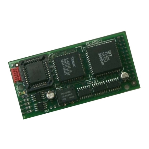
The C5515 Evaluation Module (EVM) is an all-in-one
evaluation platform for the TMS320C5515 Digital Signal
Processor from Texas Instruments. It includes a target
board that can be used as a reference design. Included is
a board specific version of TI's flagship Code Composer
Studio development tools. An on-board JTAG emulator
allows debug from Code Composer Studio through your
PC's USB port.
This kit contains everything you need to get started with TI
DSPs. It can also be used with the full version of Code
Composer Studio and an external JTAG emulator.
©Copyright Spectrum Digital 2010 512706-4001A Page 1 of 4
12502 Exchange Dr., Ste 440, Stafford, TX. 77477 T:281.494.4505, F:281.494.5310 www.spectrumdigital.com

Install EVM Content from the CD-ROM
Note: Install ALL software prior to connecting the
C5515 EVM to the computer !
Note: The user MUST be logged onto windows with
“Administrative Rights” and any anti-virus software
must be disabled during installations. Please
contact your system administrator if help is needed
in this area.
1. Insert the Code Composer Studio (CCS) v4 DVD into
the computer’s DVD drive and wait for the auto-run
application to start. The user prompts will step the
user through the rest of the CCS installation. The
installation will place a CCS icon on your desktop.
2. At this time plug the C5515 EVM into a USB port on
your laptop or PC. Windows will recognize the new
hardware connection and complete the hardware
installation automatically. The C5515 EVM will
enumerate as a DSK5510 as they share emulation
drivers.
3. Launch CCS v4 from the shortcut icon on the desktop.
4. A prompt will appear asking for a workspace location.
Each time CCS starts up the main workspace is the
main working folder for CCS. The default location will
be (on Windows XP) “C:\Documents and
Settings\<user name>\MyDocuments\workspace”. To
have CCS automatically default to the specified
workspace location, select the “Use this as the default
and do not ask again” option.
5. Create a user license. After launching CCS, the user
may be prompted to create a user license to activate
the CCS software. Select the “Activate a License”
option. If prompted click “Use Free Limited License”.
This will re-direct you to the Texas Instruments
website to complete the License creation process.
Alternatively, the “Activate a License” step may be
bypassed temporarily and completed at a later date
by clicking “Evaluate Code Composer Studio for 30
days”.
6. If you receive a prompt that automatic updates are
available select “NO” and proceed, You can get
these updates later after successfully running a CCS
session.
CCS Configuration Instructions
1. Launch CCS v4 from the shortcut on the desktop.
(This was created when CCS v4 was installed).
2. The CCS v4 window will appear. Click the “Target”
menu, then select “New Target Configuration File”.
3. The “New Target Configuration” window will appear.
Enter a file name that describes the emulator
connection and/or Texas Instruments device being
used and click “Finish”. For example:
“EVM5515”.
4. The “Basic” configuration setup window will open in
the CCS v4. Select “Spectrum Digital
DSK-EVM-eZdsp onboard USB Emulator” from the
“Connection” menu. Type “5515” in the “Device” field
and select “EVM5515”, from the list.
5. Click the “Save” button to save the configuration.
6. Click the “View” menu and select “Target
Configurations” to expose the configuration(s) that
have been built or imported. A new tab labeled
“Target Configurations” will become available in the
CCS window.
512706-4001A Page 2 of 4
12502 Exchange Dr., Ste 440, Stafford, TX. 77477 T:281.494.4505, F:281.494.5310 www.spectrumdigital.com

7. Expand the “User Defined” folder. Right-click on the
new configuration that has been created and click
“Launch Selected Configuration”.
8. Click “View->Debug” then click “Target->Connect
Target”. CCS will attempt to connect to the C5515
EVM and run the GEL file. Once the connection is
successful and the GEL file has finished, the console
window will print a message stating
“Target Connection Complete”.
Running the C5515 EVM LED Blink
Demonstration
1. The C5515 EVM must be connected in CCS before
proceeding. If the board is not connected, please refer
to section 4.0 of this guide.
2. Click “File->Import”.
3. When the new window appears, expand “CCS” and
select “Existing CCS/CCE Eclipse Project”. Click
“Next”.
4. Select “Select Root Directory” and click the “Browse”
button. Browse to directory path
“<Install_Dir>\ccsv4\emulation\boards\evm5515_v1\tests\
led”
The default <Install_Dir> is “C:\programfiles\Texas
Instruments”
5. Highlight the “LED” folder and click “OK”. Then click
“finish”
6. Click “View->C/C++Projects”. A new tab will appear in
the CCS v4 window and there should be a LED project
visible.
7. Click “Project->Build Active Project”.
8. When the build is complete, a message will print in the
Console Window.
9. Look in the “C\C++Projects” tab again and expand the
“binaries” folder. There now should be a “led.out” file
listed.
10. Right click on “led.out” and click “Load Program”.
11. Click “Target->Run”. The C5515 EVM “XF” LED
should now blink.
SUPPORT RESOURCES
1. For additional information regarding the
TMS320C5515 family of DSPs please refer to the
following page on the TI web site:
http://tiexpressdsp.com/index.php/C5000
2. Code Composer Studio support is available via a
forum at:
http://community.ti.com/forums/138.aspx
3. More information about other Spectrum Digital
emulators can be found at:
www.spectrumdigital.com
C5515 EVM Hardware Registration
The C5515 EVM hardware can be registered using the on-
line registration process at www.spectrumdigital.com.
Spectrum Digital, Inc. warrants the products it produces
for one (1) year after the date of purchase. For a product
to be considered "in warranty", Spectrum Digital must be
notified of the defect within one (1) year after being
purchased from Spectrum Digital or one of its authorized
resellers. Spectrum Digital is not responsible for accidents,
improper installation of connections, misuse, neglect or
unauthorized modifications. If the product qualifies for
warranty repair Spectrum Digital may repair or replace the
product at its discretion.
512706-4001A Page 3 of 4
12502 Exchange Dr., Ste 440, Stafford, TX. 77477 T:281.494.4505, F:281.494.5310 www.spectrumdigital.com

Debug Hints and Trouble Shooting
1. If installing on Windows XP and your PC is connected
to the internet through a firewall the USB install may
take up to 15 minutes if you let it complete normally.
The work-around for this issue is to simply disconnect
your network cable during the USB hardware install.
2. Some of the Help Files are links to Adobe Acrobat
PDF files. If you intend to access these files you must
have Adobe Acrobat installed on your system.
3. If you want to verify a successful USB driver install,
open your device manager by right clicking on the My
Computer icon on your desktop and selecting
Properties --> HW --> Device Manager. You should
see a new class “SD USB Based Debug Tools” and
one Spectrum Digital TMS320C5510 DSK installed.
4. The Embedded EMU BUSY LED (DS1) beside the
USB connector comes on when power is applied to
the EVM. Do not launch Code Composer until the
LED is off.
Error Messages
Many of the error messages below refer to USB
enumeration issues. The following window will appear
when launching CCS or the Diagnostic Utility indicating
the enumeration status.
1. Message:
Failed: Requires Win98, Win2K or Win XP.
Problem: Your operating system does not support
USB.
2. Message:
Failed: USB device is NOT enumerated or plugged in.
Problem: Windows cannot find the EVM. Check
power and USB Cable.
3. Message:
Failed: Load USB Application.
Problem: Loader could not download the EVM
emulation application. The on-board emulation
controller could be in a bad state. Cycle power on the
EVM.
4. Message:
Failed: USB Channel in use by another app.
Problem: Another application is using the EVM USB
communication channel. Only one application is
allowed to communicate to the EVM over the USB
channel at the same time. Check for active
applications using the Windows Task Manager if open
application is not obvious.
5. Message:
Waiting for USB Enumeration.
Status: This is a status message which indicates that
Code Composer Studio is waiting for communication
with the on-board JTAG emulator to be established.
This should take less than 10 seconds. Do not hit the
close button unless it is clear that something is wrong
(the progress bar runs forever).
RESOURCES
The latest version of the Chip Support Library (CSL)
for the TMS320C5515 is available at:
http://focus.ti.com/docs/toolsw/folders/print/sprc133.html
For more details, please contact you local Texas
Instruments representative or send an email to:
512706-4001A Page 4 of 4
12502 Exchange Dr., Ste 440, Stafford, TX. 77477 T:281.494.4505, F:281.494.5310 www.spectrumdigital.com

Mouser Electronics
Authorized Distributor
Click to View Pricing, Inventory, Delivery & Lifecycle Information:
Spectrum Digital:
702260
Table of contents
Popular Control Unit manuals by other brands

SMART Embedded Computing
SMART Embedded Computing PrAMC-7311 Installation and use

Rockwell Automation
Rockwell Automation Bulletin 193 E1 PLUS Application and Installation

NXP Semiconductors
NXP Semiconductors TWR-56F8400 user manual

Chargery
Chargery BMS16Pro Series manual

HydroAir
HydroAir 20-0242 quick start guide

Eaton
Eaton Power XL SmartWire-DT DX-NET-SWD3 Instruction leaflet

Det-Tronics
Det-Tronics Eagle Quantum Premier EQ3760ASM manual

Keysight Technologies
Keysight Technologies E4461B Assembly instructions

LICHUAN
LICHUAN LCDA2263C user manual

Victaulic
Victaulic KOIL-KIT 799 Series Installation and maintenance instructions

Flowserve
Flowserve NAF ProCap User instruction

REMS
REMS CamSys Instructions for installing