I-KOIL.KITINSTALLATION AND MAINTENANCE INSTRUCTIONS
KOIL-KIT™Coil Pack – Series 799, Series 79V with ATC Valve,
Series 79B with Bypass, and Series 79A with Bypass and ATC Valve
For complete contact information, visit victaulic.com
I-KOIL.KIT 2954 REV F UPDATED 07/2014 Z004799001
VICTAULIC AND KOIL-KIT ARE TRADEMARKS OR REGISTERED TRADEMARKS OF VICTAULIC COMPANY AND/OR ITS AFFILIATED ENTITIES
IN THE UNITED STATES AND/OR OTHER COUNTRIES. © 2014 VICTAULIC COMPANY. ALL RIGHTS RESERVED.
INSTALLING THE BALANCING VALVE DRAIN KIT
NOTICE
• System depressurization is not required for drain kit installation;
however, caution must be taken to ensure that the long pressure/
temperature (PT) port is not loosened prematurely.
*NOTE: New gaskets
must be used.
FLOW
Drainage
Nipple
Gasket*
Gasket*
Cover
Nut
The drain kit (part number K-000-786-CBV) for Series 786, 787, and
78K Balancing Valves is sold separately through Victaulic and comes
with two new gaskets, a drainage nipple, and a nut.
1. Remove the components from the long pressure/temperature (PT)
port, shown in the assembly drawings above. NOTE: The cover with red
holder will be re-used when the drain kit is installed.
2. Install the drain kit components, as shown in the drawing above. The
new gaskets (provided in the kit) must be installed to prevent leakage
from the port. Re-install the cover with red holder onto the nut.
3. Locate the recess under the cover. Insert a 5-mm allen key, and
apply 8 - 14 counterclockwise turns to drain from the PT port.
PRE-SETTING, BALANCING, AND MEASURING
Refer to the applicable installation and setting instructions for the valve
supplied with the KOIL-KIT™Coil Pack.
REPLACEMENT PART INFORMATION
WARNING
• Depressurize and drain the piping system before attempting to
perform any maintenance or replace any components.
Failure to follow this instruction could result in serious personal
injury and/or property damage.
The following parts are sold separately through Victaulic for KOIL-KIT™
Coil Packs. Contact Victaulic with any order requests or questions
regarding these parts.
Hose-End Drain Assembly for Series 78Y Strainer/
Ball Valve Combination or Series 78T Ball Valve
(Part Number P-002-78Y-DRN for ¼-inch NPT or
P-004-78Y-DRN for ½-inch NPT)
The hose-end drain assembly is field-replaceable. Remove the existing
hose-end drain assembly from the drain valve adapter, and thread the
new assembly into the adapter. Use PTFE thread sealant tape or pipe
dope on the male threads that connect to the Series 78Y or 78T.
PT Ports for Series 78Y Strainer/Ball Valve
Combination, Series 78T Ball Valve, Series 78U
Union Port Fitting with Air Bleed, or Series
786/787/78K Balancing Valves
(Part Number P-002-78Y-PTP for 78Y/78T/78U
or K-000-740-003 for 786/787/78K)
The PT ports are field-replaceable. Remove the existing PT port(s), and
thread the new port(s) into the valve body. For Series 78Y/78T/78U:
Use PTFE thread sealant tape or pipe dope on the threads. For Series
786/787/78K: DO NOT use PTFE thread sealant tape or pipe dope on
the threads.
Air Vent for Series 78Y Strainer/Ball Valve
Combination, Series 78T Ball Valve, Series 78U
Union Port Fitting with Air Bleed
(Part Number P-002-78U-MAV)
The air vents are field-replaceable. Remove the existing air vent, and
thread the new air vent into the valve body. Use PTFE thread sealant
tape or pipe dope on the threads.
Port Extender for Series 78Y Strainer/Ball Valve
Combination, Series 78T Ball Valve, or Series 78U
Union Port Fitting with Air Bleed
2-inch/51-mm Length
(Part Number P-000-78Y-2XT)
4-inch/102-mm Length
(Part Number P-000-78Y-4XT)
In applications where KOIL-KIT™Coil Pack components will be
insulated, port extenders are available to extend the PT ports of the
Series 78Y or 78T or the air vent of the Series 78U to provide clearance
for 2 inches/51 mm or 4 inches/102 mm of insulation. Thread the port
extender into the existing PT ports or the existing air vent. Use PTFE
thread sealant tape or pipe dope on the threads. NOTE: Depending on
the configuration ordered, some KOIL-KIT™Coil Packs may be supplied
with this option factory installed.
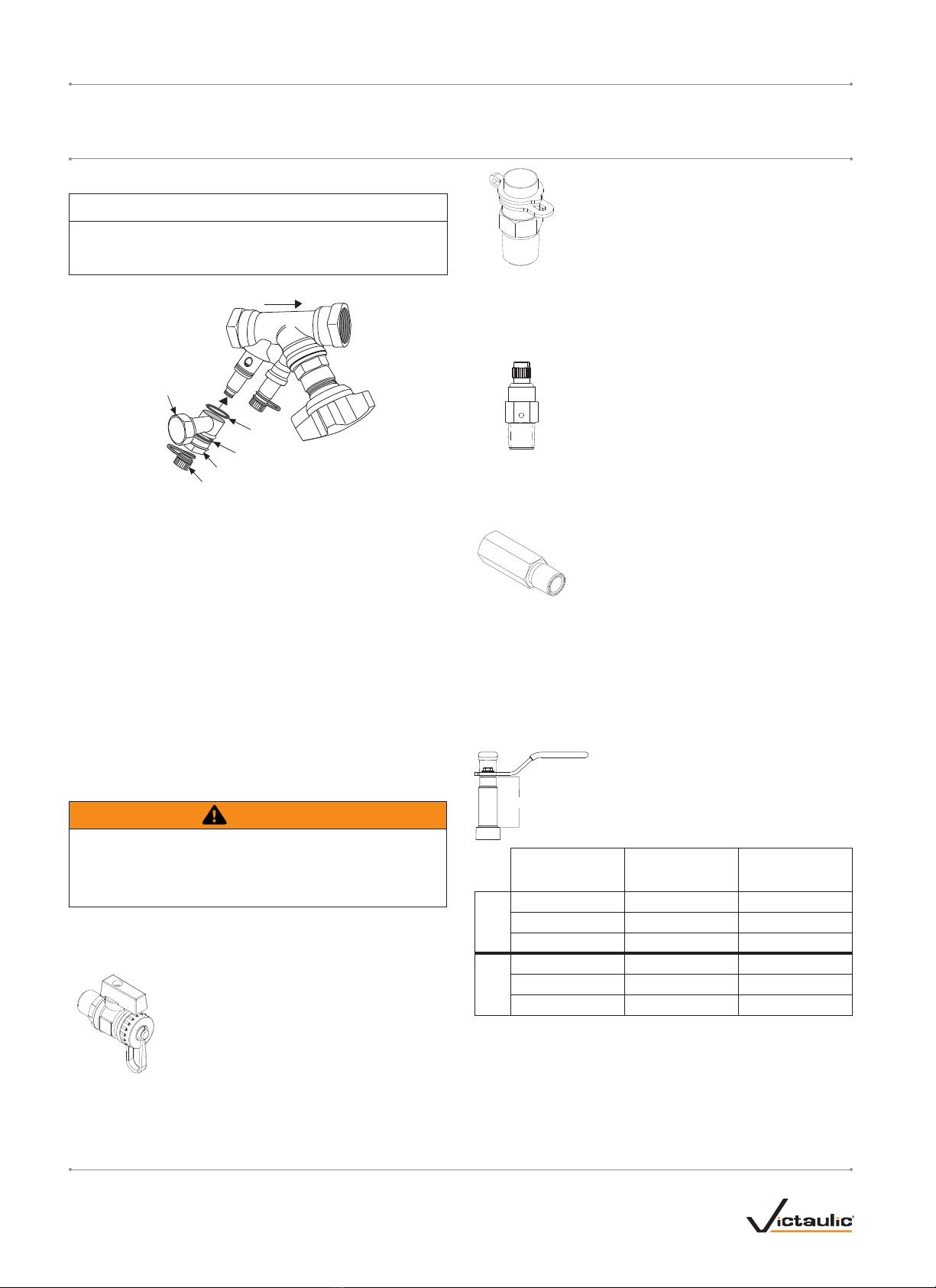
Handle Extension for Series 78Y Strainer/Ball
Valve Combination or Series 78T Ball Valve
Valve Inlet Size
inches
Part Code for
2-inch/51-mm
Handle Extension
Part Code for
4-inch/102-mm
Handle Extension
78Y
½ - 1 P-004-78Y-2HL P-004-78Y-4HL
1 ¼ - 1 ½ P-012-78Y-2HL P-012-78Y- 4HL
2P-020-78Y-2HL P-020-78Y-4HL
78T
½ - ¾ P-004-78Y-2HL P-004-78Y-4HL
1 - 1 ½ P-012-78Y-2HL P-012-78Y- 4HL
2P-020-78Y-2HL P-020-78Y-4HL
In applications where KOIL-KIT™Coil Pack components will be
insulated, the handle extension is available to extend the handle of the
Series 78Y or Series 78T valves to provide clearance for 2 inches/51
mm or 4 inches/102 mm of insulation. Remove the hex washer-head
screw from the handle assembly. Remove the handle assembly and
install the handle extension. Re-install the handle assembly onto
the handle extension by using the hex washer-head screw. NOTE:
Depending on the configuration ordered, some KOIL-KIT™Coil Packs
may be supplied with this option factory-installed.
Handle Extension