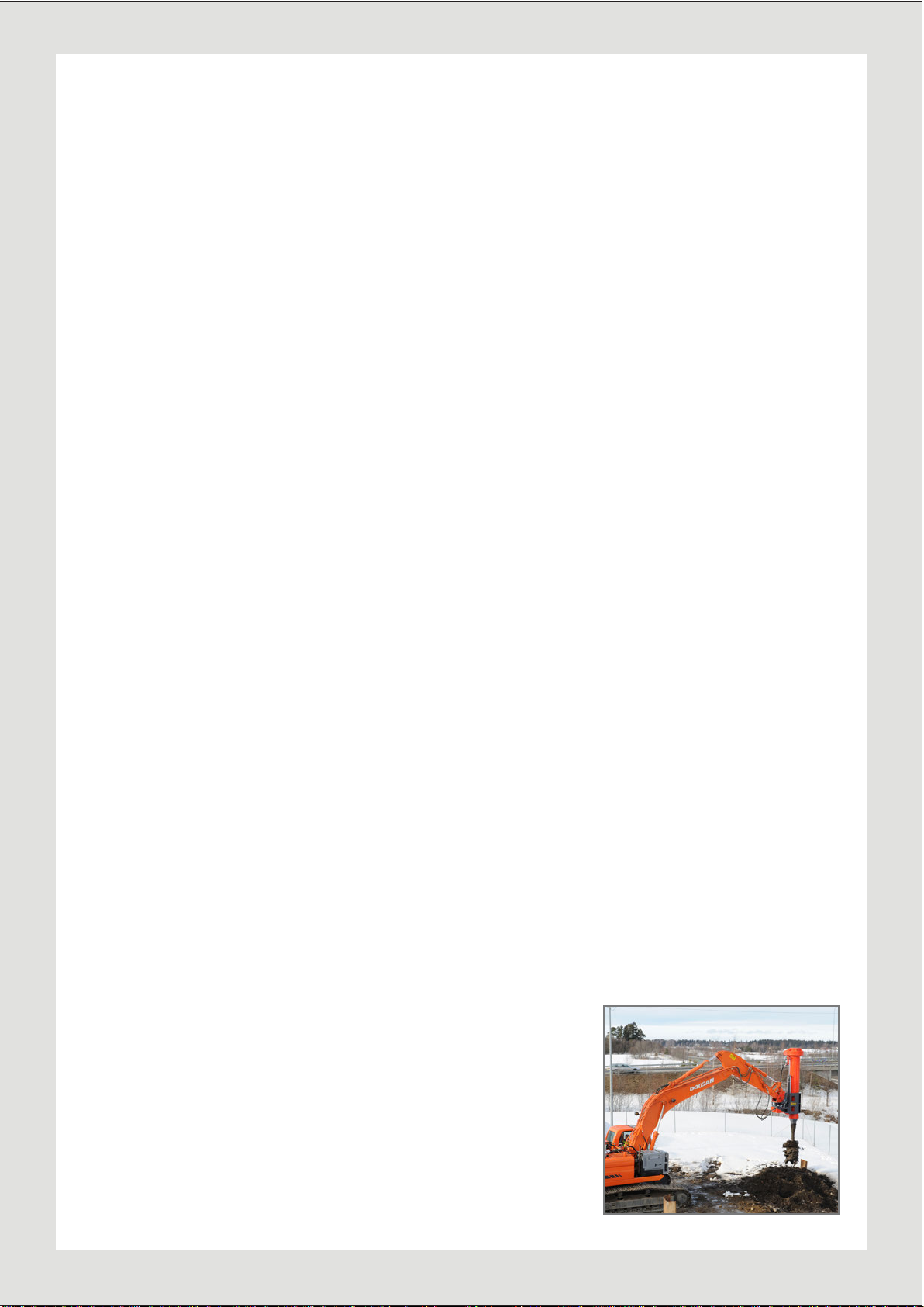
Movax TAD30-2 User manual

Master
page b
Movax Oy
Tölkkimäentie 10
13130 Hämeenlinna
FINLAND
www.movax.com
marketing@movax.
User manual
from SN 1080 onwards
v1.0 2.12.2015
Soil Drill
TAD30-2


Master
page b
INDEX
1. INTRODUCTION .....................................................................................................................
2. SAFETYAND WARRANTY ...................................................................................................
2.1 SAFETY ......................................................................................................................
2.2 WARRANTY CONDITIONS .....................................................................................
3. MOVAX TAD30-2 ....................................................................................................................
4. USING MOVAX TAD – SOIL DRILL .....................................................................................
4.1 ATTACHING THE SOIL DRILL TO THE EXCAVATOR .........................................
4.2 FUNCTIONS ...............................................................................................................
4.3 CONNECTING AUGER TO KELLY BAR ................................................................
4.4 POSITIONING FOR DRILLING ...............................................................................
4.5 DRILLING ..................................................................................................................
5. MAINTENANCE ......................................................................................................................
5.1 LUBRICANTS FOR TAD30-2 ...................................................................................
5.2 DAILY MAINTENANCE ...........................................................................................
5.3 WEEKLY MAINTENANCE .......................................................................................
5.4 MONTHLY MAINTENANCE ...................................................................................
5.5 PIN ASSIGNMENT ON THE VALVE BLOCK (Manual, AutoC) ..........................
5.6 JOYSTICK .................................................................................................................
APPENDIX
1. GENERAL WARRANTY CONDITIONS
2. USED AUGERS
4
5
5
5
6
7
7
8
9
10
11
12
12
12
13
13
15
17
5.5 PIN ASSIGNMENT ON THE VALVE BLOCK (MCS Pro / Lite) ............................ 16

Master
page
1. INTRODUCTION
Movax TAD is a telescopic soil drill that can be
mounted on a standard excavator. TAD does not
require changes on a mechanical structure of the
excavator but can be used as attachment.
Read this instruction manual trough to get under-
standing of safe and allowed use of TAD soil drill.
This manual helps user to get started on site as well
as explains regular maintenance procedures.
Manual includes instructions of control buttons that
an operator use to control hydraulic functions on the
soil drill. This manual does not cover Movax auto
control system. Read separate Auto Steering manual
if your excavator is equipped with this system.
For spare parts there is separate manual `Spare Parts
Book`. Spare part ID number must be mentioned
when placing order. Also, remember to inform the
serial number, type and all the possible changes that
have been done on your Movax TAD. This insures
you will receive the correct spare parts.
Only an operator trained by a Movax manufacturer
or distributor is allowed to operate the soil drill.
Trained operators will receive the operator’s certi-
cate. This is also a condition of warranty.
INTRODUCTION
4
Master
page b
SAFETYAND WARRANTY
1. Movax operator must
be having an operator’s
certicate.
2. The soil drill has to
be connected to excava-
tor according to instruc-
tions. Note requirements
for hydraulic system of the
excavator and connections.
3. Maintenance has to be
performed according to the
instructions given in this
manual or Movax service
personnel.
4. Pressure relief valves
on a valve block on the soil
drill must not be set over
allowed maximum. Failing
to follow this may lead to
break down of telescope
lifting gear. Maximum
pressures are shown on a
hydraulic scheme on spare
part manual.
5. The soil drill should
be only used for soil drill-
ing purposes according to
instructions on this manual.
◊ Operator must be
trained for TAD soil drill
◊ Ensure there are no per-
sonnel in working area
◊ Obey safety instruc-
tions for excavator
◊ Check a connection
between the excavator and
the soil drill regularly and
always before use.
◊ Note stability and lift-
ing capability of the exca-
vator. It is recommendable
to avoid working sideways
to tracks.
◊ Avoid moving a boom
and an arm of the exca-
vator to positions where
accidental movement of
the excavator may cause
collision between soil drill
and cabin. Tilt the soil drill
away from cabin when lift-
ing it up or lowering down.
◊ Beware of drilled
bores in a ground. Bore is
weakening the surround-
ing ground and there is a
risk of falling into it. Never
leave open bores without
proper covering or isolat-
ing.
◊ Beware of over head
electric cables.
◊ Always check for
underground cables, pipes
and other structures before
drilling.
◊ Do not use the tel-
escope of the soil drill for
lifting.
◊ Lower the soil drill to
the ground before leaving
the cabin.
◊ Support and tie the soil
drill properly when loading
and transporting without
the excavator.
◊ Do not go under dril
when it is lifted.
◊ Beware that telescope
can slowly lower down
itself.
SAFETYAND WARRANTY
2.2 WARRANTY SAFETY
2.1 2.1 SAFETY
See general warranty condi-
tions for Movax products
(Appendix 1)
5

Master
page
3. MOVAX TAD30-2
MOVAX TAD30-2
Elevator
Telescope
Elevator
cylinder
Hydraulic
block
Rotation
motors
6

Master
page b
4. USING MOVAX TAD – SOIL DRILL
Before use read this users manual trough and ensure
you have comprehensive knowledge of its functions.
4.1 ATTACHING THE SOIL DRILL TO THE EX-
CAVATOR
Movax soil drill can be mounted on the excavator
with suitable quick hitch or with pins. For safety
reasons make sure that locking mechanism on the
quick hitch full lls the standards and is in good
working condition.
For the hydraulic functions the soil drill needs to be
connected to one way auxiliary circuit of the exca-
vator. In addition to this there is a need for drain-
age line that is connected directly to hydraulic tank
of the excavator. Minimum sizes of the piping are
shown in a table below.
Connect the drainage and the return lines before
connecting the pressure line. Ensure that all ball
valves on the excavator pipes are open if installed.
Hydraulic motors will be damaged if the lines are
not connected properly prior the use of the soil drill.
Also, keep all connectors clean and use protector
caps when not connected.
Then connect an electric cable that is needed to
control the functions of the drill. Electric connector
must also kept clean and dry for problem free opera-
tion.
HYDRAULIC REQUIREMENTS FOR TAD-30S
Pressure pipe / hose ø 30 mm / 1”
Return pipe / hose ø 30 mm / 1” or
42 mm / 1 ¼”
Drainage pipe / hose ø 7 mm / ⅜”
Oil ow, minimum* 75 l/min
Oil ow, maximum* 250 l/min
Relief setting 320 BAR
Return pressure, maxi-
mum 5 BAR
*Auger RPM is depending on the oil ow.
TAD30-2 11 – 74 1/min
USING MOVAX TAD – SOIL DRILL
7

Master
page
4.2 FUNCTIONS
Rotation. The auger is rotated by two axial piston
motors. TAD-30s has two different speeds for rota-
tion. Higher speed employs only one of the motors
with maximum torque of 15.000 Nm. Lower speed
mode engages both motors and delivers 30.000 Nm
of torque.
Lowering and raising the auger. Telescope and el-
evator mechanisms are used for lowering and raising
the auger during drilling. Keep the auger paralled
and centered to the bore at all times. Careless mov-
ing the boom or the arm may cause bending forces
to the telescope lead to break downs.
Movax TAD30-2 soil drill has telescopic kelly bar
with two moving extensions. Movement is imple-
mented with a hydraulic cylinder. The mechanism is
working two ways thus enabling the hydraulic push
and pull. During the drilling work the kelly bar can
be also released to oating mode.
Elevator refers to a lift mechanism on between main
body and a part that links the soil drill to the exca-
vator. Elevator is moving the drill up and down by
hydraulic cylinders. This can be used for reaching
the maximum depth but also for drilling or pulling
out at any depth as it creates same direction linear
movement as the telescope.
Side tilt. The soil drill tilts 30º both side ways. This
movement works with two hydraulic cylinders. The
tilt is used to straighten the drill when the excavator
is on slope or uneven surface. Tilt can be also used
for raked drilling.
USING MOVAX TAD – SOIL DRILL
8

Master
page b
4.3 CONNECTING AUGER TO KELLY BAR
The auger is mounted into the telescopic kelly
bar with bolt-on adapter that is changeable for
different size and shape bars. This enables the use
of the augers with different connection standard.
Ask you Movax dealer for needed type adapter.
Following procedure is easy and safe way for
mounting the auger. Pay attention to safety, never
go between moving parts.
1. Make sure the adapter is rmly bolted to the
telescope kelly.
2. Lay the auger on the ground and support the
end against solid rest, track of the excavator in
example.
3. Line up the soil drill and the auger.
4. Rotate the auger or the telescope until the kelly
bar and the box are in same position. Note the
position of the locking pin and hole.
5. Use telescope to push the kelly bar into the
auger.
6. Install the locking pin(s).
USING MOVAX TAD – SOIL DRILL
9
Master
page
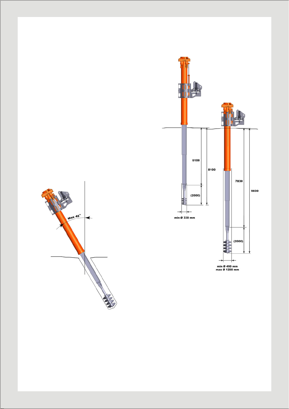
4.4 POSITIONING FOR DRILLING
Lift the soil drill upright position and move to
wanted location of drilling. The telescope is ide-
ally in a shortest position at the beginning and
the elevator roughly halfway or lover position.
Then use the boom of the excavator to position
the end of the auger about half metre above the
ground. Alignment can be done by moving the
arm, the bucket cylinder of the excavator and tilt
function on the soil drill.
Movax soil drill can be used also for raked piles.
Drilling angle must not exeed 45 degrees thus
drilling on horizontal position is not allowed.
Rotation of the telescope in too big inclination
can cause a damage to the mechanism used to
drive the telescope.
Working range measured to the end of the
telescope and with 2000 mm long auger.
USING MOVAX TAD – SOIL DRILL
10

Master
page b
4.5 DRILLING
Begin the drilling by starting the rotation clockwise.
Rotation speed can be set by changing the oil ow
from the excavator. This is easily done by chang-
ing the running speed of a diesel engine. TAD-30s
enables two different speeds by running one or two
motor at the time. Higher speed is in use by using
one motor and lower speed with higher torque when
running both motors. It is recommendable to start
with one motor and switch to two when more torque
is needed.
Rotating auger can be now lowered to the ground by
utilising the telescope. There are two ways of op-
erating telescope. It can be released to go down by
the gravity and a force created by the auger ights.
Other option is to push the kelly out hydraulically
and that way put more down force in a case that au-
ger is not cutting well into soil by its own weight.
The auger should be driven into the soil from 0.2 to
0.8 metres at time depending on the ground condi-
tion, size of the auger as well as the type of the
auger. Then stop the rotation and rotate some half
round counter clock wise to get the auger loose
from the cutting point. This may not be needed with
granular and very light soils. Pull the telescope in
until whole length of the auger is above the ground.
In addition to telescope movement the elevator can
be used to lift the auger up. In order to avoid bend-
ing the telescope tubes be cautious when moving
the boom, arm or bucket cylinder whilst the auger is
lovered into the ground or casing.
Remove the soil from the auger by rotating it coun-
ter clock wise.
USING MOVAX TAD – SOIL DRILL
11

Master
page
5. MAINTENANCE
5.1 LUBRICANTS FOR TAD-30
1. Lubricant for greasing points; grease
nipples, rotary gear, slide bearings and all
slides on the telescope and the elevator:
Open gear grease, greasing intervals on
chapters below.
2. Lubricant for planetary gears: 80W-90
API GL-5 gear oil. First change after 40
hours, then every 6 months or 250 hours.
5.2 DAILY MAINTENANCE
Check daily:
1. Hydraulic hoses and connections, pay
attention to possible damages, leakage and
loose fastening
2. Oil level of the planetary gear
3. The bolts on kelly bar end - check the
torque and tighten if needed
4. Slides on the elevator frame
5. Mechanical connection to the excavator
and the bolts connecting the adapter to the
drill
6. Tilt pin and fasteing of the tilt cyliders
Note. Do not operate the drill if any of the
mechanical or hydraulic components is
damaged or loose.
Grease daily:
1. Slide bearing in lower end of a frame
tube.
2. Slides on the elevator.
3. Telescopic kelly bar (may not be neces-
sary on daily basis).
Note 1. Continuous rotation of the drill is
not allowed while greasing the telescope
with the drill in horizontal position. The
rotation can be still used shortly to spin the
telescope around for better access for greas-
ing.
Note 2. Do not rotate when top cover is
open. There is a risk for hose failure.
MAINTENANCE
12

Master
page b
5.3 MAINTENANCE WEEKLY OR EVERY
40 HOURS
Check weekly:
1. Open the top cover and inspect the gear
wheels, clean if needed.
2. Inspect a rotary joint. Make sure there are
no leakages and check that the rotary joint
cannot turn around but a stopper is rmly
xed.
3. All points mentioned in a chapter DAILY
MAINTENANCE
4. Retract telescope, after that two grease
nipples comes visible (marked “A” in photo)
Grease weekly:
1. Gear wheels inside the top cover
2. Bearing of the rotary gear
3. Tilt pin and cylinder bearings.
4. Retract telescope, after that two grease
nipples comes visible (marked “A” in photo)
5.4 MONTHLY MAINTENANCE
1. Clean the gear wheel casing and telescope.
1.1. Open the top cover and remove the adapter
for the auger from the telescopic kelly bar
1.2. Clean the gear wheel casing and telescopic
kelly bar both inside and outside. Use high
pressure cleaner with hot water if available.
2. Inspect all related parts
3. Use new bolts for kelly bar adapter
4. Shim or change the slides on the elevator if
necessary
5. Inspect and lubricate all points mentioned in
the chapters DAILY -AND WEEKLY MAIN-
TENANCE.
MAINTENANCE
A
A
13
Master
page
6. Check the chain adjustment in the telescope.
6.1 Pull mechanically the telescope fully in to the
shortest length. You can ensure fully in position
with hand winch.
6.2 Tighten the nuts using special tool. Right mo-
ment is achieved by hand tightening when using
this tool. This way right tightness of retraction
chains is ensured.
MAINTENANCE
6.3 Under top cover can be found two springs
(marked “B” in photo). These springs must have 7
mm compression from free length to ensure right
tightness on extension chains.
B
B
14
Master
page
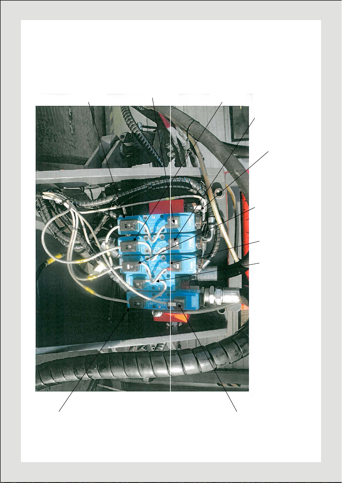
MAINTENANCE
s
Telescope up
Cable No.7
Telescope down Elevator down
Cable No.8 Cable No.6
Elevator up
Cable No.5
Rotation reverse
Motor 1
Cable No.2
Rotation forward
Motor 1
Cable No.9
Motor 2
Cable No.1
Tilt right
Cable No.3
Tilt left
Cable No.4
Auger
float
Cable No.10
Activation of
5.5 PIN ASSIGNMENT ON THE VALVE BLOCK0DQXDORU$XWR&FRQWUROV\VWHP
15

10
&DEOH
95/6
3/4
1/2
7/8
5.6 PIN ASSIGNMENT ON THE VALVE BLOCK AU-02-0-4 FOR MCS PRO AND MCS
LITE CONTROL SYSTEMS (CABLE 40438)
Wire No. Function
1 Elevator up
2 Elevator down
3 Tilt right
4 Tilt left
5 Rotation reverse motor 1
6 Rotation forward motor 1
7 Telescope up
8 Telescope down
9 Activation of motor 2
10 Auger oat
16
Master
page b
- 9 -
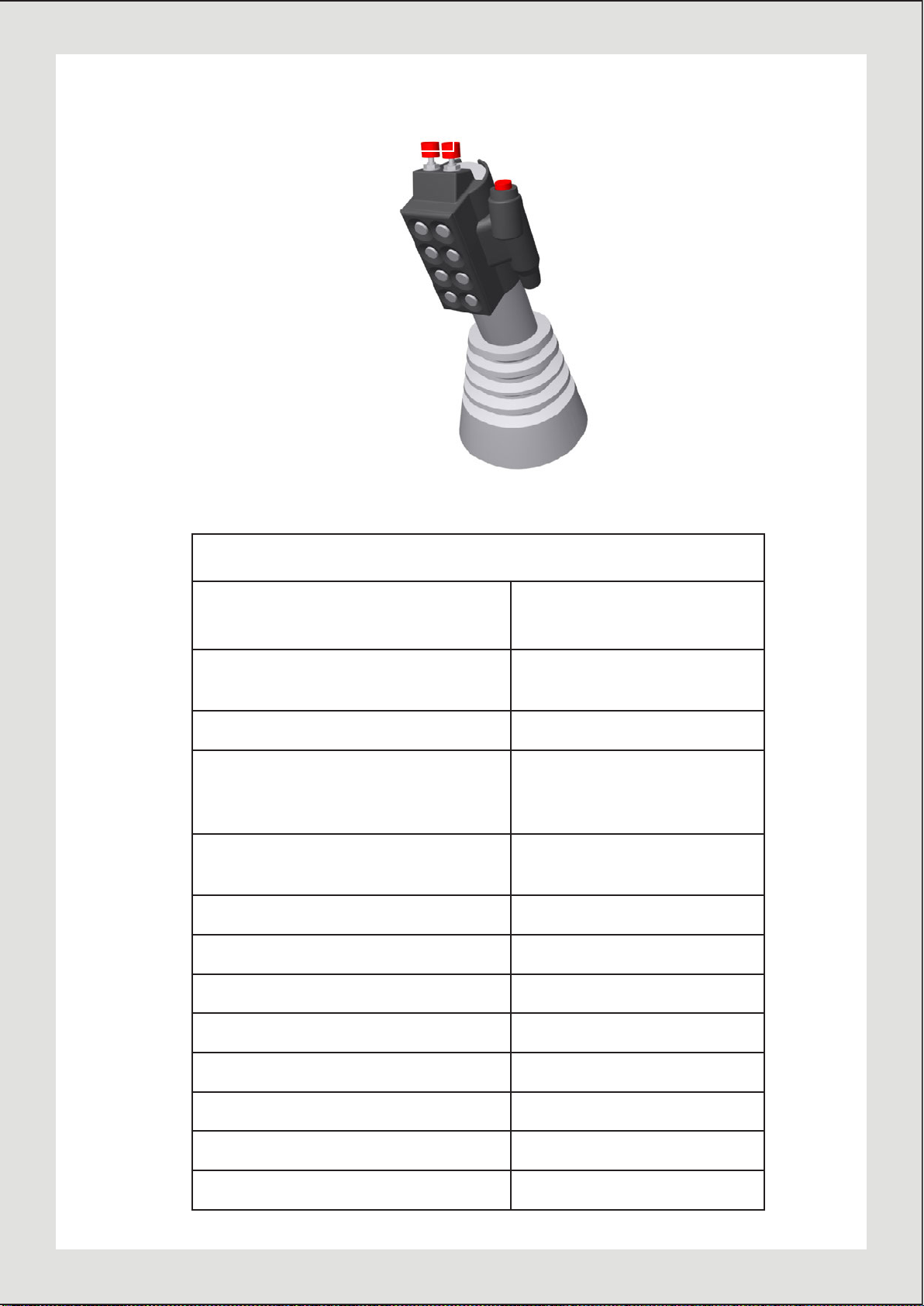
FUNCTION
TAD-30S
BUTTON OR
COMBINATION
Auger rotation reverse 1
High torque / low speed 2
Kelly up 3
Kelly down 4
Elevator up 5
Elevator down 6
Tilt left 7
Tilt right 8
Auger rotation / drilling clockwise
9
Kelly float on / off 9 + click 2
Joystick
65
9
1 2
3 4
7 8
10 11
TAD-30
FUNCTION BUTTON OR
COMBINATION
Auger rotation fast forward
Motor 1 9
Auger rotation fast reverse 1
Auger rotation forward
High torque (low speed)
Motor 1 and 2 9 + 2
Auger rotation reverse
(low speed) 1 + 2
Tilt right 3
Tilt left 4
Elevator up 5 + 11
Elevator down 6
Telescope up 7
Telescope down 8
Kelly oat on / off 9 + click 2
Drill straightening, automatic 9 + 11
5.JOYSTICK
17

! " # $ % # & ' # ( ) ' * + , , # ' $ % , # ' ' %
& ' , & ) # % + ' & # + ) , ) # , % # % , % ' ) ' %
+ ' # ' % , ' -
. / ) '
* ' # ' % . + % * ' # % %
! " # % # & ' #
( ) ' * + , ) % + # & ' ' % , % ' # # + # , ) % + % , ' #
( ) ' * +
! " # 0 % * % ' % ' % & & # ( ) ' * + % $ #
1 # # ' ' & * % % * '
# % , * % % % * * % ' $ # % , &
# 2 ' $ * % % + ' , * % &
3 , # ' ' % * '
' % & ' # 4
5 # + $ , , ) % ' + & * ' $ , # ' ' %
65 , ) % + % & & # ' % ) , ' % $ ' 6
! " # ' % * % ' $ # ' $
* ' 7 ' % & & ' # + ' , * # ) , %
, 5 % * * % ) % # ' * ' # 2 + ' , * # ) , % 6 * * # 6
! " #
# 5 , ) % + ' ' %
! " # # + $ % % % * % % ' 6&
5 , ) % + + 8 % , & ' + # ' & & % ) + , , # ' $ &
- & ' + ' ' %
# % , 4
5 9 + & ' $ ' $ * % : % % 7 % & % 7 , 5
65 ; # + $ % , , ) # * # ) , % 6 * # $ ' % ' % ) , ' % $ ' 6
! " # $ ' % ' % ) , ' % ' ' % ) , ' + ) & # & ' # ' * # ) ,
, 5 ; # + $ % , , ) # ) % ' $ % * * % + ) , ) # * * # 6
!
" #
# 5 ; # + $ % , , ) # 6 , ) % * ' + ' , 8 + # $ ' % ' % ) , ' %
$ ' 6
! " # ' % * % ' %
5 ; # ' , ' # ' , , % % 6)$ 6 # + $ # * # ) , %
APPENDIX 1
18
< ; # # ' ' & , # ' ' %
, ) % + + ) % % # # + $ # * # ) , # + $ # *
! " # ' % * % 7 '
( ) ' # 6
! " #
! " # % ' $ , $ % , # + $ , , # ' $ ' % , ' * ' , & ' % 7 ' '
' % & # ' % , # # + $ * # 6 , ) % + ' % , # 6
! " # # , ) % + $ % * & + % # & ' * '
; # ' % $ + & # % , # ' ' % ' & & * ' + ' & 6 % & # ) $ $ ' ' %
6 * ' % = # ' % * ) ' % % & # 6 $ ' ' % 7 # ' % * ) , 6 % & # '
> ?
+ & ' # ' % ' , , ) ' ' ' # 6 ' *
> ?
+ & ' 7 1 - . @ @ A
19

Please return completed warranty card to Movax Oy Ltd by email to m[email protected] or
by fax to +358 (0)3 616 1641or by mail to Tölkkimäentie 10, FI-13130 Hämeenlinna, Finland.
Warranty card can also be filled at www.movax.com.
WARRANTY CARD
Model
Serial number
Movax Oy Ltd grants a warranty to the delivered new equipment according to Movax warranty conditions. The
warranty period is 12 months and the warranty period starts when Movax Oy Ltd has delivered the equipment to
the customer. The delivery is considered made when the customer has received the equipment or Movax Oy Ltd’s
representative has installed the equipment as agreed. The warranty card is required for warranty coverage and it
helps in case of any warranty issues.
DISTRIBUTOR / DEALER (seller)
Company name:
Contact person:
CUSTOMER
Company name:
Contact person:
Address:
Phone:
Email:
MOVAX PRODUCT
Model:
Serial number:
Installation date:
Installation made by:
Additional information:
20
Table of contents


