Movies 2 go MM1504 User manual

Installation Guide
MM1504
15.4" ROOF-MOUNTED
TFT-LCD
VIDEO MONITOR
Installation Guide

2
Important Notice
An LCD panel and/or video monitor may be installed in a motor vehicle and visible to the
driver if the LCD panel or video monitor is used for vehicle information, system control,
rear or side observation or navigation. If the LCD panel or video monitor is used for
television reception, video or DVD play, the LCD panel or video monitor must be installed
so that these features will only function when the vehicle is in “park” or when the vehicle’s
parking brake is applied.
An LCD panel or video monitor used for television reception, video or DVD play that
operates when the vehicle is in gear or when the parking brake is not applied must be
installed to the rear of the driver’s seat where it will not be visible, directly or indirectly, to
the operator of the motor vehicle.
Licensed under one or more of the following patents,
Patent NOS. 5,775,762 and 5,927,784

3
MATERIALS INCLUDED IN THIS PACKAGE:
1) MM1504 TFT-LCD Monitor (P/N 136-4466) (1 pc)
2) Power Cable (P/N112-3845) (1 pc)
3) Remote Control (P/N 136-4457) (1pc)
4) Hardware Package:
• M4.2 x 16mm Phillips Self Tapping STPan Head Washer Screws (10 pcs)
• M4 x 8mm Phillips ST Pan Head Screws (8 pcs)
5) Mounting Bracket (P/N 108-3964) (1pc)
6) Trim Ring (P/N 102-4418) (1pc)
TOOLS REQUIRED:
#2 Phillips Screwdriver
#1 Phillips Screwdriver
Utility or Razor Knife or Shears
Wire Strippers
Upholstery hook tool (for removal of panels as necessary)
Electrical Tape
MaskingTape
Multimeter (to verify 12 volt DC and continuity: Do not use a test light or logic probe)
Marker pen – to mark headliner
Scribe (to mark trim ring if used)
Misc. electrical connectors (to connect to vehicle power source). Requirements will vary from vehicle to
vehicle.
Parts Name Quantity
TFT-LCD Display MM1504 1
IR Remote Control w/Battery 1
Car Power Cable 1
Metal Mounting Plate 1
ST4.2x16 Screw 10
CM 4x8 Screw 8
Adhesive foam 8
User's Manual 1

4
GENERAL INSTALLATION APPROACH:
1) Decide upon system configuration and options that will be installed (i.e.: what components, RF Modu-
lator/external amp, remote headphones, DVD, etc.).
2) Review all manuals to become familiar with electrical requirements and hook ups.
3) Decide upon mounting locations of all components and method of mounting.
4) Prep the vehicle by removing any interior trim necessary to gain access to vehicle's wiring as well as
all areas where interconnecting wire harnesses will need to be located. If any access holes need to
be cut into the vehicle (headliner, other trim components etc.), this should be done now as well.
5) Route the wiring harnesses throughout the vehicle as necessary. (Refer to the Wiring Diagrams in
this manual as well as the wiring instructions for the individual components and accessory options
being installed). Be sure that all wiring is protected from sharp edges and is routed in such a manner
that it will not be pinched when all components and interior trim are fully installed. Be sure to leave
enough slack in the wiring at each component to allow working room.
6) Remove allA/V system components from their packaging and place them loosely in the vehicle at their
respective locations.
7) Connect all components together (electrically) and verify proper operation of all system functions.
Note: This is best done BEFORE components have been permanently mounted.
8) After verifying proper operation of the system, proceed to mount each of the components.
9) When all components are mounted, recheck function of entire system again to ensure that no wiring
was pinched or connected improperly during final installation.

5
VEHICLE PREPARATION:
1) Locate a Battery and accessory power source (+12v when key is in theACC. and run positions, and
0v when key is off).Also find a location that will provide a good grounding point. Generally, this wire
can be found at the ignition switch or fuse-box.
2) The mounting method and location will vary from vehicle to vehicle, so this manual will only focus on
the installation of the video monitor and related accessories.
3) Generally, the best location for the video monitor is where the vehicle's factory dome light is installed.
The monitor should be located in such a manner that it can be comfortably viewed by rear seat
passengers. NEVER INSTALLTHE MONITOR INAPLACE WITHIN THE DRIVER'S VIEW. THIS IS
NOT ONLY DANGEROUS, BUT IT ISALSO ILLEGAL.
4) Once the mounting location of the monitor has been determined, there may be additional preparation
work necessary, depending on the vehicle structure and installation method. Some of the steps that
may be required are:
a) Removal of the vehicle's dome light
b) The headliner may need to be trimmed
6
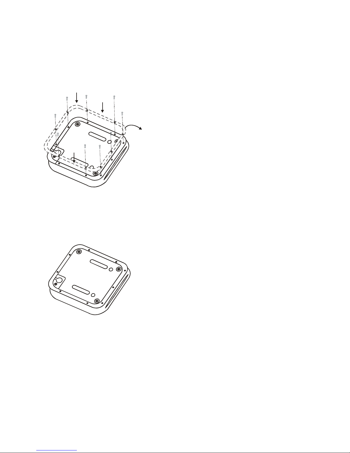
TRIM RING INSTALLATION:
1) The trim ring is attached to the video monitor
using the perimeter screw bosses. It is important
that the screws used in this installation are not
overtightened, and that the video monitor and trim
ring are mounted in such a way that the assem-
bly does not distort (or bend) when the mounting
screws are tightened. The trim ring MUST be
screwed to the unit. (Refer figure 1.)
Figure 2
Trim Ring
Figure 3
2) The MM1504 is now ready to be mounted in the
vehicle. (Refer figure 2.)
Figure 1
Figure 2
7
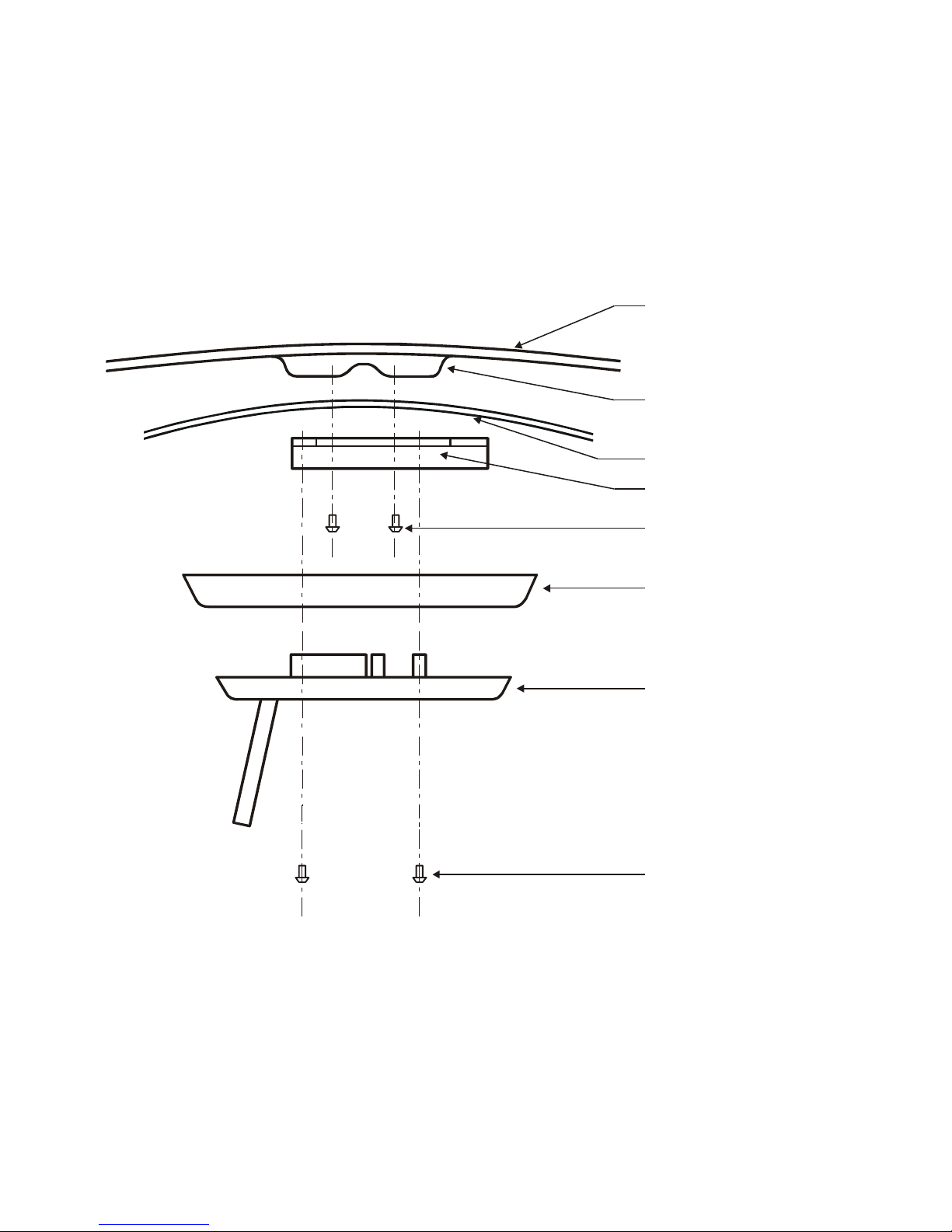
MOUNTING THE TRIM RING
Roof
RoofSupport
Headliner
Mounting Bracket
(4) Self-Tapping Screws
(not supplied)
Trim Ring
Video Unit
(5) #8 Flat Washers
(5) # 8x3/4?Self-Tapping
Screws
8 CM 4x8 Screws
8
* Fuse all power leads at the vehicle's power source.

9
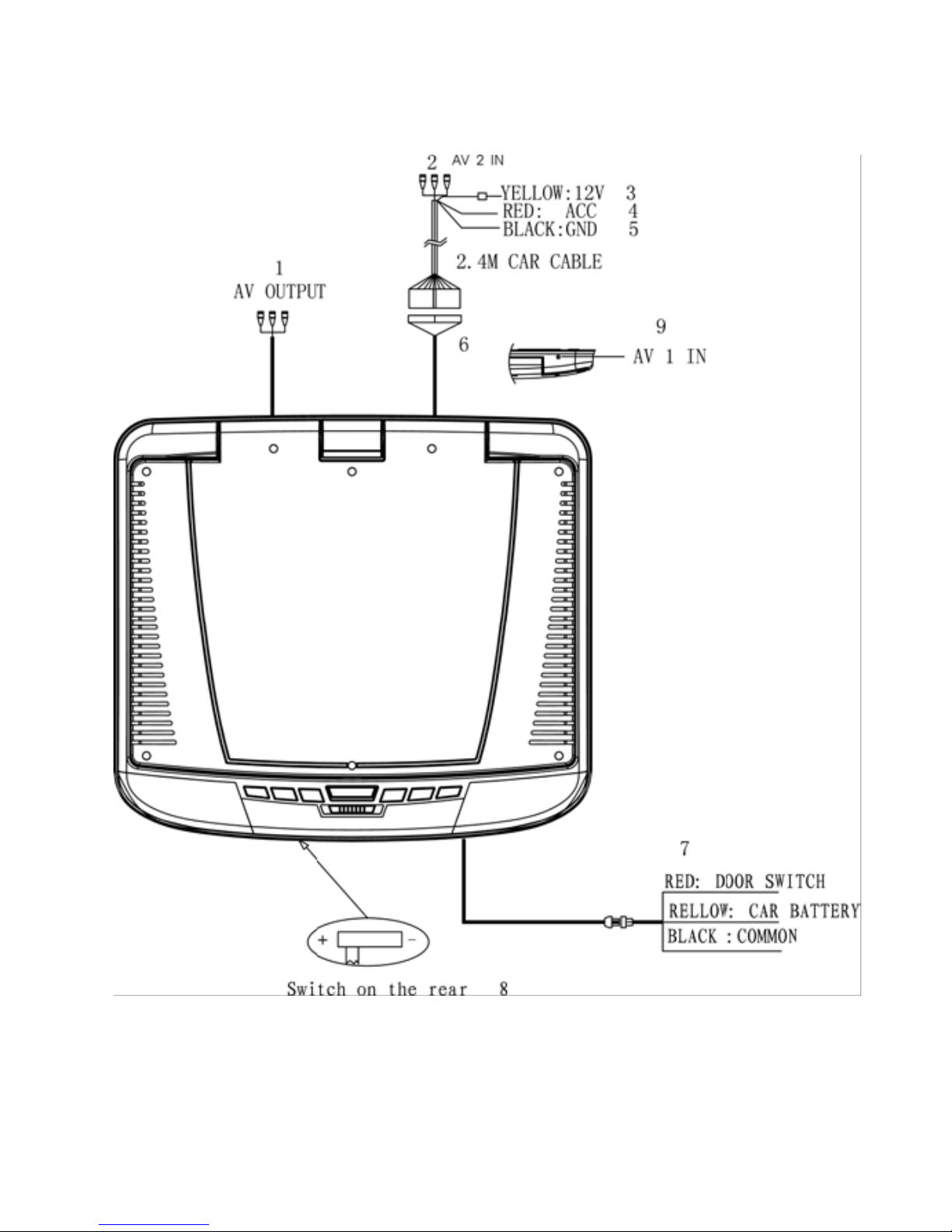
MM1504 MONITOR WIRING
1. AUX A/V, Output
An auxiliary A/V output is provided to drive an external monitor.
2. AUX 1/AUX 2 A/V Inputs
RCA Jacks: Can be connected to an external source.
3. Battery + Lead (Yellow)*
Connect to the positive terminal of the car battery.
4. ACC Power Lead (Red)*
Connect to ACC power, powered when ignition key position is in ACC or run position.
5. Ground Lead (Black)
Connect the lead to a good chassis ground on the car. Make sure the connection is made to bare
metal and is securely fastened using the sheet metal screw provided.
6. Connector
This is connected to the Overhead Monitor through the 2.4m, Mini-DIN Extension Cable.
7. Dome Light Wire
This wire connects the built-in dome light to the cable from the car's dome light switch.
8. Polarity Switch
Slide to "-" at the left position if your vehicle's power supply system is negative; slide to "+" at the
right position if your vehicle's power supply system is positive. The default polarity is negative.
9. AV 1 IN
Notes: 1. Position slide switch fully to the left or right limit.
2. Do not activate this switch after installing the player. Otherwise, the player will be
damaged.
10
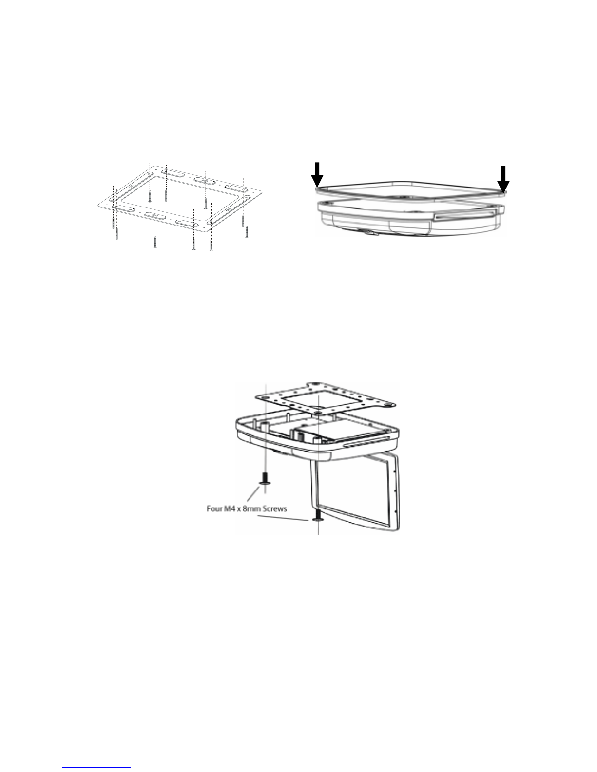
Monitor Installation
To install the monitor:
1. Disconnect the negative terminal of the battery.
2. Disconnect the original dome light.
3. Attach the metal mounting plate to the roof bow using the 10 ST 4.2 16mm screws and washers.
Use care to avoid damaging the vehicle roof.
4. Pull out the original dome light Power wire and Signal/Power Cable through the original dome
light opening.
5. Connect the input and output cables.
6. Connect the wire harness in the following order: ground wire, battery wire, ACC wire, and door
wire.
7. Attach the monitor to the metal mounting plate using 4 M4x8mm screws.
8. Reconnect the ground terminal of the battery.
Notes:nConnect the red wire to the ACC of the ignition switch, or else the battery charge might
be drained off prematurely.
nIf a fuse is open, first make sure that the cables have not caused a short circuit, and then
replace the old fuse with a new one of the same rating.
nDo not have unconnected cables or terminals touch the metal on the car or any other
conducting material.
nTo prevent short circuits, do not remove the caps from unused terminals or from the
ends of the unconnected cables.
nAfter the display unit is installed, check and make sure the brake lights, blinkers, wiper,
etc., on the vehicle are working properly.
nInsulate unconnected wires with vinyl tape or other similar material.

11
TROUBLESHOOTING
SYMPTOM: REMEDY:
No power at Video Monitor -Verify +12 VDC on Red wire at Yellow wire Power Harness be
hind video monitor. Verify ground con-
nection with continuity test from known good ground to
black wire at Power Harness
Power but no video or sound -Verify that the correct source is selected (DVD, AV 1 or AV 2).
Verify that the source is on and play-
ing known good media. Verify connections at both ends of
the source component harness.
Picture, but no sound -Verify that the headphones are turned on; check headphone
batteries . Verify that power is avail-
able to the FM Modulator; make sure modulator is tuned to
the correct FM station

12
© Copyright 2007 AEC 150 Marcus Blvd. Hauppauge, NY 11788
128-8154
Other manuals for MM1504
1
Table of contents
Other Movies 2 go Monitor manuals


