Mower Land MLTILL5 User manual
MOWER LAND
Before operating this appliance, please ensure that you read & understand all
the instructions that apply to it, as failure to comply wih these instructions
may result in personal injury to other persons, and also increase the risk of
fire. Please ensure that any replacement parts or accessories used with this
appliance are correctly and/or securely fitted before use.
Please retain these instructions for constant reference.
OPERATOR' S MANUAL
MODEL MLTILL5
MOWER AND TILLERL

* Measured according to 2000/14/EC
* Measured according to EN1033:1995
2
2
TABLE OF CONTENTS
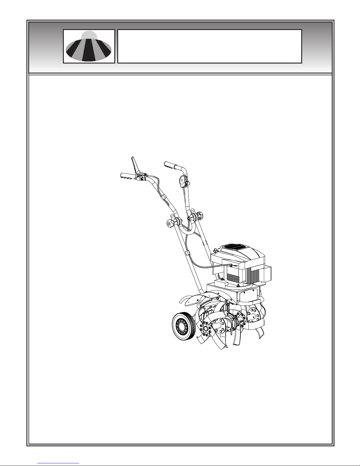
INTRODUCTION
Your new front tine tiller will more than satisfy
your expectations. It has been manufactured under
stringent quality standards to meet superior
performance criteria. You will find your new tiller
easy and safe to operate, and with proper care,
it will give you many years of dependable service.
Carefully read through this entire
operator’s manual before using your
new tiller. Take special care to heed
the cautions and warnings.
Your tiller has many features that will make your
job faster and easier. Safety, performance, and
dependability have been given to top priority in
the development of this machine, making it easy
to maintain and operate.
The Engine Manufacturer is responsible for all
engine-related issues with regards to performance,
power rating, specifications, warranty and service.
Please refer to the Engine Manual, packed
separately with your unit, for more information.
Introduction
Specifications
Symbols
Safety
General Safety Rules
Specific Safety Rules
Contents supplied
Assembly
Know your tiller
Features & Controls
Tiller Operation
Maintenance
Storage
Trouble Shooting
Parts Schedule
2Mowerland Tiller
ENVIRONMENTAL
Recycle unwanted materials instead of
disposing of them as waste. All tools,
hoses and packaging should be resorted,
taken to the local recycling center and
disposed of in an environmentally safe
way.
The rating plate on your machine may show
symbols. These represent important information
about the product or instructions on its use.
SYMBOLS
Specifications
B&S QUANTUM 60
500mm
250mm
120rpm
42.5kg
96 dB(A)
79.3 dB
Left: 4.10 m/s
Right: 3.68 m/s
Engine
Cultivating Width
Cultivating Depth
Tine Speed
Weight
Sound power level
Sound pressure level
Vibrating level on
handlebar grips
2
2
2
3
3
5
6
6
9
9
12
13
14
15
16
Wear eye protection.
Wear hearing protection.
Read these instructions for use carefully.
Wear safety footwear.
Wear safety gloves.
It is forbidden to remove or tamper with
the protection devices and safety devices.
Keep away from rotating tines. Rotating
tines will cause injury.
Do not touch a hot muffler, gear housing
or cylinder.
Do not smoke or have open flames.
Thrown objects.
Keep bystanders away.
EC declaration of conformity 17

SAFETY
Understand your machine
Use safety equipment. Always wear eye protection.
Safety equipment such as a dust mask, hard hat,
or hearing protection used for appropriate
conditions will reduce personal injuries.
General Safety Rules
Read and understand the operator’s manual and
labels affixed to the machine. Learn its application
and limitations as well as the specific potential
hazards peculiar to it.
Be thoroughly familiar with the controls and their
proper operation. Know how to stop the machine
and disengage the controls quickly.
Make sure to read and understand all the
instructions and safety precautions as outlined in
the Engine Manual, packed separately with your
unit. Do not attempt to operate the machine until
you fully understand how to properly operate and
maintain the Engine and how to avoid accidental
injuries and/or property damage.
Work area
Never start or run the engine inside a closed area.
The exhaust fumes are dangerous, containing
carbon monoxide, an odorless and deadly gas.
Operate this unit only in a well ventilated outdoor
area.
Never operate the machine without good visibility
or light.
Never operate the machine on a steep slope.
Personal safety
Do not operate the machine while under the
influence of drugs, alcohol, or any medication that
could affect your ability to use it properly.
Dress properly. Wear heavy long pants, boots and
gloves. Do not wear loose clothing, short pants,
jewelry of any kind. Secure long hair so it is above
shoulder level. Keep your hair, clothing and gloves
away from moving parts. Loose clothes, jewelry
or long hair can be caught in moving parts.
Check your machine before starting it. Keep guards
in place and in working order. Make sure all nuts,
bolts, etc. are securely tightened.
Never operate the machine when it is in need of
repair or is in poor mechanical condition. Replace
damaged, missing or failed parts before using it.
Check for fuel leaks. Keep the machine in safe
working condition.
Never tamper with safety device. Check their
proper operation regularly.
Do not use the machine if the engine’s throttle
control does not turn it on or off. Any gasoline
powered machine that can not be controlled with
the engine throttle control is dangerous and must
be replaced.
Form a habit of checking to see that keys and
adjusting wrenches are removed from machine
area before starting it. A wrench or a key that is
left attached to a rotating part of the machine may
result in personal injury.
Stay alert, watch what you are doing and use
common sense when operating the machine.
Do not overreach. Do not operate the machine
while barefoot or when wearing sandals or similar
lightweight footwear. Wear protective footwear
that will protect your feet and improve your footing
on slippery surfaces. Keep proper footing and
balance at all times. This enables better control of
the machine in unexpected situations.
Avoid accidental starting. Be sure the engine’s
throttle control is off before transporting the
machine or performing any maintenance or service
on the unit. Transporting or performing
maintenance or service on a machine with its
throttle control on invites accidents.
Fuel safety
Fuel is highly flammable, and its vapors can explode
if ignited. Take precautions when using to reduce
the chance of serious personal injury.
When refilling or draining the fuel tank, use an
approved fuel storage container while in a clean,
well-ventilated outdoor area. Do not smoke, or
allow sparks, open flames or other sources of
ignition near the area while adding fuel or operating
the unit. Never fill fuel tank indoors.
Keep grounded conductive objects, such as tools,
away from exposed, live electrical parts and
connections to avoid sparking or arcing. These
events could ignite fumes or vapors.
3
Mowerland Tiller

Service
Keep the engine and muffler free of grass, leaves,
excessive grease or carbon build up to reduce the
chance of a fire hazard.
Keep cutting tools sharp and clean. Properly
maintained cutting tools with sharp cutting edges
are less likely to bind and are easier to control.
Never douse or squirt the unit with water or any
other liquid. Keep handles dry, clean and free from
debris. Clean after each use.
Observe proper disposal laws and regulations for
gas, oil, etc. to protect the environment.
Store idle machine out of the reach of children
and do not allow persons unfamiliar with the
machine or these instructions to operate it. Machine
is dangerous in the hands of untrained users.
Before cleaning, repair, inspecting, or adjusting,
shut off the engine and make certain all moving
parts have stopped. Always make sure the engine’s
throttle control is in its “STOP” position. Disconnect
the spark plug wire, and keep the wire away from
the plug to prevent accidental starting.
Have your machine serviced by a qualified repair
personnel using only identical replacement parts.
This will ensure that the safety of the machine
maintained.
Never store fuel or machine with fuel in the tank
inside a building where fumes may reach an spark,
open flame, or any other source of ignition, such
as a water heater, furnace, clothes dryer and the
like. Allow the engine to cool before storing in any
enclosure.
Always stop the engine and allow it to cool before
filling the fuel tank. Never remove the cap of the
fuel tank or add fuel while the engine is running
or when the engine is hot. Do not operate the
machine with known leaks in the fuel system.
Loose the fuel tank cap slowly to relieve any
pressure in the tank.
Never over fill fuel tank. Fill tank to no more than
12.5mm (1/2”) below the bottom of the filler neck
to provide space for expansion as the heat of the
engine and/or sun cause fuel to expand.
Replace all fuel tank and container caps securely
and wipe up spilled fuel. Never operate the unit
without the fuel cap securely in place.
Avoid creating a source of ignition for spilled fuel.
If fuel is spilled, do not attempt to start the engine
but move the machine away from the area of
spillage and avoid creating any source of ignition
until fuel vapors have dissipated.
Store fuel in containers specifically designed and
approved for this purpose.
Store fuel in a cool, well-ventilated area, safely
away from sparks, open flames or other sources
of ignition.
Machine use and care
Never pick up or carry a machine while the engine
is running.
Do not force the machine. Use the correct machine
for your application. The correct machine will do
the job better and safer at the rate for which it
was designed.
Do not change the engine governor settings or
over-speed the engine. The governor controls the
maximum safe operating speed of the engine.
Do not run the engine at high speed when you are
not tilling.
Do not put hands or feet near rotating parts.
Avoid contact with hot fuel, oil, exhaust fumes and
hot surfaces. Do not touch the engine or muffler.
These parts get extremely hot from operation.
They remain hot for a short time after you turn off
the unit. Allow the engine to cool before doing
maintenance or making adjustments.
If the machine should start to make an unusual
noise or vibration, immediately shut off the engine,
disconnect the spark plug wire, and check for the
cause. Unusual noise or vibration is generally
warning of trouble.
Use only attachments and accessories approved
by the manufacturer. Failure to do so can result
in personal injury.
Maintain the machine. Check for misalignment or
binding of moving parts, breakage of parts and
any other condition that may affect the machine’s
operation. If damaged, have the machine repaired
before use. Many accidents are caused by poorly
maintained equipment.
4Mowerland Tiller

Use caution when tilling near fences, buildings and
underground utilities. Rotating tines can cause
property damage or personal injury.
Exercise extreme caution when operating on or
crossing gravel drives, walks, or roads. Stay alert
for hidden hazards or traffic. Do not carry
passengers.
Never leave the operating position when the engine
is running.
Always stop the engine when tilling is delayed or
when walking from one tilling location to another.
Keep unit clean of vegetation and other materials.
They may become lodged between the tines. Stop
the engine and disconnect the spark plug before
unclogging the tines.
Keep all bystanders, children, and pets at least
23m (75 feet) away. If you are approached, stop
the unit immediately.
Specific Safety Rules
Thoroughly inspect the area to be tilled, and
remove all debris and hard or sharp objects such
as stones, sticks, glass, wire, bones, etc. Do not
operate tiller in soil with large rocks and foreign
objects which can damage the machine.
Do not till above underground electric cables,
telephone lines, water lines, gas lines, pipes, or
hoses. If in doubt, contact your utility or telephone
company to locate underground services.
This unit has a clutch. Squeeze the clutch control
lever and check that it returns automatically to
the neutral position. If it does not, have unit adjusted
by a qualified repair personnel.
Disengage clutch lever before starting the engine.
Start the engine carefully according to instructions
and with feet well away from the tines.
The tines remain stationary when the clutch is
disengaged. If it does not, have unit adjusted by
a qualified repair personnel.
Always operate the machine from behind, never
pass or stand in front of the machine when the
engine is running.
Always hold the unit with both hands when
operating. Keep a firm grip on the grips. Be aware
that the machine may unexpectedly bounce
upward or jump forward if the tines should strike
buried obstacles such as large stones, roots, or
stumps.
If the unit strikes a foreign object, stop the engine,
disconnect the spark plug, thoroughly inspect the
machine for any damage, and repair the damage
before restarting and operating the machine.
Use extreme caution when in reverse or pulling
the machine towards you.
Do not overload the machine capacity by tilling
too deep in a single pass or at too fast a rate.
Never operate the tiller at high transport speeds
on hard or slippery surfaces.
Be careful when tilling in hard ground. The tines
may catch in the ground and propel the tiller
forward. If this occurs, let go of the handlebars
and do not restrain the machine.
5
To reduce exposure to vibration, limit the hours
of operation and take periodic breaks to minimize
repetition and rest your hands. Reduce the speed
and force in which you do the repetitive movement.
Try to fill each day with jobs where operating
hand-held power equipment is not required.
Mowerland Tiller

CONTENTS SUPPLIED
The front tine tiller comes partially assembled and is shipped in carefully packed carton. After all the
parts have been removed from the carton, you should have:
1. Tilling Tine (1 pair)
2. Wheel Support Bracket
3. Lower Handle – Right
4. Lower Handle – Left
5. Tiller Chassis with Engine and Transmission
6. Wheel Bracket Lock Block
7. Depth Regulator Rod
8. Upper Handle
9. Handle Adjustment Knob (1 pair)
10. Wheel Cover (1 pair)
11. Tine shield extension (1 pair)
12. Wheel (1 pair)
13. Operator’s Manual
14. Hardware Bag, including
ASSEMBLY
Wheels
Following the assembly directions below, you will
assemble the front tine tiller in a few minutes.
Slide the tube sleeve into the wheels. Mount the
wheels on both sides of the bracket with M10 flange
screws, washers and flange nuts. Attach the wheel
covers.
A
2M10 60
6
1
2 3 4 5
7
8
9
10
11
1412
13
6
2
6
2
M10 60
B
C
D
A
E
F
M8 45 2
M5 12
10 50
G
22.5
2
M10 20
3
14
Mowerland Tiller
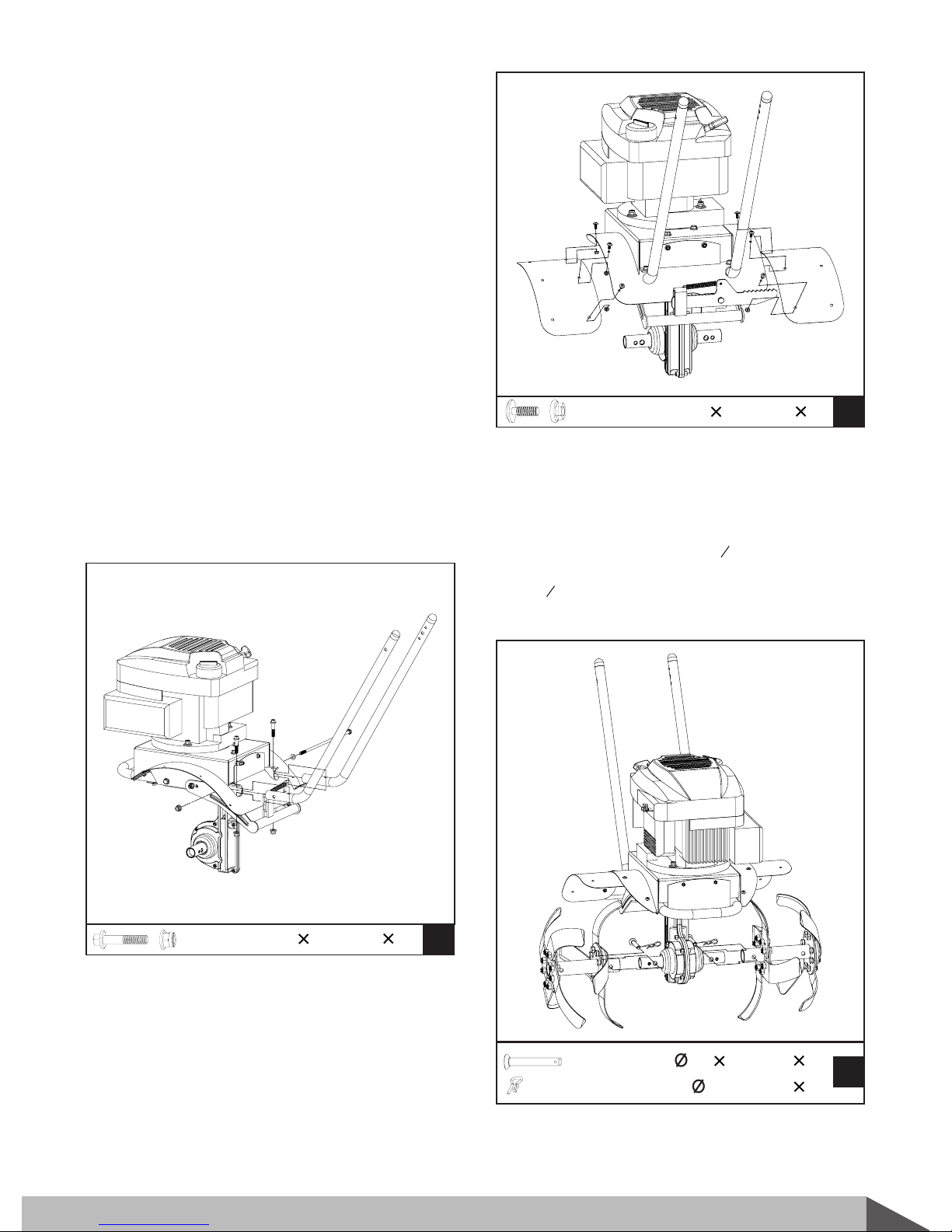
Lower handles
Remove the M8X260 screw, flat washer and
lock nut from the rear end of tiller chassis.
1.
Mounting holes for adjustment knob are
arranged in the top portion of each lower handle.
Make sure the 3-hole side of the handle is facing
inward. Insert the bottom portions of the lower
handles into the mounting channels located in
the underside of each side of the tiller chassis.
2.
Mount the flat washer on the M8X260 screw
removed. Line up the holes in the bracket,
handles and tiller chassis. Slide the screw
through the holes from one side, then lock nut
from the other side. Leave them untightened
at this time.
3.
Tilling tines
Place tilling tines on the tine shaft on both sides
of the gear box. Line up the holes in the tine frame
sleeves and tine shaft. Insert O10X50 clevis pins
through the holes in tine frames and tine shaft.
Insert O2.5 cotter pins through the holes in the
clevis pins to secure them.
On each side, slide on a M8X45 flange screw
through the holes in the mounting channel and
the lower handle, then screw a flange nut.
4.
B
M8 45 2
Tine shield extensions
Attach the tine shield extensions to the tine shield
with M5X12 screws and flange nuts.
C
6M5 12
D
210 50
22.5
7
Tighten down all the screws.5.
Mowerland Tiller

Depth regulator rod
Insert the depth regulator rod through hole in
the wheel bracket lock block from the top down
with curve to the rear of the unit and secure
with a O4 cotter pin through the holes in the
bracket lock block, passing through the desired
hole in the depth regulator rod.
Upper handle
Mount the upper handle on the lower handles
with the handle adjustment knobs.
2.
Disassemble the handle adjustment knobs.1.
Upper
Handle
Retainer
Cone
Bolt
Inside
Adjuster
Lower
Handle
Konb
Outside
Adjuster
Throttle & clutch controls
Remove the M6X60 carriage bolt and nut from
the throttle control assembly. Mount the throttle
control on the left side of the upper handle with
the hardware removed. Make sure the throttle
control is mounted outside the handle.
2.
Unwind the throttle control and clutch control
from around the engine. Straighten the cables.
Make sure that you do not bend or kink the
cables.
1.
Remove the M6X40 socket screw and nut from
the clutch control lever assembly. Mount the
clutch control lever on the right side of the
upper handle with the hardware removed. Make
sure the clutch control lever is mounted on the
top of the handle.
3.
Use two cable clips to secure the clutch control
cable and throttle control cable in place on the
lower handles. Attach the clutch control cable
to the upper handle with another cable clip.
Make sure the control cables are routed properly.
4.
F
Wheels bracket
E
2M10 20
3
8
Press down on the release pedal and insert the
lock block under the lock lever. Make sure the
spring-loaded lever locks in one of the grooves.
1.
Hook the wheel bracket on the tailpiece bracket
assembly.
2.
Secure the wheel bracket lock block on the
wheel bracket with two M10X20 screws and
teethed washers.
3.
Mowerland Tiller

Add oil according to Engine Manual packed
separately with your tiller.
Engine oil
KNOW YOUR TILLER
Features and Controls
G
14
Engine is shipped from factory without
oil. You must add engine oil before
starting engine.
Upper Handle
Lower Handle
Depth Regulator Rod
Wheel Support Bracket
Wheel
Handle Adjustment Knob
Tine Clutch Control
Throttle Control Lever
Wheel Bracket Release Pedal
9
Mowerland Tiller
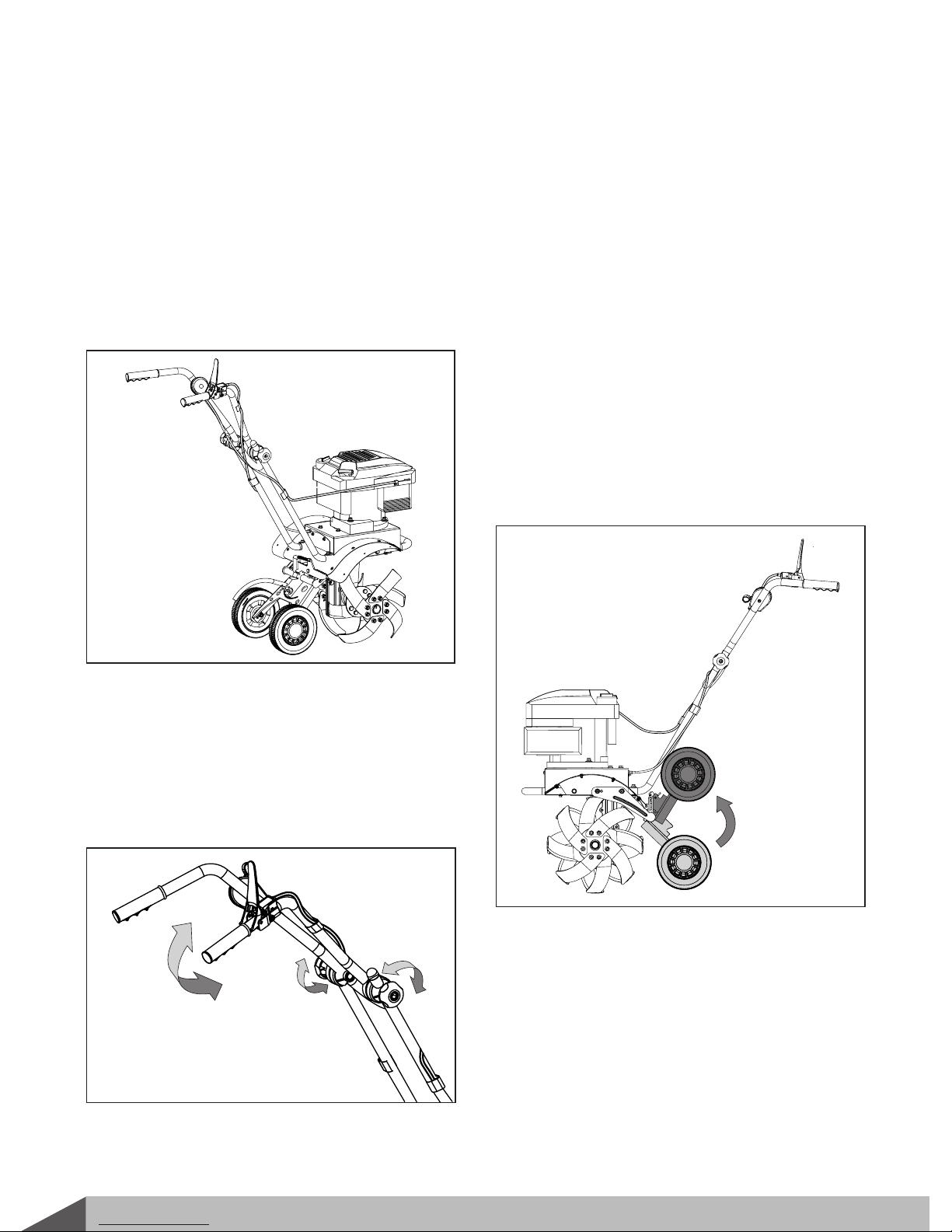
Handle adjustment knobs
Provides different handle heights for different tilling
conditions.
Loosen both handle adjustment knobs, and pivot
handle forward or backward to desired height,
then tighten the adjustment knobs securely.
Wheels bracket release pedal
The spring-loaded wheels bracket release pedal
locks wheels bracket with depth regulator rod
at different height and distance from the tines.
Press down on the wheels bracket release pedal
to release the wheels bracket. With the tines
touching the ground, an upward pressure on
the handles will fold the wheels bracket toward
the tines. With the wheels sitting on the ground,
a downward pressure on the handles will unfold
the wheels bracket away from the tines. Release
the pedal to lock the wheels bracket in the
desired position.
Throttle control
Controls the engine speed and stops the engine.
Tine clutch control
Pushing down to engage tines into forward.
Releasing returns machine to neutral.
Transport wheels
Set the wheels down and the depth regulator rod
with curve up when transporting the tiller. Tilt the
machine back until the tines clear the ground. Push
or pull the unit to the next location.
The unfolding and flexible wheels bracket with
depth regulator rod gives the tiller its versatility
and its stability. When the wheels bracket is
unfolded for tilling, the long length between the
tines and depth regulator rod provides more
comfortable operation.
10 Mowerland Tiller

Depth regulator rod
Serves a dual purpose. It regulates the tilling depth
and helps the operator control the direction and
speed of the tiller.
Unfold the wheels bracket to raise the wheels to
one of the high positions. Set the depth regulator
rod with curve down to the rear of the unit.
1. Remove the cotter pin.
Raise or lower the depth regulator rod.2.
Align groove in depth regulator rod with the
holes in bracket lock block and replace the cotter
pin.
3.
Lowering the depth regulator rod will slow the
tiller and make it till deeper. Raising the depth
regulator rod will allow it to move faster and till
more shallow.
To adjust the tilling depth.
For heavy soil (100mm / 4” depth or greater),
remove the depth regulator rod and work the tines
down with a back and forth motion to at least a
depth of 100mm (4”). Slowly pull the tiller backward
allowing the soil to feed forward over the tines.
Do not adjust tilling depth unless tine
clutch control lever is released to the
neutral position.
Besides obtained from the wheels bracket
adjustment, the depth regulator rod can be
adjusted through its grooves.
11
Mowerland Tiller

Tiller Operation
Adding fuel
Fill the fuel tank as instructed in the separate
Engine Manual packed with the tiller.
Starting engine
The controls required to start and run the tiller are
located on the engine and are marked “CHOKE”
and “THROTTLE”. Throttle can be adjusted by the
throttle control lever mounted on the left upper
handle through a control cable.
A more detailed description of the engine operation
and all related precautions and procedures can be
found in the Engine Manual packed separately
with the tiller.
Follow the procedure below for cold starts:
1. Turn choke lever on the engine to full choke
position.
2. Set the throttle lever to “FAST” position.
3. Pull the starting rope slowly several times to
allow the gasoline to flow into the engine’s
carburetor. Then hold the start handle firmly
and pull rope out a short distance, until you feel
some resistance. Then pull the rope smoothly
and briskly, and allow rope to return gently. Do
not let the rope to snap back. If necessary, pull
the rope several times until the engine starts.
4. Allow the engine to run for several seconds to
warm up. Then, gradually move chock lever to
no choke position and adjust the throttle control
to desired speed.
5. Grip the handles firmly with both hands. Squeeze
down on the clutch control lever - this will
engage the tines and move the filler in a forward
direction.
Restarting an engine that is already warm from
previous running does not normally require use of
the choke.
1. Move throttle lever to “FAST” position.
2. Hold the start handle firmly and pull rope out
a short distance, until you feel some resistance.
Then pull the rope smoothly and briskly, and
allow rope to return gently. Do not let the rope
to snap back.
3. Adjust the throttle control to desired speed.
4. Grip the handles firmly with both hands. Squeeze
down on the clutch control lever to engage the
tine and move the filler in a forward direction.
Idle speed
Set throttle control lever to its “LOW” position to
reduce stress on the engine when tilling is not
being performed. Lowering the engine speed to
idle the engine will help extend the life of the
engine, as well as conserve fuel and reduce the
noise level of the machine.
Shutting down
1. Release tine clutch control lever to neutral
position to stop the tines.
2. Set throttle control lever to its “STOP” position
to stop the engine.
Operating speed
For normal tilling, set the throttle control lever to
“FAST” for best tiller action. The throttle should
be set to control forward movement to a slow
walking speed for cultivating. Set the throttle
control lever to “LOW” to reduce stress on the
engine when tilling is not being performed.
Besides depth regulator rod setting, variation of
pressure on the handles also helps further control
of tilling depth and travel speed. A downward
pressure on the handles will reduce the tilling depth
and increase the forward speed. An upward
pressure on the handles will increase the working
depth and reduce the forward speed.
Fill tank to no more than 12.5mm (1/2”)
below the bottom of the filler neck to
provide space for expansion.
Starting engine
Do not move choke control to CHOKE
to stop engine. Backfire or engine
damage may occur.
12 Mowerland Tiller

Tilling
Tilling is digging in, turning over and breaking up
garden soil and prepare a seedbed for planting.
Best tilling depth is 100mm (4”) to 150mm (6”). A
tiller will also clear the soil of unwanted vegetation.
The decomposition of this vegetation matter
enriches the soil.
Avoid tilling soil that is too dry as it will pulverize
and produce a dust that will not hold water. Water
a few days before tilling. Also, tilling soil that is
too wet will produce unsatisfactory clods. Wait a
day or two after heavy rain for the soil to dry.
Better growth will be obtained if an area is tilled
properly and used soon after tilling to preserve
the moisture content.
The type of soil and working conditions will
determine the actual setting of the tilling depth.
In some soils, the desired depth is reached first
pass over garden. In other soils, the desired depth
is obtained by going over the garden two or three
times. In later case, the depth regulator rod should
be lowered before each succeeding pass over the
garden. Passes should be made across the length
and width of the garden alternately. Do not try to
dig too deeply in the first pass. If the machine
jumps or bucks, allow the unit to move forward
at a lightly faster rate.
If the tiller stops forward motion and tries to dig
in one spot, rock the handles from side to side to
start it moving forward again.
Rocks which are turned up should be removed
from the garden area.
Cultivating
Cultivating is loosening or digging around growing
plants to disrupt weeds and aerate soil. Less than
50mm (2”) depth is always desirable.
MAINTENANCE
Cleaning tine area
Keeping your tiller in top running condition will
prolong its life, and help you obtain optimum
performance whenever you wish to till your garden.
1. Turn off engine. Engine must be cool.
Clean the tiller underside of the tine shield after
each use. The dirt washes off tines easier if rinsed
off immediately instead of after it dries.
2. Keep the engine’s throttle control in its “STOP”
position, and remove spark plug wire from spark
plug and secure.
3. Remove all vegetation, string, wire, and other
materials that may have accumulated to the
axle between the inside set of tines and the
seals on the transmission housing.
4. Always towel dry the tiller afterwards and apply
a light coat of oil or silicone to prevent rusting
or water damage.
5. Replace spark plug wire.
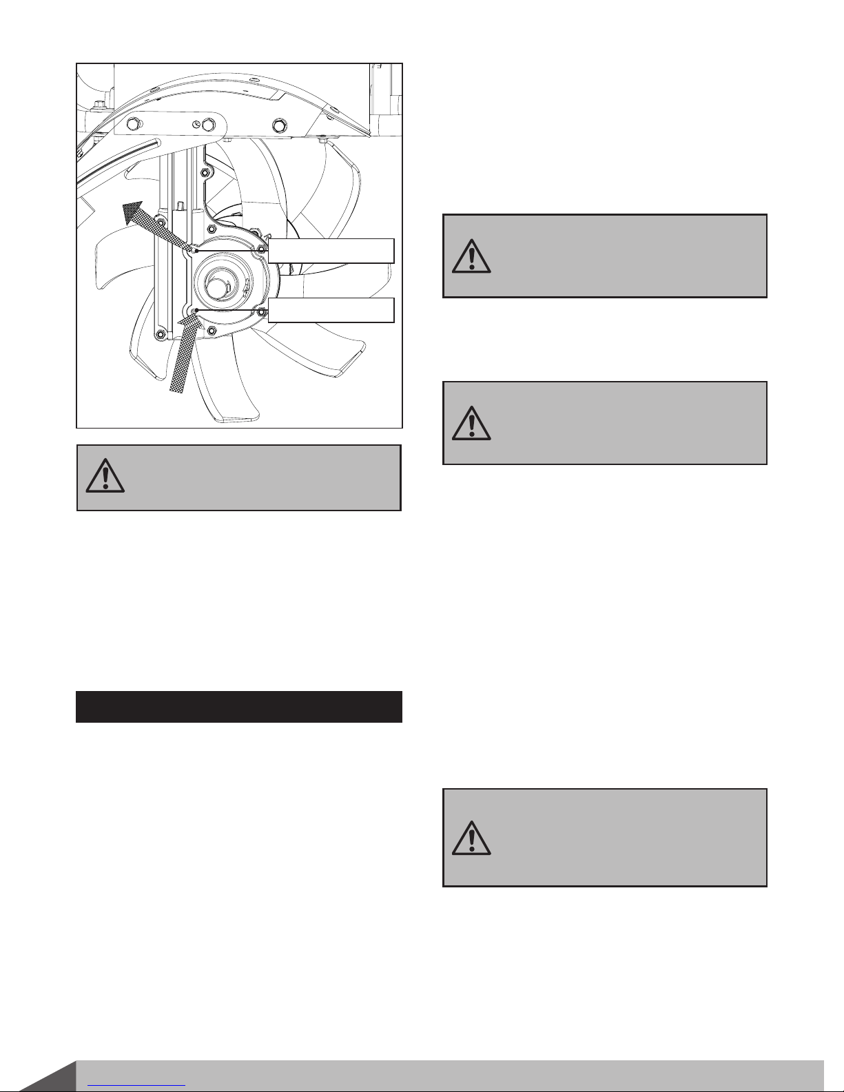
Lubrication
Remove the tine assemblies to lubricate the tine
shafts at least once a season.
The worm gear housing is pre-lubricated and
sealed at the factory. At the beginning of each
season, make sure enough lubricant inside the
worm gear housing. Use portable tool lithium #0
grease such as Lubriplate 6300AA , Lubriplate
GR-132, or Multifak, e.g. EP-O.
1. Remove right side tines and place the tiller on
level surface.
Allow the transmission to cool before filling with
grease.
2. Remove the grease fitting screw and air vent
screw to fill the worm gear housing through the
lower grease fitting hole until the grease begins
to come out from the upper air vent hole.
3. Reinstall the grease fitting screw and air vent
screw.
Never use a “pressure washer” to clean
your tiller. Water can penetrate tight
areas of the tiller and its transmission
case and cause damage to spindles,
pulleys, bearings, or the engine. The
use of pressure washers will result in
shortened life and reduce serviceability.
13
Mowerland Tiller
1. Drain the fuel tank completely. Stored fuel
containing ethanol or MTBE can start to go stale
in 30 days. Stale fuel has a high gum content
and can clog the carburetor and restrict fuel
flow.
2. Start the engine and allow it to run until it stops.
This ensures no fuel is left in the carburetor.
This helps prevent gum deposits from forming
inside the carburetor and possible engine
damage.
3. While the engine is still warm, drain the oil from
the engine. Refill with fresh oil of the grade
recommended in the Engine Manual.
4. Allow the engine to cool. Remove the spark
plug and put 30 ml (1 oz.) of high quality motor
oil into the cylinder. Pull the starter rope slowly
to distribute the oil. Replace the spark plug.
STORAGE
If the tiller will not be used for a period longer than
30 days, following the steps below to prepare your
tiller for storage.
5. Use clean cloths to clean off the outside of the
tiller and to keep the air vents free of
obstructions.
6. Inspect for any loose or damaged parts. Repair
or replace damaged parts and tighten loose
screws, nuts or bolts.
7. Remove the tines. Clean and apply oil to the
tines and tine shafts to prevent rusting. Mount
the tines onto the tine shafts.
8. Oil the control cables and all visible moving
parts. Do not remove the engine cover.
9. To store with the handles folded down, loosen
the knobs that secure the upper handle to the
lower handles. Carefully fold the upper handle
down. Do not allow control cables to become
pinched or bent. Tighten the knobs.
Refer to the Engine Manual included in your tiller
for the information on engine maintenance. Your
Engine Manual provides detailed information and
a maintenance schedule for performing the
maintenance.
Engine maintenance
Air Went Screw
Grease Fitting Screw
Do not overfill. Too much grease can
create pressure which could damage
seals.
Remove the spark plug and drain all
of the oil from the cylinder before
attempting to start the unit after
storage.
Do not use strong detergents or
petroleum based cleaners when
cleaning plastic parts. Chemicals can
damage plastics.
Do not sore tiller with fuel in a non-
ventilated area where fuel fumes may
reach flame, sparks, or any ignition
sources.
Use only approved fuel containers.
14 Mowerland Tiller

Problem Cause Remedy
Engine fails to
start.
1. Spark plug wire disconnected.
2. Out of fuel or stale fuel.
3. Throttle control lever not in correct
starting position.
4. Choke not in ON Position.
5. Blocked fuel line.
6. Fouled spark plug.
7. Engine flooding.
8. Tine clutch control not in neutral
position.
1. Attach spark plug wire securely to
spark plug.
2. Fill with clean, fresh gasoline.
3. Move throttle control lever to start
position.
4. Chock must be positioned at CHOKE
for a cold start.
5. Clean the fuel line.
6. Clean, adjust gap, or replace.
7. Wait a few minutes to restart, but do
not prime.
8. Tine clutch control lever must be
released to neutral to start the engine.
Engine runs
erratically.
1. Spark plug wire loose.
2. Unit running on CHOKE.
3. Blocked fuel line or stale fuel.
4. Vent plugged.
5. Water or dirt in fuel system.
6. Dirty air cleaner.
7. Improper carburetor adjustment.
1. Connect and tighten spark plug wire.
2. Move choke lever to OFF.
3. Clean fuel line. Fill tank with clean,
fresh gasoline.
4. Clear vent.
5. Drain fuel tank. Refill with fresh fuel.
6. Clean or replace air cleaner.
7. Refer to Engine Manual.
Engine overheats.
1. Engine oil level low.
2. Dirty air cleaner.
3. Air flow restricted.
4. Carburetor not adjusted properly.
1. Fill crankcase with proper oil.
2. Clean air cleaner.
3. Remove blower housing and clean.
4. Refer to Engine Manual.
Engine will not
stop when throttle
control is positioned
at stop, or engine
speed does not
increase properly
when throttle
control is adjusted.
1. Debris interfering with throttle linkage.
2. Improper throttle linkage adjustment.
1. Clean dirt and debris.
2. Refer to Engine Manual to check and
adjust throttle linkage.
Tiller moves forward
during starting. Tine clutch control not in neutral position. Tine clutch control lever must be released
to neutral to start the engine.
Tiller is difficult to
control when tilling
(machine jumps or
lurches forward).
1. Improper tilling depth setting.
2. Too high engine speed on hard ground.
1. Raise the tines for shallower tilling by
raising the depth regulator rod.
2. Set the throttle lever at lower speed.
Tines do not engage.
1. Foreign object lodged in tines.
2. Tine clevis pin(s) missing.
3. Belt worn and/or stretched.
4.Pulley and idler not in correct
adjustment.
1. Stop tiller completely, check and
discard foreign object.
2. Replace tine clevis pin(s).
3. Replace belt.
4. Contact dealer.
326400000M110
TROUBLE SHOOTING
15
Mowerland Tiller

PARTS SCHEDULE
16 Mowerland Tiller
Spares and Helpline 01793 333220

EC DECLARATION OF
CONFORMITY
Declaration of conformity
Pursuant to the regulations of the following EC
Directives:
- Machinery Directive 98/37/EC
Handy hereby declares that the product
Machine type: Mowerland Tiller
Machine model: MLTILL5
Conforms to the main safety requirements of the
EC Directives listed above.
This conformity is based on the following standards
and normative documents:
EN 709:1997+A1
EN ISO3744:1995
The responsible person, based within the EC, is
identified below
Name: Mr. Derek Belcher
Title: Managing Director
Company: Handy Distribution
Address: Hobley Drive, Stratton St Margaret,
Swindon, Wiltshire, SN3 4NS
Signature : Date: 8 th June 2007
17
ISO11094:1991
Mowerland Tiller
Table of contents
Popular Tiller manuals by other brands


Camon
Camon G11302 Operating instructions & safety notes

Wiedenmann
Wiedenmann Greens Terra Spike G6/135 operating instructions

White Outdoor Products
White Outdoor Products ROTO BOSS 310 instruction manual

Scheppach
Scheppach MTE450 Translation from the original instruction manual

Mantis
Mantis Tiller/Cultivator owner's manual

POTILA
POTILA MAGNUM PLUS Series operating instructions