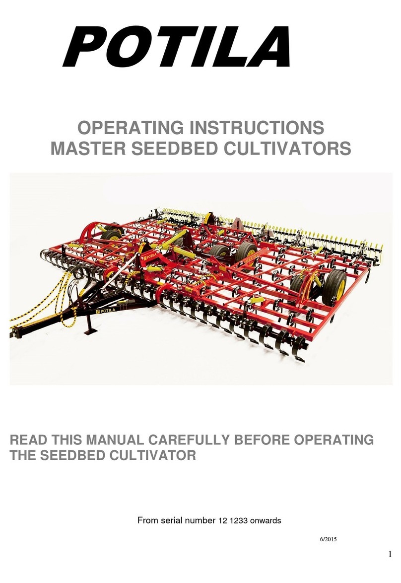
POTILA MAGNUM PLUS Series User manual

1
POTILA
OPERATING INSTRUCTIONS
MAGNUM PLUS SEEDBED CULTIVATORS
READ THIS MANUAL CAREFULLY BEFORE OPERATING
THE SEEDBED CULTIVATOR
From serial number
12 1233 onwards
6/2015

2
Contents
1.
INTRODUCTION............................................................................................................... 4
2.
SAFETY GUIDELINES..................................................................................................... 7
3. SETTING-UP.................................................................................................................... 11
4.
HARROWING.................................................................................................................. 23
5. MAINTENANCE .................................................................................. 25
6. WARRANTY.................................................................................................................... 35
EC DECLARATION OF CONFORMITY.............................................................................. 37

3
1. INTRODUCTION
Intended use
Technical specifications

4
1. INTRODUCTION
Intended use
POTILA MAGNUM PLUS seedbed cultivators are intended for preparing seedbed in
either the spring or fall. The field can be ploughed or cultivated, and it can contain
straw or other plant parts. The seedbed cultivator is used for loosening and crumbling
the soil after primary tillage to produce a level seedbed and well-crumbled topsoil.
The seedbed cultivator is NOT intended for primary tillage of untilled soil!
The open frame structure of POTILA MAGNUM PLUS seedbed cultivators enables
tine spacing that allows unrestricted, high-flow of soil. Level seedbed even on soft
soil types is ensured by the tines that keep their working depth, accurate working
depth control and large, high-capacity wheels.
POTILA MAGNUM PLUS seedbed cultivators are available with a wide range of
optional equipment to ensure optimal granular structure and level soil surface.
Rapid water infiltration,
high dispersion and
erosion resistance
Evaporation
boundary layer
Capillary
water rise
Nutrients,
oxygen
Figure 1. Recommended seedbed profile
(Heinonen 1971, page 85)
Working depth (cm)
seedbed
plough layer

5
Technical specifications
Type MAGNUM 700 800 900 1000 1100
PLUS
Number of sections 3 333 3
Working width, m 7,0 8,0 9,0 10,0 11,0
Number of tines 88 100 112 125 137
Number of tine axles 9 999 9
Draught requirement, kW 103 118 129 140 155
hp 140 160 175 190 210
Number of required hydraulic
outlets single-/double-acting -/3 -/3 -/3 -/3 -/3
Transport width, m 3,4 3,4 3,4 3,9 3,9
Working depth control
M = mech. H = hydr. H H H H H
Number of wheels 8 8 8 8 8
Wheel size 340 340 2340 340 340
Weight, incl. following harrow,
kg 4000 4300 4650 5150 5350
FEATURES FOUND ON ALL TYPES:
•Tine type 1145, cross-section of material 11 x 45 mm.
•Tine spacing 8 cm.
•Wheels 340/55-16”, diameter 780 mm, width 350 mm.
•Lights and reflectors.
•Hydraulically-controlled front crossboard as standard.
OPTIONAL EQUIPMENT:
•Following harrow with a tine diameter of 12 mm.
•Spiral rollers, diameter 27 cm.
Rear crossboard, controlled with front crossboard cylinders via linkage bars
or individually by the tractor's hydraulic system, in which case
3 double-acting hydraulic outlets are required.
•The number of rear equipment is limited to a maximum of 2 pieces
of equipment per seedbed cultivator.
•The standard front crossboard can be replaced with a 20-cm high full-wide
front crossboard constructed of heavy bulb flat steel profile.
•All models can be equipped with a spare wheel.

6
2. SAFETY UIDELINES
Warnings
Transport on roads

7
2. SAFETY GUIDELINES
Warnings
Pay special attention to all instructions and
diagrams marked with this symbol.
Read the manual carefully and make sure that you
understand everything. All safety guidelines must be
read carefully before hitching the seedbed cultivator
to the tractor. Learn how to operate the cultivator
carefully and in a correct manner.
CRUSHING HAZARD!
IMPACT HAZARD!
Keep a safe distance of 10 meters always when
the wing sections are raised or when the seedbed
cultivator is operated.
Never go under the cultivator unless it is supported.
CRUSHING HAZARD!
CUTTING HAZARD!
Crushing and cutting hazard when raising
or lowering the wing sections. Cutting hazard
when adjusting rear equipment. Crushing and
cutting hazard when hitching or unhitching the
seedbed cultivator.
FALLING HAZARD!
Climbing on the seedbed cultivator frame is prohibited.
Do not stay on the cultivator when it is being used
or transported.
HIGH HYDRAULIC PRESSURE HAZARD!
High-pressure oil jet can penetrate skin and
cause serious injury!
High hydraulic pressure hazard when hitching
or unhitching the seedbed cultivator.
DANGER!
Check the operation of locking devices before
transporting the seedbed cultivator.

8
Instructions for the operator
- Never stay near the wing sections when they are in the raised position.
- Do not allow anyone to stay on the seedbed cultivator when it is being used
or transported.
- Raising and lowering the wing sections may only be done when the cultivator
is parked and HITCHED TO THE TRACTOR.
- Prevent the tractor from moving by applying the parking brake always before
hitching the cultivator or performing maintenance!
- Ensure that the wing sections are in the fully raised position and properly
locked before driving off.
- Close the valve in the middle section wheel cylinder before driving on public roads.
- Close the valve in the hose for wing sections before driving on public roads.
- When driving on public roads with the cultivator, exercise caution and obey all traffic rules.
- Before performing any maintenance on the cultivator, lower the wing sections and park
the cultivator on a firm, level surface.
- Before performing any maintenance on the hydraulic system, position the cultivator on
suitable jack stands on a firm surface.
- Always inspect the following cultivator components visually before driving on public roads:
The condition of the towing eye and its bolts.
The condition of the tyres and wheel bolts.
The condition of the draw bar and its bolts.
- Always use original spare parts for maintenance.
- Always observe the instructions and guidelines specified in this manual when adjusting,
operating and servicing the cultivator.
Wear safety goggles when performing maintenance.
Wear hearing protectors when driving.

9
Transport on roads
•Slowly raise the wing sections fully into the transport position. They are controlled
with the same hydraulic valve as the front crossboard during harrowing.
•Ensure that the automatic locking bars lock into their holes and do not drive
off before both wings are locked.
•Close valve A in the middle section wheel cylinder before transporting
the cultivator on a public road.
•Close valve D in the control hose for wing sections before transporting
the cultivator on a public road.
•Check that the cultivator is sufficiently clean before driving on a public road.
•Check the condition of the tyres and draw bar assembly.
•Check that the running lights are connected and that they work.
•Pay attention to the transport height.
•Drive carefully and obey all traffic rules.
Insufficient tyre pressure or high speed (over 40 km/h) may result
in damage to the tyres!
REMEMBER TO KEEP YOUR HANDS AWAY FROM THE HYDRAULIC
CONTROLS WHILE DRIVING ON THE ROAD!

10
1.
3. SETTIN -UP
Raising/lowering the draw bar
Hitching and hydraulics
Adjusting the seedbed cultivator
•Horizontal adjustment
•Middle section and wing section adjustment
•Depth adjustment
•Working depth indicator
•Use of the front crossboard
•Use of the rear equipment
Troubleshooting/FAQ

11
3.
SETTING-UP
Always observe the tractor's safety guidelines when hitching or unhitching the
seedbed cultivator. Crushing and cutting hazard when hitching or unhitching the
seedbed cultivator. Never disconnect or connect hoses that are under pressure.
Raising/lowering the draw bar
The draw bar of the seedbed cultivator can be raised to reduce the space needed
for storage (for example, in winter storage).
•Lower the support leg down.
•Lower the cultivator on its tines or jack stands.
•Unhitch the cultivator from the tractor tow hook but do not disconnect
the hydraulic hoses from the tractor.
•Use the wheel hydraulics control to loosen the draw bar so that the
draw bar top link can be detached.
•Disconnect the hydraulic hoses.
•Drive the tractor away from the cultivator.
•Attach the storage bar to the top link mounting point on the draw bar.
•Raise the draw bar using appropriate lifting devices and accessories.
Exercise extreme caution when raising the draw bar!
•Attach the other end of the storage bar to the frame with the top link pin.
•Remove any lifting accessories.
•Push the support leg to the upper position.
Lower the draw bar in reverse order.
Parking support Support leg

12
Hitching and hydraulics
Always observe the tractor's safety guidelines when hitching or unhitching the
seedbed cultivator. Crushing and cutting hazard when hitching or unhitching the
seedbed cultivator. Never disconnect or connect hoses that are under pressure.
•Hitch the cultivator to the tractor tow hook only.
•Ensure that the tractor tow hook locking is closed.
•Lift the support leg and lock it to the upper position.
•Connect the wheel transport hydraulic hoses (red) to a double-acting
hydraulic outlet (diameter 19 mm).
•Connect the depth control hydraulic hoses (blue) to a double-acting
hydraulic outlet (diameter 19 mm).
•Connect the front crossboard/wing section hoses (green) to a double-acting
hydraulic outlet (diameter 14 mm).
Wheel hydraulics
Depth control
Front crossboard/wing section control
+ –
+ –
+ –

13
•Open transport valves A and D. (The figure shows the valve in a closed position.)
•Lift the cultivator on its wheels.
•Drive the tractor with the hitched cultivator onto a firm, level surface.
•Lower the wing sections. Ensure that the wing section extension areas
are clear! For this procedure, the cultivator must be in the transport position.
•The automatic section locking opens before the wing sections start to move.
•Balance the hydraulic circuits if necessary.
Balancing the hydraulic circuits
When using the cultivator for the first time after a long break, fully extend the piston rods of
the cylinders connected in series using the wheel circuit hydraulics and keep the pressure
on in the wheel circuit with the tractor's hydraulic control lever for 1–3 minutes.
The cylinders are fully extended when 250 mm of the front crossboard cylinder piston
rods
are exposed. For the wheel hydraulics, the corresponding dimensions are as follows:
the middle cylinder 400 mm, wing section cylinders 290 mm.
This procedure will circulate hydraulic oil throughout the system, thus balancing motion
differences and bleeding any air bubbles.
Remember to balance the cylinders connected in series if necessary!

14
Adjusting the seedbed cultivator
NOTE! Ensure that the wing section extension areas are clear. Remember
the minimum safe distances!
Lower the wing sections as follows:
•If the cultivator is not in the transport position, lift the cultivator
all the way up on its wheels. (The change valve will then direct
the pressure to the wing section lift cylinders.)
•Ensure that the wing section extension areas are clear.
•Lower the wing sections carefully. The wing sections are lowered
with the front crossboard control lever. The transport locking will
open automatically when the wing sections begin to lower.
•Note that lowering the wing sections may create a vacuum in the
hydraulic circuit.
•Using the tractor hydraulics, run the piston rods of the wing section
lift cylinders all the way out until they are fully extended.
All models are equipped with change valve
assemblies that control the front
crossboard/wing section hydraulics. Their
purpose is to distribute the pressure of the
same hydraulic outlet to the front crossboard
cylinders or wing
section lift cylinders depending
on the position of the cultivator (work or
transport position).
Horizontal adjustment
The cultivator's horizontal straightness is adjusted by
turning this top link. The front end of the frame lowers
when the top link is retracted. Correspondingly, the
front
end rises when the top link is extended. This
adjustment ensures even working depth of all tines.
Lower the cultivator on its tines so that the top link is
loose. Open the top link lock plate. Adjust the top
link to the correct length by turning it. Lock the lock
plate.
Because the adjustment of this position depends on the height of the tractor tow hook,
it must always be readjusted when hitching the cultivator to a different tractor.

15
MIDDLE SECTION AND WING SECTION ADJUSTMENT:
B
A
•The height of the middle section is aligned with the height of the wing sections
by turning the piston rod of the middle cylinder (B).
•When the rod screw is extended, the middle section rises. Correspondingly,
when the rod screw is retracted, the middle section lowers in relation to the
wing sections.
•The end piece must be locked with the lock nut after adjustment.
•No more than 15 mm of thread may be exposed.
•Check this setting in the field before starting to harrow.
Lower the cultivator on its tines so that the mounting bolts of the cylinders
have some play. Shut down the tractor! Pay special attention when you move
between the frame of the cultivator to access the end piece to be adjusted.
Never walk or stand on the frame!

16
C
The relative height of the wing sections can
be adjusted by turning the cylinder piston rod.
The end piece must be locked with the lock nut after
adjustment. No more than 15 mm of thread may be
exposed. Also check this setting in the field.
Lower the cultivator on its tines so that the mounting bolts of the cylinders have
some play. Shut down the tractor! Pay special attention when you move between
the frame of the cultivator to access the end piece to be adjusted. Never walk or
stand on the frame!

17
WHEEL HYDRAULICS AND DEPTH CONTROL
The hoses for the wheel hydraulics control circuit are marked with red.
The hoses for the depth control circuit are marked with blue.
Valve A-A
Valve B-B

18
The working depth is controlled hydraulically:
•Check that the hoses are properly connected (+/–). Connect the
hoses marked with the same colour to the same tractor valve.
•Fully retract the cylinder piston rods of the wheel hydraulics with
the wheel circuit valve A–. The line is indicated in red in the figure.
•Select the control valve for the depth control circuit (the line
indicated in blue in the figure) and fully retract the piston rods
with valve B–. Then run the piston rods out with valve B+ until
the desired working depth is reached. You can check the
working depth from the working depth indicator.
•
The working depth is now set. You do not need to use the depth
control valve B-B unless you want to adjust the working depth.
The cultivator is lifted and lowered with the wheel circuit valves
A+ and A–. The line is indicated in red in the figure
.
Hose markings: Red = A-A = Wheel hydraulics
Blue = B-B = Depth control
The working depth must be measured from harrowed soil behind the cultivator and
adjusted separately for each field and crop.
The working depth can be adjusted with valve B-B when driving.
The actual depth must always be checked by measuring
harrowed soil behind the cultivator.
Take measurements for each section.

19
Working depth indicator
Magnum Plus seedbed cultivators are equipped with a working depth indicator which
indicates the depth in centimetres. Adjust the indicator as described below.
The indicator is set to 0 at the factory, indicating the position in which the tines
and wheels are at the same level.
When beginning harrowing, check the setting as follows:
•Measure the working depth behind the cultivator.
•Loosen the screws indicated with “a” in the figure.
•Turn the assembly until the indicator shows the measured value.
•Tighten the screws.
•Check the movement of the bar.
Use of the front crossboard
The front crossboard control only functions when the cultivator is in the working
position, i.e. the tines are in the ground.
The front crossboard must be adjusted so that it levels the ploughed soil and transfers
a row of soil equal to the height of the points in front of it. The position of the front
crossboard can be controlled hydraulically while underway according to the soil type
and need for levelling.
a

20
Use of the rear equipment
The tractor must be shut down and the parking brake must be applied when
adjusting the rear equipment.
E
F
The position of the following harrow can
be adjusted at points E and F. On clay soil,
the following harrow most effectively turns
fine soil to the right sowing depth if the tines
are nearly perpendicular to the ground and
the harrowing speed is 8–10 km/h.
Spring adjustment
When using a spiral roller for rear equipment, the
roller is loaded by a draw spring. This spring should
not be tightened excessively – the tension is correct
if the soil surface is levelled and no traces of tines
can be seen behind the roller. When the roller is
used, the harrowing speed can be slightly higher
than when using a rear crossboard, i.e. 8–12 km/h.
The spiral roller and following harrow can also
be used simultaneously.
If necessary, the following harrow can be turned
up and locked with a pin.
Suitable harrowing speed for this combination
is 8–10 km/h.
Control with a linkage bar
Control with a dedicated hydraulic circuit
The rear crossboard control options are as follows:
•Control with the front crossboard hydraulic circuit, in which case
the movement is conveyed to the rear crossboard via a linkage
bar.
In this case, the relative position of the rear crossboard is adjusted
with a crank connected to the linkage bar.
•Control with a dedicated hydraulic circuit, in which case the rear
crossboard is controlled by separate cylinders connected in
series. The hoses for this circuit are marked with yellow.
This manual suits for next models
5
Table of contents
Other POTILA Tiller manuals