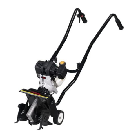
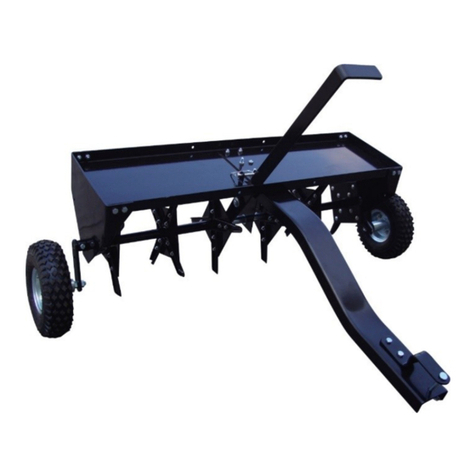
WilTec 51707 User manual

Operation Manual
ARTICLE 51707
40” Lawn Aerator
Read and follow the operating instructions and safety information before using for the first time.
Technical changes reserved!
Due to further developments, illustrations, functioning steps and technical data can differ
insignificantly.
Updating the documentation
If you have suggestions for improvement or have found any irregularities please contact us.
© by WilTe Wildanger Te hnik GmbH Seite 16
http://www.WilTe .de
http://www.aoyue.eu
http://www.tei htip.de

The information contained in this document is subject to change without prior notice. o part of this
document can be copied or duplicated in another form without the prior written consent of WilTec
Wildanger Technik GmbH. The WilTec Wildanger Technik GmbH assumes no liability for any errors in
this user manual or the connection diagram.
Although WilTec Wildanger Technik GmbH has made every effort to make sure that this user manual
is complete, accurate and updated, errors cannot always be avoided. In the event of problems with
this user manual please complete and send this form back to us.
FAX-notifi ation (+++49 2403 55592-15),
from: ________________________________________
Name: ________________
Firm:_____________________
Tel/Fax:__________________
I would like to report the following mistakes:
_______________________________ ____________________________________
Customer Service WilTec Wildanger Technik GmbH
e-mail: servi e@WilTe .info
Tel:++ +49 2403 55592-0
Introdu tion
Thank you for purchasing this quality product. To minimize the risk of injury by means of fire or
ele tri sho k we urge that our lients take some basi safety pre autions when using this
devi e. Please read the operation instru tions arefully and make sure you have understood its
ontent.
Always use a grounded power connection with the appropriate mains voltage. You can
nd the corresponding mains voltage on the type plate. If you have any doubts about the
connection being grounded, have it checked by a qualied professional. Never use a
faulty electric cable.
o not inspect the electrical part of the pressure pond lter in a wet or damp
environment or when you are wet yourself and protect it from direct sunlight. Install this
device in a safe location so that nobody can step on the cable, fall over or damage it.
isconnect the power plug before cleaning it and use only a damp cloth for cleaning.
Avoid using cleaning agents and make sure that no liquid enters the electrical part of the pump.
The electric part of the device contains no parts that can be inspected or serviced by the user. Leave
the maintenance, adjustment and repair to qualified technical personnel. In case of unauthorised
intervention the 2-year warranty is no longer valid! Keep these operation instructions safe.
© by WilTe Wildanger Te hnik GmbH Seite 17
http://www.WilTe .de
http://www.aoyue.eu
http://www.tei htip.de

NOTES ON SAFE OPERATION
Remember that any electrical device may cause personal injury if operated improperly or if the user
does not understand the operation of the device.
CAUTION: VEHICLE BRAKES AND STABILITY CAN BE AFFECTED BY THE ADDITION OF AC-
CESSORIES OR ATTACHMENTS AND ALTER THE DRIVING CHARACTERISTICS.
Always be careful when using an electrical device.
1. Read these operating instructions carefully before operating the device. Familiarize yourself with
the proper use of this equipment.
2. Read the manual and learn how to operate the unit before using it.
3. ever allow children to operate the tractor or the lawn aerator, and never allow adults to work with
it without proper instruction.
4. This lawn aerator has sharp knife tips. Always handle the appliance with care and wear safety
shoes.
5. Do not let anyone ride or sit on the frame of the lawn aerator or on the hitch.
6. Keep the area of use free from all persons, especially small children and pets.
7. Always start with the gearbox in the first (lowest) gear and at low speed and gradually increase the
speed as conditions allow.
8. The braking behaviour and stability of the towing vehicle may be affected by the attachment of the
lawn ventilator. Pay particular attention to the changing conditions at steep gradients. Observe the
safety regulations in the operating instructions for safe operation on slopes.
9. ever work across a slope, but always up and down.
10. This device should be operated at reduced speed in uneven terrain, along streams and ditches,
and on slopes to prevent overturning or loss of control. Do not drive too close to a stream or ditch.
11. Do not tow this unit on a highway or other public road.
12. Follow the maintenance instructions as described in this manual.
© by WilTe Wildanger Te hnik GmbH Seite 18
http://www.WilTe .de
http://www.aoyue.eu
http://www.tei htip.de

SCOPE OF DELIVERY
No Des ription
1 Plate
2 Central Support
3 Side Plate (x2)
4 Handle
5 Coupling Rod
6 Axis
7 Clutch
8 Wheel (x2)
9 Wheel Holder (x3)
10 Double Coil (x2)
26 Single Coil (x2)
CONTENT ASSEMBLY PACKAGE
© by WilTe Wildanger Te hnik GmbH Seite 19
http://www.WilTe .de
http://www.aoyue.eu
http://www.tei htip.de
No Qty Des ription No Qty Des ription
A
B
C
D
E
F
G
H
I
J
2
3
6
8
8
1
1
1
2
2
Screw 1/2” x 4-7/16”
Screw 1/4” x 1-9/16”
Screw 5/16” x 1-3/16”
Screw 5/16” x 7/8”
Screw 5/16” x 1”
Locking Pin
R-Pin
Coupling Pin
Hexagon ut 1/2”
Locking ut 1/2”
K
M
P
Q
R
S
T
U
V
W
22
12
4
8
1
1
3
1
1
1
Locking ut 5/16”
Washer Ø8
Washer Ø20
Spacer 1/4” lang
Spacer 1,61” lang
Spacer 0,79” lang
Locking ut 1/4”
Spacer 2,36” lang
Guide Disk
Spacer 2,76” lang
ASSEMBLY INSTRUCTION
Re ommended tools for assembly
2x – combination wrench 7/16” / 1/2” / 3/4”
1x – adjustable spanner – medium size
1x – medium sized pliers
Before mounting the aerator, lay out all parts as shown on the previous pages.
ATTENTION: THE TIPS OF THE AERATOR BLADES ARE SHARP! BE CAREFUL WHEN INSTAL-
LING AND USING THE LAWN AERATOR.
Step 1: Fasten the wheel holder to the axle shaft
1. Attach a wheel bracket to the middle opening of the axle shaft. ote that the wheel retainer ring
should point to the shortest side of the axle. Fasten
the wheel mount with a 1/4" x1-9 / 16" hex bolt and
a 1/4" hex lock nut. Do not tighten firmly.
2. ext, from the short side of the axle, insert a
5/16" x 1-3 / 16" hexagonal bolt into the hole on the
wheel bracket closest to the axle. (Smaller hole)
Attach the 5/16" Hex Lock ut to the bolt.
Do not tighten s rews.
Step 2: Mount the short side of the axle shaft.
© by WilTe Wildanger Te hnik GmbH Seite 20
http://www.WilTe .de
http://www.aoyue.eu
http://www.tei htip.de

Mount the lower parts on the short side of the axle shaft in the following order. Observe the direction of
the insertion knives.
1. Start with a double coil (knife to the outside)
2. Single coil (knife to the outside)
3. 2.36 " Spacer long
4. Ø20 Washer
Step 3: Mount the long side of the axle shaft
Mount these parts in the following order on the long side of the axle shaft. Observe the direction of the
insertion knives. IMPORTA T: Make sure that the upper bracket of the centre support faces the short
end of the axle!
1. Start with a 0.79" spacer
2. Ø20 Washer
3. Central support
4. Ø20 Washer
5. 1,61” Spacer
6. Double coil (knives point inwards)
7. Single coil
8. 2,76” Spacer
9. Ø20 Washer
© by WilTe Wildanger Te hnik GmbH Seite 21
http://www.WilTe .de
http://www.aoyue.eu
http://www.tei htip.de

Step 4: Fasten the end plates and the wheel holder
Start by turning the wheel holder in the middle of the axle shaft so that it points upwards. ext, attach
a side plate to one side, followed by a Ø20 washer and a wheel holder. ote that the wheel carrier ring
is facing inwards. Fasten the wheel bracket to the axle shaft with 1/4" x 1-9 / 16" hexagonal bolt and
1/4" counter nut. Tighten the connection firmly. Re- peat
for the other side.
1. Side plate
2. Wheel holder
3. Screws 1/4”x1-9/16”
4. Locking nut 1/4”
Step 5: Atta h the Wheel Assembly
Insert a 1/2" x 4-7 / 16" hex bolt through the wheel assembly, install the 1/2" hex nut onto the 1/2" x 4-
7 / 16" hex bolt and hand-tighten. Then loosen the hex
nut 1/2 turn. Attach the mounted wheel and screw the
1/2" x 4-7 / 16" hex to the wheel bracket and secure
with a 1/2" lock nut. Repeat for the other side.
Make sure that the wheels are turn freely after as-
sembly.
1. Wheel mounting
2. Hexagon head screw 1/2” x 4-7/16”
3. Hexagon nut 1/2”
4. Locking nut 1/2”
© by WilTe Wildanger Te hnik GmbH Seite 22
http://www.WilTe .de
http://www.aoyue.eu
http://www.tei htip.de

Step 6: Mounting the oupling rod and hook
Attach the coupling bracket to the tongue using the 5/16" x 1" hexagonal bolt and 5/16" hexagonal lock
nut. ext, insert the coupling pin through the coupling
holder and secure the tongue with the R-pin. Tighten
the connections tightly.
1. Coupling rod
2. Hexagon head screw 5/16” x 1”
3. Locking nut 5/16”
4. Coupling hook
5. R-Hook
Step 7: Fastening the oupling rod to the support
Attach the coupling rod to the shelf with the large opening of the compartment slot facing forward.
Tighten the rod with the upper shaft holes on the right side of the slot (seen from the front). For the
right side spring connection holes (front view) use a 5/16" x 1-3/16" screw, two 1/4" spacers per screw,
and a 5/16" hex lock nut. For the left side of the
connection, use a 5/16" x 1" bolt and a 5/16" hex
lock nut, not spacers. For holes to the left of the
storage slot (front view), use the 5/16" x 1-3 / 16"
hex bolt, two 1/4" spacers per bolt, and the 5/16"
hex lock nut.
Tighten all onne tions.
1. Hexagon head screw 5/16x1-3/16”
2. Hexagon nut 5/16” x 1”
3. Locking nut 5/16”
4. 1/4” Spacer
© by WilTe Wildanger Te hnik GmbH Seite 23
http://www.WilTe .de
http://www.aoyue.eu
http://www.tei htip.de

Step 8: Fasten the enter support
Position the tray between the side plates by hanging them into the plates. Temporarily attach the right
end plate to the top plate with two 5/16" x 7/8" screws (see Figure 8). Swing the middle strut into posi -
tion and secure with 5/16" x 1" screws and Ø8
washer and 5/16" hex lock nut.
Not omplete tighten.
1. Hexagon head screw 5/16” x 1”
2. Locking nut 5/16”
3. Central support
4. Spacer Ø8
Step 9: Atta h the top ompartment
Fasten both end plates to the top plate with 5/16" x 7/8" hex bolts, Ø8" washers and 5/16" hex nuts for
each corner (2 connections per corner). Repeat
these steps for each corner.
Do not tighten screws completely.
1. Hexagon head screw 5/16” x 7/8”
2. Locking nut 5/16”
3. Spacer Ø8
Step 10: Atta h the Lifting Handle
Place the lifting handle through the large opening in the storage slot. Attach the lifting handle to the
smaller opening in the wheel holder using the 5/16" x 1-3
/ 16" screw and the 5/16" lock nut that you pre-assem-
bled in step 2. Attach the lifting handle to a larger hole
using a 5/16" x 1-3 / 16" hexagonal bolt, spacer and
5/16" hexagonal lock nut.
Tighten the connections firmly.
1. Hexagon head screw 5/16” x 1-3/16”
2. Locking nut 5/16”
3. Spacer
© by WilTe Wildanger Te hnik GmbH Seite 24
http://www.WilTe .de
http://www.aoyue.eu
http://www.tei htip.de

Step 11: Adjust handle and tighten onne tions
Place the lawn aerator right side up on the wheels and lock the lifting handle into the offset at the front
of the storage slot. Perform the following steps to ensure correct alignment of the lifting handle with the
slot.
1. Adjust the compartment from side to side
so that the lifting handle rests on the
right side (seen from behind) of the off-
set on the front of the slot.
2. Align the side plates and then tighten the
eight screws at the corners of the com-
partment. Make sure that the lifting han-
dle is still on the right side of the slot off-
set.
3. Align the middle rail and tighten the two
screws that secure it to the tongue.
Make sure that the lifting handle is still on the
right side of the slot offset. You should bring the handle into alignment with the slot when lowering the
lawn aerator. The locking device is designed to help prevent the handle from slipping out when the
lawn aerator is in use. But if you feel that this part does not fit correctly, simply remove the pin.
© by WilTe Wildanger Te hnik GmbH Seite 25
http://www.WilTe .de
http://www.aoyue.eu
http://www.tei htip.de

OPERATION
Aeration involves pulling small cones, up to three centimeters long, out of the ground to cre-
ate small reservoirs that bring oxygen, fertilizer and water to the roots. For optimum perfor-
mance, the following lawn preparations and operating procedures are recommended.
ATTENTION: THE TIPS OF THE FAN BLADES ARE SHARP. CAUTION DURING USE.
1. Mow lawn and remove loose cuttings before using the lawn aerator.
2. Start the engine with the gearbox in neutral position and set the engine speed to a low
value.
3. Lower the gear lever to the lowest possible speed and the fan so that the fan blades can
penetrate the ground. Increase the speed only if conditions allow.
4. Drive on the lawn in straight, overlapping lanes to increase the ventilation capacity.
5. Avoid extremely sharp bends with blades embedded in the ground to avoid damage to
the lawn.
6. DO OT cross paths or roads without first switching the lawn aerator to the transport po-
sition.
7. Always drive on slopes and inclines from above or below. DO OT try to drive along the
slope.
8. To increase the penetration depth of the fan blades, up to 220 kg of weight such as sand
bags or concrete blocks can be placed on the tray. The weight can be attached to the
shelf with cable ties or straps attached to the front and back of the shelf. Fasten the
straps or ropes so that they cannot get caught in the rotating parts.
9. If the soil is extremely hard and dry, it is recommended that it is watered for up to two
hours before aeration.
10. Do OT try to ventilate if the ground is too wet (muddy).
11. Small stones and pebbles that come to the surface through ventilation should then be
collected so that other equipment, such as lawn mowers are not damaged.
ATTENTION: TO AVOID INJURY, DISCONNECT THE AERATOR FROM THE TRACTOR WHEN
LIFTING OR LOWERING THE FAN BLADES.
© by WilTe Wildanger Te hnik GmbH Seite 26
http://www.WilTe .de
http://www.aoyue.eu
http://www.tei htip.de

MAINTENANCE
1. Knife tips can be sharpened regularly with a small grinder to maintain good penetration.
Tips should be removed to sharpen them. Follow the original angle and contour of the
tips as you grind.
2. Before storage, clean the aerator and lightly oil exposed metal parts to prevent rusting.
LUBRICATION
1. Oil the coil units and the shaft as required.
2. Oil the wheel as required.
EXPLOSION DRAWING
© by WilTe Wildanger Te hnik GmbH Seite 27
http://www.WilTe .de
http://www.aoyue.eu
http://www.tei htip.de

PARTS LIST
No
.DESCRIPTION Qty. No
.DESCRIPTION Qty
.
1 Filing 1 19 Hexagon bolt 5/16” x 7/8” 8
2 Central support 1 20 Washer Ø8 12
3 Side plate 2 21 Hexagon bolt 1/4” x 1-9/16” 3
4 Lifting bracket 1 22 Coupling hook 1
5 Coupling rod 1 23 R-Hook 1
6 Axis 1 24 Hexagon bolt 1/2” x 4-7/16” 2
7 Coupling hook 1 25 Lock nut 1/2” 2
8 Wheel 2 26 Single coil 2
9 wheel suspension 3 27 Hexagon nut 1/2” 2
10 Double coil 2 28 Wheel suspension 8
11 Safety hook 1 29 Hexagon lock nut 1/4” 3
12 Hexagon bolt 5/16” x 1-3/16” 6 30 0.79” Spacer 1
13 Hexagon bolt 5/16” x 1” 8 31 1.61” Spacer 1
14 1/4” Spacers 8 32 2.36” Spacer 1
15 Point of a knife 24 33 Grip cap 1
16 Carriage screw 5/16” x 7/8” 48 34 Washer Ø20 4
17 Hexagon lock nut 5/16” 70 35 2.76” Spacer 1
18 Spacers 1
© by WilTe Wildanger Te hnik GmbH Seite 28
http://www.WilTe .de
http://www.aoyue.eu
http://www.tei htip.de
Disposal regulations
EU guidelines regarding the disposal of scrap electric appliances (WEEE, 2012/19/EU) were
implemented in the law related to electrical and electronic equipment and appliances.
All WilTec electric devices that fall under the WEEE regulations are labelled with the crossed-out
wheeled waste bin logo. This logo indicates that this electric equipment must not be disposed with the
domestic waste.
The company WilTec Technik GmbH has been registrated in the German registry EAR under the
WEEE-registration number DE45283704.
Disposal of used electrical and electronic appliances
(intended for use in the countries of the European
Union and other European countries with a separate
collection system for these appliances).
The logo on the article or on its packaging points out
that this article must not be treated as normal
household waste but must be disposed to a recycling
collection point for electronic and electrical waste
equipment. By contributing to the correct disposal of
this article you protect the environment and the health
of your fellow men. Environment and health are
threatened by inappropriate disposal.
Materials’ recycling helps reduce the consumption of raw materials.
Additional information on recycling this article can be provided by your local community, municipal
waste disposal facilities or the store where you purchased the article.
Address:
WilTec Wildanger Technik GmbH
Königsbenden 12 / 28
D-52249 Eschweiler
Important notice:
The reprint or reproduction, even of excerpts, and any commercial use, even in part of this instructions
manual require the written permission of WilTec Wildanger Technik GmbH.
© by WilTe Wildanger Te hnik GmbH Seite 29
http://www.WilTe .de
http://www.aoyue.eu
http://www.tei htip.de
Other manuals for 51707
1
Table of contents
Other WilTec Tiller manuals