MOZELT T4002 User manual

MOZELT GmbH & Co. KG
Load lifting magnet devices
Technical Manual
Electrical Power Supply System T4002
Please observe the following safety
information and recommendations
before start-up !
Copyright: MOZELT GmbH & Co. KG, D-47269 Duisburg Edition: Mai 2012
www.mozelt.com

1. General
During use the generator may have live, bare, if
applicable, also hot surfaces.
In the case of inadmissible removal of the required cover,
inappropriate use, wrong installaon or operaon, there
is the risk of death or severe injury or material damage.
All work concerning the transport, installaon and
start-up as well as maintenance are to be carried out by
qualied technical personnel (IEC 364 and/or CENELEC
HD 384 or DIN VDE 0100 and IEC Report 664 or DIN VDE
0110 and naonal regulaon for accident prevenon or
VGB 4 are to be observed). Qualied technical personnel
according to these basic safety references are persons
who are familiar with the installaon, assembly, start-up
and operaon of the product and possess corresponding
qualicaons for their acvity (dened in IEC 364 or DIN
VDE 0105).
For reasons of safety and the preservaon of
documented system data and funcons, repairs to the
generator or its components may only be undertaken by
the manufacturer.
Technical data, as well as data concerning connecon
condions, are to be taken from the rang plate and the
documentaon and are to be strictly observed.
2. Installation
The installaon and cooling of the devices must be
carried out according to the provisions of the respecve
documentaon.
The generators are to be protected against inadmissible
loads. They are only to be touched in such a way that no
components are bent and/or insulaon clearances are
changed. Avoid touching the electronic elements and
contacts.
3. Electrical connection
Installaons into which the generators are built must be
equipped, if necessary, with addional monitoring and
protecon devices.
The manufacturer’s documentaon is to be observed.
Aer separang the generators from the drive unit, live
components and line connecons must not be touched
when the generator spindle is running, due to the
voltage.
All covers are to be kept closed during operaon..
4. Operation
Installaons into which the generators are built must be
equipped, if necessary, with addional monitoring and
protecon devices.
The manufacturer’s documentaon is to be observed.
Aer separang the generators from the drive unit, live
components and line connecons must not be touched
when the generator spindle is running, due to the
voltage.
All covers are to be kept closed during operaon.
General information
MOZELT does not take any liability for the consequences
resulng from inappropriate, negligent or incorrect
installaon or operaon of the synchronous generator
with integrated electronics.
The condions of guarantee of MOZELT in the valid
version at the me of purchase shall apply for the
equipment.
The content of the present manual is considered correct
at the me of prinng for the indicated generator
version. MOZELT reserves the right to make changes
which represent a technical advantage.
Any change to the generators which is not performed
by us, including the installaon of addional devices,
can lead to a change of the technical specicaon and
the content of the documentaon and manual and
therefore leads to an exclusion of our liability, also from
the guarantee.
Safety information / General information
Englisch
MOZELT GmbH & Co. KG
Load liing magnet devices
Technical Manual: Electrical Power Supply T4002 www.mozelt.com
Copyright: MOZELT GmbH & Co. KG, D-47269 Duisburg Edition: May 2012 -2-
Englisch
MOZELT GmbH & Co. KG
Load liing magnet devices
Technical Manual: Electrical Power Supply T4002

Table of Contents
1. Technical descripon 4
1.1 Range of applicaons 4
1.2 Descripon 4
1.3 Funcon mode 4
2. Technical data 5
2.1 Performance data 5
2.2 Accessories 5
2.2.1 Mul-funcon display MFA 5
2.2.2 Electrical cable connecons 5
2.2.3 Generator drives 5
3. Assembly, drawings 6
3.1 Assembling instrucons 6
3.2 Connecons 6
3.3 Dimensional drawings of generator 7
4. Start-up 8
4.1 Safety informaon 8
4.2 Safety regulaons magnet operaon 8
4.3 Operang instrucons 9
4.4 Overview mul-funcon display MFA 10
4.5 Structural design of current supply 10
4.6 Operaonal indicators MFA 11
4.7 Fault indicators MFA 12
All passages in the manual which are marked with the symbol „Warning“ contain
informaon which is important to avoid danger!
WARNING
All passages in the manual which are marked with the symbol „Cauon“ contain
informaon which is necessary to avoid damage to the current supply or to accessory
equipment!
CAUTION
www.mozelt.com
Englisch
MOZELT GmbH & Co. KG
Load liing magnet devices
Technical Manual: Electrical Power Supply T4002
Copyright: MOZELT GmbH & Co. KG, D-47269 Duisburg Edition: May 2012 -3-

1.3 Funcon mode
The transformaon of brushless three-phase voltage
into DC voltage in the generator and its contactless
delivery aer acvang the generator provides the
operator with comfort and the highest safety.
The generator T 4002 is praccally maintenance-free.
The abolion of contactors or relay circuits in the
external electrical plant area, as well as the absence
of adjustment buons or potenometers, protects
this installaon system against faulty operaon and
sabotage.
The generator T 4002 is independent of the on-board
electrical system, and produces its own supply voltage
for internal control and monitoring. The machine is
overload and short-circuit proof.
The correct supply voltage is regulated automacally for
the magnet aached to the generator and the necessary
release me is opmized and implemented for every
kind of material to be loaded.
The operator can read o important operang condions
from the funcon display (MFA) in the operator‘s cab.
The display of the relave duty rang in % (ED) is to be
observed for the range 50% to 100% of the aached
load liing magnet. If this exceeds the value 80% ED, the
danger of the magnet overheang is signalized by a red
LED. It is then recommended to change the work mode
or to take a break to allow the magnet to cool down.
The localizaon of work related errors in the 220 V cable
system is directly possible. Cable damage and short-
circuits in the 220 V cable system lead to immediate
disconnecon of the supply voltage (passive protecon
for individuals).
1. Technical descripon
1.1 Range of applicaons
The MOZELT power supply system with synchronous
generator is designed to supply and acvate load liing
magnets on mobile excavators.
At present it is available with the output sizes 13, 20 and
30 kW.
Due to the duty rang of 100% (ED), the generators are
the opmal soluon for loading and handling in the
industrial scrap metal industry.
The maintenance-free and compactly designed
generator system is powered by the diesel engine of the
excavator or the hydraulic system.
1.2 Descripon
The rated speed of a generator of the
T 4002-series is around 3000 rpm*.
In this connecon, the range from
2600 rpm to 3400 rpm is to be
regarded as the tolerance range.
It is parcularly important that the
rotaonal speed remains constant
and no uctuaons occur!
With hydro-motor drives, maximum
speeds of up to 4000 rpm are
permied in the tripping torque of
the magnet, as long as they do not last
longer than 0.5 seconds. With rotaonal speeds above
3400 rpm and below 2600 rpm, magnet operaon is not
possible and/or is only limited.
The most important operang and switching states
are indicated in a mul-funcon display (MFA) in the
operator‘s cab.
The following displays are available for direct reading:
• Ready for use (ready)
• Magnet is liing
• Magnet is releasing
• Line interrupt
• R.P.M not ok
• Relave duty rang of 50 to 100% ED
• Short-circuit
www.mozelt.com
CAUTION
CAUTION
CAUTION
CAUTION
* rpm = revoluons per minute
Englisch
MOZELT GmbH & Co. KG
Load liing magnet devices
Technical Manual: Electrical Power Supply T4002
Copyright: MOZELT GmbH & Co. KG, D-47269 Duisburg Edition: May 2012 -4-
2. Technical data
2.1 Performance data
Model T 4002 13 kW 20 kW 30 kW
Rated voltage 230 V 230 V 230 V
Max. output current 56,5 A DC 87 A DC 130,5 A DC
Operang speed range * 2600....3400 rpm
Venlaon Internal venlator
Weight 58 kg 87 kg 135 kg
Protecon class IP 55
Permied ambient
temperature
-25° C…..+50° C non-condensing
Installaon height < 1000 m NN, above 1000 m output reducon of 1% per 100 m
2.2 Accessories
2.2.1 Multi-function display MFA
The dierent operang condions of the generator
are indicated in the funcon display (MFA) via LEDs.
An addional 6 LEDs indicate the working loading
ulizaon of the magnet (On/O rao) within the range
50…100%.
The release switch to turn the magnet on/o is also
aached to this display unit.
2.2.2 Electrical cable connections
The electrical cable connecons as well as the plug
connecons (plugs / coupler) are matched for the
respecve loads of the generators. The highest demands
are placed on funconality and safety.
If necessary, please use only original spare parts.
2.2.3 Generator drives
Depending on the version of the mobile excavator, the
generator is powered mechanically or hydraulically.
Both variants are designed in such a way that the
required rotaonal speed of the generator is ensured,
as soon as the diesel engine reaches its full speed.
With some hydraulic drives, opmal working is also
possible at low diesel speeds. In this respect, please check
the manual of the mobile excavator manufacturer.
Fig. 1 | Mul-funcon display MFA
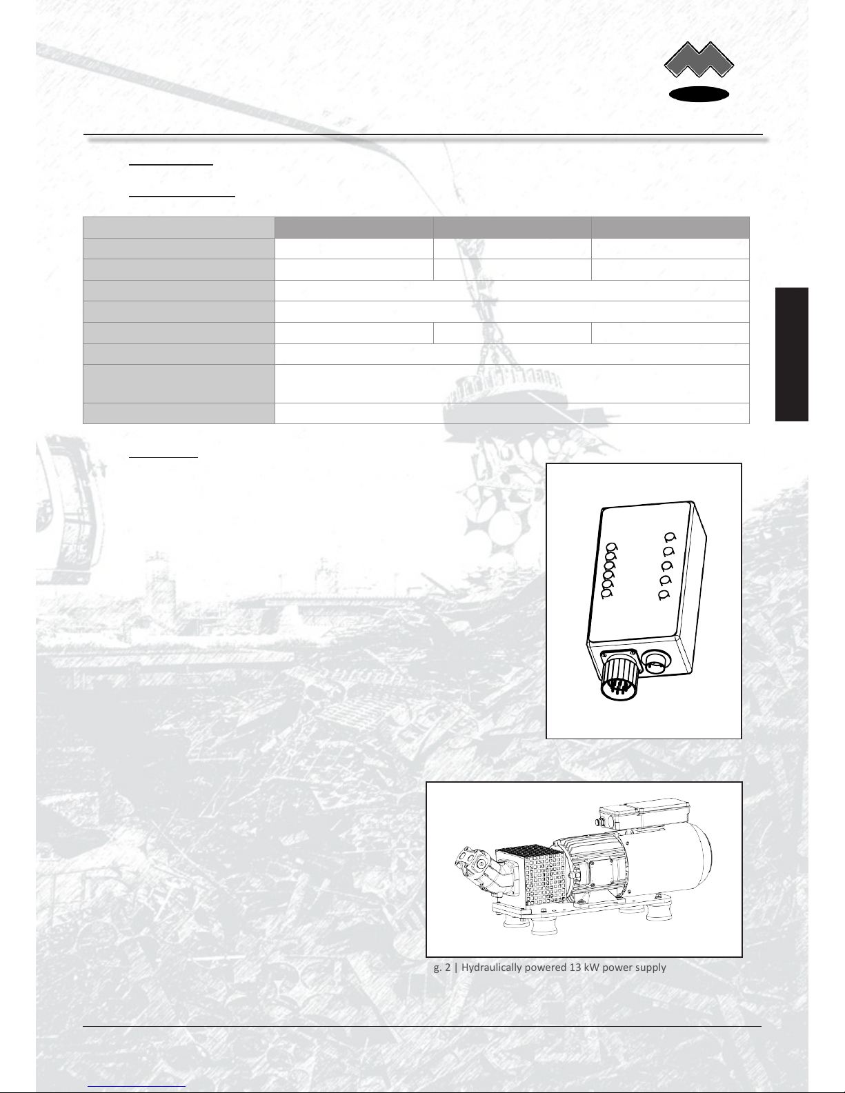
Fig. 2 | Hydraulically powered 13 kW power supply
www.mozelt.com
Englisch
MOZELT GmbH & Co. KG
Load liing magnet devices
Technical Manual: Electrical Power Supply T4002
Copyright: MOZELT GmbH & Co. KG, D-47269 Duisburg Edition: May 2012 -5-

3. Assembly, drawings
3.1 Assembling instrucons
The environmental atmosphere must be free of aggressive dust, corrosive vapours, gases and
liquids. The generator is to be protected against moisture according to IP 55.
Synchronous generators with integrated electronics may not be operated in areas classied
as dangerous, unless they are installed and cered in an approved housing.
The generators are designed for foot assembly.
Make sure that the heat produced by the generator can be dissipated. The venlator screen must always be kept free,
in order to ensure an adequate supply of fresh air.
All heat sources must be considered when determining the ambient temperature, so that the temperature does not
rise above the permissible maximum value for the generator.
3.2 Connecons
1
Protecve conductor connecon
Magnet connecon
Connecon for control cable to the MFA
1
2
3
Fig. 3 | Connecon box T4002 13 kW and 20 kW
Control electronics
2
1
3
Fig. 4 | Connecon box T4002 30 kW
1
2
3
www.mozelt.com
CAUTION
Englisch
MOZELT GmbH & Co. KG
Load liing magnet devices
Technical Manual: Electrical Power Supply T4002
Copyright: MOZELT GmbH & Co. KG, D-47269 Duisburg Edition: May 2012 -6-

3.3 Dimensional drawings of generator
Fig. 7 | Generator 13 kW DPE-0715
Fig. 6 | Generator 20 kW DPE-0815
Fig. 5 | Generator 30 kW DPE-0920
Spline sha
W 30 x 2 x 30 x 14 x 9g
DIN 5480
www.mozelt.com
Englisch
MOZELT GmbH & Co. KG
Load liing magnet devices
Technical Manual: Electrical Power Supply T4002
Copyright: MOZELT GmbH & Co. KG, D-47269 Duisburg Edition: May 2012 -7-

4. Start-up
4.1 Safety informaon
Read the operang instrucons before
start-up of the magnet device!
A visual check is to be made before start-
up of the complete system!
Ensure that the generator is ghtened
rmly before start-up!
Check the correct t of the drive belts
before start-up!
Only aach load liing magnets to the
system! Operaon for other electrical
users is not permied!
Before beginning work on the enre
system disengage the drive motor!
Never open the terminal connecon box
and the 220 V connector on the generator
and the magnet while the motor is
running!
Fig. 8 | Load liing magnets with various aachments
www.mozelt.com
4.2 Safety regulaons magnet operaon
The operaon of a load liing magnet on a mobile
excavator represents a special mode of operaon and
an increased safety risk. In contrast to working with a
hydraulic grabber, the magnet picks up all available
ferromagnec material immediately aer it is switched
on.
This may even be more than the load-carrying capacity
of the mobile excavator allows.
Similarly, the magnet suddenly releases the lied
material aer it is switched o, if there is cable damage
or a short-circuit in the magnet feed cable. This can
lead to dangerous situaons in the working vicinity, for
example, if falling material causes other objects to be
hurled up by lever force. Furthermore, it is not excluded
that pieces of scrap iron may separate from the magnet
during a swiveling procedure, if these are located at
the lower end of the lied material cluster. For these
reasons, it is parcularly important to observe the
following principle:
While working with the load
liing magnet it is forbidden to
stand within the extended reach of
the excavator
Do not swivel the working equipment
or change the locaon of the
excavator with the magnets
switched on without a
payload - unintenonally
lied materials can lead to
human injury by lever force!
The magnet can oscillate strongly aer load release!
For this reason, the mechanically safe aachment of
the magnet in the form of a special magnet suspension
at the end of the arm on the mobile excavator is highly
recommended!
WARNING
WARNING
WARNING
WARNING
WARNING
WARNING
WARNING
WARNING
WARNING
Englisch
MOZELT GmbH & Co. KG
Load liing magnet devices
Technical Manual: Electrical Power Supply T4002
Copyright: MOZELT GmbH & Co. KG, D-47269 Duisburg Edition: May 2012 -8-

4.3 Operang instrucons
When working with the load liing magnet, the pernent
industrial safety and accident prevenon regulaons are
to be observed.
In addion, liing magnet operaon may only be
started, if the operator knows the „Safety Regulaons
Magnet Operaon“ (see Table of Contents).
Before start-up of the power supply T 4002, the operator
should ensure that the 220V cable system is in an
opcally perfect condion. Plugs and plug connectors
are to be examined for ghtness of t, the anchoring
device of the magnet connecng cable is to be examined
for perfect funcon.
The V-belt tension with belt drives is to be examined and,
if necessary, the belts are to be reghtened according to
regulaon.
Unless otherwise expressly stated, the diesel engine
of the mobile excavator is to be brought up to full
revoluons. The generator then runs within its operang
range. The yellow LED „Ready“ automacally appears on
the mul-funcon display MFA I in the operator‘s cab.
Switching the power supply and/or the load liing
magnet on and o is usually accomplished with a
switch located in the handle. Depending on the type of
device, this must be energized with a separate switch
in the control console of the mobile excavator. For this
purpose also see the notes in the manual for the mobile
excavator.
If the switching-on command is given, then the generator
T 4002 connects the voltage contactless through to
the load liing magnet. If the command is given to
switch o, then the generator automacally leads to its
demagnezaon.
During the process of demagnezing, whereby the
magnet releases its load (approx. 1 sec), no renewed
switching-on command can be given.
Switching-on of the installaon is only possible, if a load
liing magnet is aached to the system.
Switching on the magnet:
Operate the buon in the control lever 1 x.
In addion to the yellow LED „Ready“, the green LED
„Power on“ lights up in the mul-funcon display.
Switching o the magnet:
Operate the same buon in the control lever again only
1 x.
The already illuminated green LED „Power on“ now goes
out and a red LED with „Power o“ lights up. Aer the
load has been dropped, this goes out automacally.
The permanently illuminated LED „Ready“ during the
shiing processes indicates that a renewed procedure is
now possible and that the power can be switched on.
Breakdowns are indicated by illuminated red LEDs.
The meaning and eliminaon of such disturbances are
explained using gurave illustraons and texts under
- Breakdown indicators on the MFA - (see 4.7 page
12/13).
Operaon with load liing magnet:
First place the magnet on the
material and then switch it on.
Swivel the magnet back in a
switched-o state.
Fig. 9 | Touch down of the switched-o magnet on the material
First ‘touch down’
of the magnet, then
switch it on !
www.mozelt.com
CAUTION
Englisch
MOZELT GmbH & Co. KG
Load liing magnet devices
Technical Manual: Electrical Power Supply T4002
Copyright: MOZELT GmbH & Co. KG, D-47269 Duisburg Edition: May 2012 -9-

1
2
3
4
5
6
Fig. 10 | Overview of the mul-funcon display MFA/MFD I
4.4 Overview mul-funcon display MFA
4.5 Structural design of current supply
The most important operang condions can be read
immediately:
Fig. 11 | Overview of structure power supply system T4002
8
7
9
6
123
54
1
2
3
4
5
6
7
8
9
Generator T4002
Mul-funcon display MFA/MFD I
Operang switch on the control lever
Switch cable
Control cable
Magnet cable 220 V
Connector
Magnet connecng cable
Load liing magnet
The essenal components are:
15
6
Funcon and breakdown indicators
(see 4.6 and 4.7 page 11-13)
Relave on-me of the magnec plate in %
www.mozelt.com
Englisch
MOZELT GmbH & Co. KG
Load liing magnet devices
Technical Manual: Electrical Power Supply T4002
Copyright: MOZELT GmbH & Co. KG, D-47269 Duisburg Edition: May 2012 -10-

4.6 Operaonal indicators MFA
Display: LED 1 (yellow), „Ready“
Note: Generator is waing for switching-on command.
1
Generator running in the working range
Fig. 12 | MFA indicates ready for
operaon
Display: LED 1 (yellow), „Ready“
LED 2 (green), „Power on“
Note: Magnet liing material.
1
Aer switching-on command given via operang switch, the magnet lis
Fig. 13 | MFA indicates an acvated
magnet
2
Display LED 1 (yellow), „Ready“
LED 3 (red), „Power o“
Note: Magnet releases the material.
1
Aer switching-o command given via operang switch, magnet releases
load
Fig. 14 | MFA indicates the release of the
material
3
www.mozelt.com
Englisch
MOZELT GmbH & Co. KG
Load liing magnet devices
Technical Manual: Electrical Power Supply T4002
Copyright: MOZELT GmbH & Co. KG, D-47269 Duisburg Edition: May 2012 -11-

4.7 Fault indicators MFA
LED 1 (yellow), „Ready“
- Interrupon in switch cable
- Operang switch defecve
- Control cable defecve
Aer switching-on command given via operang switch, no funcon
1
Fig. 15 | Switching-on command does
not react
LED 4 (red), „Line interrupt“
Aer switching-on command given via operang switch, „Line interrupt“
appears
4
Fig. 16 |MFA indicates „Line interrupt“
Aer switching-o command given via operang switch, LEDs ash
1
Fig. 17 | MFA indicates short-circuit
Display:
Possible cause:
Display:
Possible cause: - Cable break in the 220 V circuit
- Magnet aached wrongly or not aached
- Cable or connector defecve
- Magnet defecve
Display:
Posible cause:
LED 1 -5 (ashing),
- Short-circuit in the cable system 220 V
- Full earth fault of the magnet
- Magnet too much power for electrical supply
2
3
4
5
www.mozelt.com
Englisch
MOZELT GmbH & Co. KG
Load liing magnet devices
Technical Manual: Electrical Power Supply T4002
Copyright: MOZELT GmbH & Co. KG, D-47269 Duisburg Edition: May 2012 -12-

No LED indicator recognizable
- Cable damage / power breakdown in the
control cable
Generator runs within its working range, however, no funcon is
recognizable
Fig. 18 | MFA does not funcon
Only LED 5 (red), „R.P.M not o.k.“
The indicators „R.P.M not ok“ is lit up and the indicator „Ready“ is o
5
Fig. 19 | MFA indicates „R.M.P not ok“
The indicators „ R.P.M not ok „ and „Ready“ are lit up
1
Fig. 20 | MFA indicates a low speed
Display:
Possible cause:
Display:
Possible cause: - The generator is running too fast
Display:
Possible cause:
Note:
Turn o the engine immediately and have the
speed checked in order to prevent damage to the
generator !
LED 1 (yellow) „Ready“
LED 5 (red), „R.P.M not o.k”, possibly
also ashing
The generator is running too slow
Normal magnet operaon is only possible to a
limited extent; lower performance is to be expected
LED 5 (permanent), speed 2200 - 2400 rpm
LED 5 (ashing), speed 2400 - 2700 rpm
5
-
www.mozelt.com
CAUTION
Englisch
MOZELT GmbH & Co. KG
Load liing magnet devices
Technical Manual: Electrical Power Supply T4002
Copyright: MOZELT GmbH & Co. KG, D-47269 Duisburg Edition: May 2012 -13-
Table of contents
Popular Power Supply manuals by other brands

Toa
Toa VX-3150DS operating instructions

Cooper Notification
Cooper Notification Powerpath PS-8 installation instructions

Para systems
Para systems MM250XL/ 1 owner's manual

Sanyo
Sanyo VA-PS2440 Specifications

Universal Forest Products
Universal Forest Products DA-120-12W-1 manual

Altronix
Altronix LPS3C24X installation instructions
Siemens
Siemens LOGO!Power 6EP1311-1SH13 operating instructions

Behringer
Behringer Micropower PS400 manual

Cooler Master
Cooler Master UCP RS-700-AAAA-A3 user manual

KFV
KFV USV Series Description, Specification and Installation Instructions

Pulsar
Pulsar PSCV3512 quick start guide

CPS
CPS BP2592 Series instruction manual


