KFV USV Series User manual

FZ-USV-230 (SXM 2540)
Stand: 10.03.2008 1
KFV-USV Notstromversorgung
Beschreibung, Spezifikations- und
Installations-Anweisungen
KFV-USV Emergency Power Supplies
Description, Specification and
Installation Instructions

FZ-USV-230 (SXM 2540) [DE]
Stand: 10.03.2008 Seite 2 von 21
KFV-USV Notstromversorgung
Beschreibung, Spezifikations- und Installations-Anweisungen
KFV-USV Emergency Power Supplies
Description, Specification and Installation Instructions
Inhaltsverzeichnis / Table of Contents
──────────────────────────────────────────────────────
2
Deutsch 2
1. Beschreibung 3
2. Spezifikationen 4
3. Anschlussbelegung 5
4. Installations-Anweisung 5
5. LED-Status 10
6. Empfohlene Wartung 11
7. Dauer der Notstromversorgung 11
──────────────────────────────────────────────────────
12
English 12
1. Description 12
2. Specifications 14
3. Terminal Assignment 15
4. Installation Instructions 15
5. LED-Indications table 20
6. Recommended Maintenance 21
7. Battery Stand-By Mode Specifications 21
──────────────────────────────────────────────────────
Deutsch

FZ-USV-230 (SXM 2540) [DE]
Stand: 10.03.2008 Seite 3 von 21
1. Beschreibung
Die KFV FZ-USV-230 (SXM 2540) ist eine 12 Volt oder 24 Volt DC-
Notstromversorgung mit AC-Fehler- und Akku-Störungs-Überwachung über einen
potentialfreien Relaisausgang. Sie verfügt außerdem über LED Statusanzeigen (siehe
hierzu die Details in den nachfolgenden Spezifikationen) und wird in einem Wand-
Aufputzgehäuse geliefert. Die bestimmungsgemäße Verwendung ist in der 24 Volt
Einstellung der Notstromversorgung, in Verbindung mit bis zu 4 Genius oder 4
Fliethomatic`s.
1.1 Lieferumfang
Notstromversorgung bestehend aus:
•Metall Gehäuse incl. Trafo, und Ladeelektronik
•Akkus (optional müssen sep. bestellt werden)
•Kabeldurchführung
•Rasterband zur Kabelfixierung
•Drahtbrücken zum Anschluss an das Genius Kabel
•Akkudrahtbrücke um zwei 12 V Akkus in Reihe zu schalten
•Bohrschablone
•Anleitung
1.2 Allgemeine Hinweise
Unter Beachtung dieser Anleitung kann die Notstromversorgung problemlos montiert
bzw. in Betrieb genommen werden. Dabei darf der Einbau bzw. die Montage nur von
qualifizierten Fachbetrieben durchgeführt werden. Dies ist bei etwaigen
Reklamationen nachzuweisen.
Eigenmächtige Umbauten und Veränderungen an der Notstromversorgung und
dessen Zubehör sind nicht gestattet. Der Einbau von Fremdprodukten sowie die
Verwendung von nicht durch KFV freigegebener Teile können konstruktiv

FZ-USV-230 (SXM 2540) [DE]
Stand: 10.03.2008 Seite 4 von 21
vorgegebene Eigenschaften negativ verändern. Alle Reparaturen sind mit Original-
Ersatzteilen von autorisierten Fachleuten auszuführen. Für Schäden die aus
Nichtbeachtung dieser Anleitung entstehen, haftet der Hersteller nicht. Darüber hinaus
erlischt jede Art des Gewährleistungsanspruches.
Garantie: Für die Garantie gelten die jeweiligen gesetzlichen Bestimmungen.
Spuren des täglichen Gebrauchs (Kratzer, Dellen, kleine Risse usw.) stellen keinen
Garantiefall dar.
2. Spezifikationen
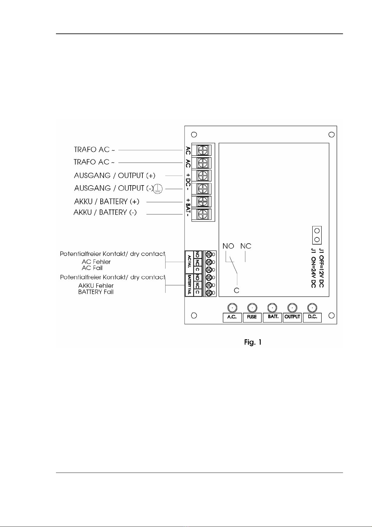
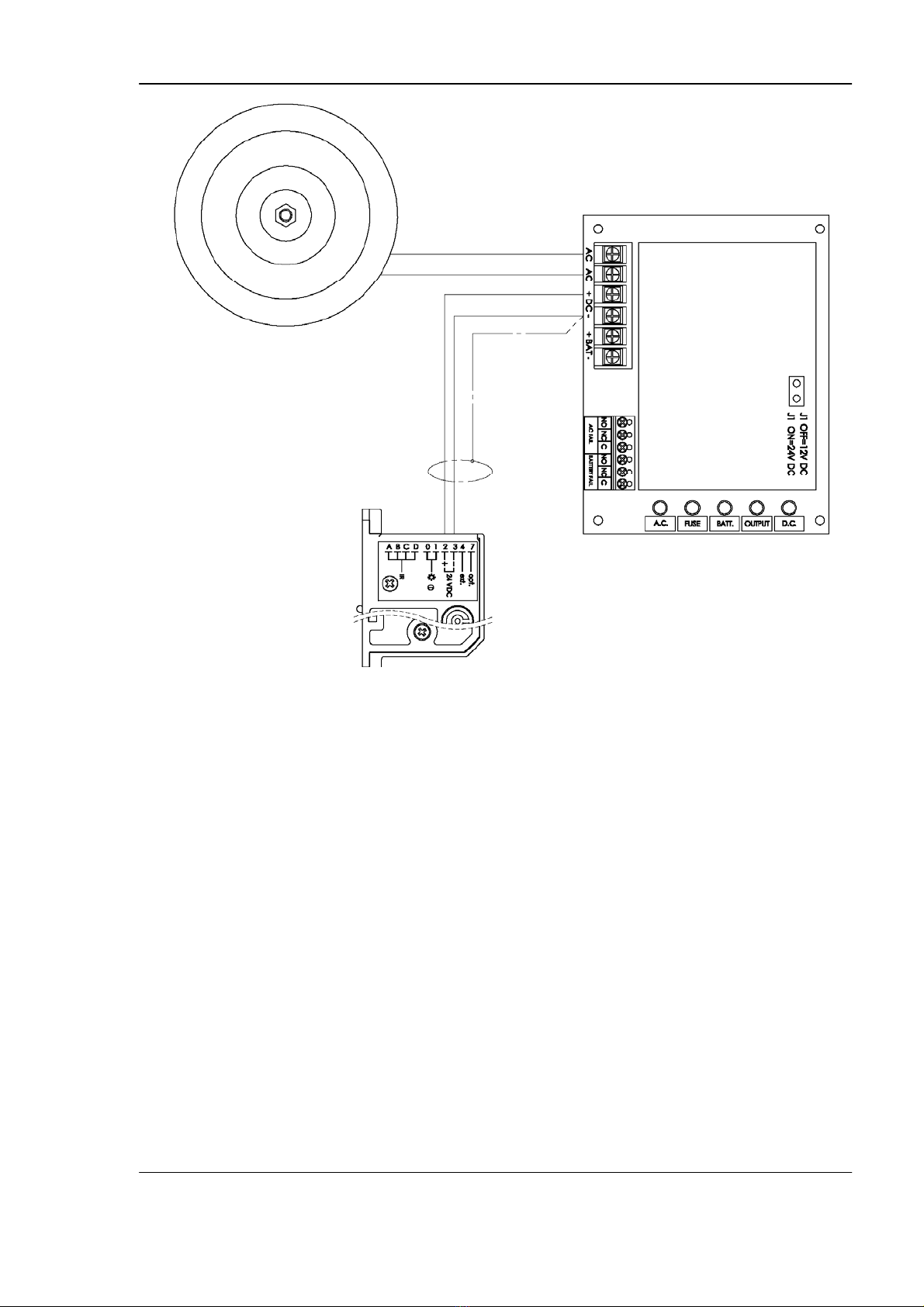
2.1. Ausgangspannung 12 VDC oder 24 VDC, über Jumper einstellbar.
2.2. Permanenter Ausgangsstrom 2 A
2.3. AC Fehlererkennung über potentialfreien Relaiskontakt
(Störungserkennung innerhalb von 1 Minute)
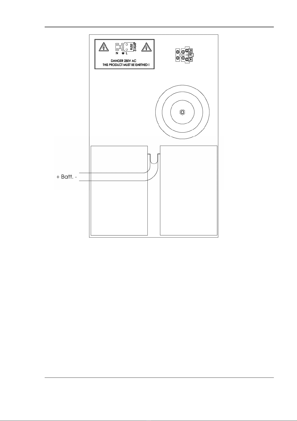
2.4. Integriertes Ladegerät für Blei- und Gelakkus
2.5. Sofortige Umschaltung auf Akkubetrieb bei erkanntem AC- Fehler
2.6. Akku Erkennung / Störungserkennung innerhalb von 1 Minute
2.7. Akku Unterspannungs-Abschaltung bei 9,9 VDC (12 V Jumper),
oder bei 19,9 VDC (24 V Jumper)
2.8. Batterie Überspannungs-Abschaltung bei 15 VDC (12 V Jumper)
oder bei 30 VDC (24 V Jumper)
2.9. LED-Anzeige bei Akku-Unterbrechung oder zu niedriger
Akkuspannung (L3 gelbe LED)
2.10. Akku-Fehlererkennung über potentialfreien Relaiskontakt
2.11. Akku Polaritätsschutz
2.12. Taste für Akku-Test
2.13. Thermischer Überlastungs- und Kurzschlussschutz
2.14. LED-Anzeige bei fehlerhafter Ausgangsspannung (L2 rote LED)
Überspannung-Fehler ab 29,6 Volt,
Unterspannungs-Fehler ab 21,0 Volt
2.15. Sicherung im DC Ausgang über PTC (thermische Sicherung)

FZ-USV-230 (SXM 2540) [DE]
Stand: 10.03.2008 Seite 5 von 21
2.16. LED-Anzeige bei PTC Aktivierung (L4 rote LED)
2.17. LED-Anzeige bei vorhandener AC-Versorgung (L5 grüne LED)
2.18. LED-Anzeige bei vorhandener DC-Ausgangsspannung (L1 grüne LED)
2.19. Gehäuse-Abmessungen; 230 mm x 350 mm x 85 mm
3. Anschlussbelegung
4. Installations-Anweisung
4.1. Montage
Das Gerät sollte in einem sicheren, trockenen Innenraum montiert werden, so das
eine Manipulation des Gerätes nicht möglich ist. Die Montage sollte an einer
stabilen Wand erfolgen. Es ist nicht für eine Außen-Installation geeignet.

FZ-USV-230 (SXM 2540) [DE]
Stand: 10.03.2008 Seite 6 von 21
Zur Montage bitte die drei in dem Gehäuse vorgestanzten Bohrungen , für die
Wandmontage nutzen (Bohrschablone). Der elektrische Anschluss des Gerätes
muss von entsprechend qualifizierten Personen und in Übereinstimmung mit
lokalen-, Nationalen oder Internationalen Normen und Vorschriften erfolgen.
4.2. Anschluss der AC-Spannungsversorgung
Bitte beachten Sie vor dem Anschluss der Versorgungsspannung den
Stromlaufplan im Anhang (siehe Fig. 1). Vor dem Anschluss der AC-Versorgung
bitte die richtige Position des Jumpers 1 überprüfen:
Jumper 1 OFF = 12 VDC
Jumper 1 ON = 24 VDC (Genius / Fliethomatic)
Die Höhe der Ausgangsspannung ist ab Werk auf den optimalen Wert eingestellt
und darf nicht verändert werden, ansonsten erlischt jeglicher Garantieanspruch.
4.3. Ausgangsspannung
Die Genius bzw. Fliethomatic wird mit den DC (+) und DC (-) der
Notstromversorgung verbunden (siehe Fig. 2). Bitte achten Sie auf die exakte
Polarität:
Klemme 2 = += DC (+)
Klemme 3 = ─= DC (-)
Masse (Abschirmung) = ─= DC (-) =

FZ-USV-230 (SXM 2540) [DE]
Stand: 10.03.2008 Seite 7 von 21
Fig. 2
4.4. Fehlererkennung / Ausgänge
AC-Fehlererkennung;- Bei einer korrekten AC-Versorgungsspannung ist das
Relais „AC-Fail“ angezogen. Eine Fehlererkennung erfolgt innerhalb von 1 Minute.
Wird ein Fehler erkannt fällt das Relais ab und die grüne LED L1 ist aus.
Akku-Fehlererkennung;- Sind die Akkus richtig angeschlossen und können
geladen werden, so ist das „Relais „Battery Fail“ angezogen. Eine
Fehlererkennung erfolgt innerhalb von 1 Minute, oder sofort, wenn die Akku-
Testtaste unterhalb der LED’s betätigt wurde. Wird ein Fehler erkannt, so leuchtet
die gelbe LED L3 und das Relais fällt ab.

FZ-USV-230 (SXM 2540) [DE]
Stand: 10.03.2008 Seite 8 von 21
4.5. Erste Inbetriebnahme
Bitte prüfen Sie die exakte Verdrahtung:
•der 230 VAC Versorgung
•Anschluss / Polarität der Akkus
•der richtige Anschluss / Polarität der Genius / Fliethomatic (24 Volt)
Bei der Einstellung für eine 24 Volt Ausgangsspannung werden zwei 12 Volt Akkus
in Reihe geschaltet (siehe Fig. 3).
Fig. 3
Bitte nutzen Sie hierfür die beiliegenden Kabel.
Platzierung der Akkus in das Gehäuse siehe Fig. 4.

FZ-USV-230 (SXM 2540) [DE]
Stand: 10.03.2008 Seite 9 von 21
Fig. 4
Wurde alles notwendige überprüft, so kann die 230 VAC Versorgung zugeschaltet
werden.
Die grüne LED L5 muss leuchten und das Relais „AC Fail“ zieht an.
Die grüne LED L1 muss ebenfalls leuchten und zeigt die korrekte DC-
Ausgangsspannung an.
Das Relais „Battery Fail“ muss ebenfalls anziehen.
Prüfen Sie die Funktionen der Genius / Fliethomatic (elektrisches Ver- Entriegeln
und bei voll geladenen Akkus die gewünschten Funktionen im Falle eines
erkannten Fehlers –Umschaltung Tagbetrieb- siehe hierzu auch den
Verdrahtungsvorschlag im Anhang, Fig. 5).

FZ-USV-230 (SXM 2540) [DE]
Stand: 10.03.2008 Seite 10 von 21
Fig. 5
Sind alle Funktionen gegeben und die richtigen LED’s leuchten, so schließen Sie
bitte den Deckel der Notstromversorgung und sichern diesen mit einer Schraube.
5. LED-Status
LED Nummer Farbe Status wenn LED AN
L1 Grün DC Ausgangsspannung vorhanden
L2 Rot DC-Ausgangsspannung fehlerhaft
L3 Gelb Akku nicht vorhanden oder Unterspannung
L4 Rot PTC-Sicherung aktiviert (Überlastung)
L5 Grün 230 VAC vorhanden

FZ-USV-230 (SXM 2540) [DE]
Stand: 10.03.2008 Seite 11 von 21
6. Empfohlene Wartung
Neben der Überprüfung bei der ersten Inbetriebnahme empfehlen wir eine jährliche
Überprüfung aller Funktionen. Besonders gilt dies für Funktionen in
sicherheitsrelevanten Bereichen. Diese Funktionstests sind entsprechend zu
dokumentieren.
Zusätzlich zu den Funktionstests im Normalbetrieb und verschiedenen simulierten
Fehlern (AC-Versorgung abschalten, Akku abklemmen) mit dem Genius, sollten hier
folgende Dinge zusätzlich überprüft werden:
Ausgangspannungs-Test
Die Höhe der Ausgangsspannung sollte unter normaler Belastung getestet werden.
Hierfür einfach die Ausgangsspannung bei einem Ver- oder Entriegelungsvorgang des
Genius messen.
Batterie-Test
Die exakte Ladespannung der Akkus sollte unter normaler Belastung überprüft
werden. Die Spannung bitte prüfen:
1. direkt an den Akku Anschlussklemmen (bei 24 V an beiden Akkus einzeln u.
gesamt)
2. an den „Batt“ (+); ( -) Anschlussklemmen auf der Leiterplatte
Es wird dringend empfohlen, die Batterien mindestens alle 3 bis 4 Jahre zu ersetzen.
Verbrauchte Akkus bitte dem Recycling zuführen
7. Dauer der Notstromversorgung
Stand By 100 Öffnungen 200 Öffnungen 500 Öffnungen Dauerbetrieb
1 Genius 40 Std. 35 Std. 28 Std. 12 Std. 4 Std.
2 Genius 20 Std. 17 Std. 14 Std. 6 Std. 2 Std.
3 Genius 13 Std. 11 Std. 9 Std. 4 Std. 1,3 Std.
4 Genius 10 Std. 8 Std. 7 Std. 3 Std. 0,5 Std.
1 Genius inkl. Koppelrelais 29 Std. 24 Std. 20 Std. 7,9 Std. 3,8 Std.
Bei den oben genannten Angaben handelt es sich um circa Werte der 24 Volt Version
mit 2 in Reihe geschalteten, voll geladenen, 12 Volt Akkus mit je 7 Ah.

FZ-USV-230 (SXM 2540)
Stand: 10.03.2008 12
KFV-USV Notstromversorgung
Beschreibung, Spezifikations- und Installations-Anweisungen
KFV-USV Emergency Power Supplies
Description, Specification and Installation Instructions
Inhaltsverzeichnis / Table of Contents
──────────────────────────────────────────────────────
2
Deutsch 2
1. Beschreibung 3
2. Spezifikationen 4
3. Anschlussbelegung 5
4. Installations-Anweisung 5
5. LED-Status 10
6. Empfohlene Wartung 11
7. Dauer der Notstromversorgung 11
──────────────────────────────────────────────────────
12
English 12
1. Description 12
2. Specifications 14
3. Terminal Assignment 15
4. Installation Instructions 15
5. LED-Indications table 20
6. Recommended Maintenance 21
7. Battery Stand-By Mode Specifications 21
──────────────────────────────────────────────────────
English
1. Description
The KFV-USV-230 option is a 12 volt or 24 volt DC power supply with AC Fail and
Battery Fail supervision by means of ‘Fail Safe’ Relay Outputs. It also features LED
status indication (see “Specifications” for details) and may be supplied in a metal
housing as a stand alone power supply. The normally use is in the 24 volt setting for
the emergency power supply, in connection with up to 4 Genius or 4 Fliethomatics.

FZ-USV-230 (SXM 2540) [ENG]
Stand: 10.03.2008 page 13 from 21
1.1 Shipment
The emergency power supply consists of:
•Metal Housing including transformer and charging equipment
•Batteries (optional, must be ordered separately)
•Grommet
•Cable ties
•Cable connector for connection of the Genius cable
•Battery connector to connect in series two 12 V / batteries
•Drilling template
•Instructions
1.2 General Information
In compliance with these instructions, the emergency power supply can be installed
and commissioned without any difficulties. Please note that the installation or the
commissioning can only be completed by qualified specialists. In case of complaints,
this evidence has to be provided.
Arbitrary modifications or alterations on the emergency power supply or on its
accessories are forbidden. The installation of third party products or the use of parts
which where not approved by KFV, can have a negative influence on the predefined
construction characteristics. Repairs must be completed by specialists and original
spare parts must be used. The Manufacturer does not assume any liability for
damages which might occur by not taking into account these instructions and any
warranty claim will be void.
Warranty: The respective legal requirements apply to this warranty.
General day to day wear (scratches, dents, etc.) do not represent a case of warranty
claim.

FZ-USV-230 (SXM 2540) [ENG]
Stand: 10.03.2008 page 14 from 21
2. Specifications
2.1. Output voltage 12 VDC or 24 VDC, jumper selectable.
2.2. Output Current ; 2.0 Amp. Continuous maximum output
2.3. Fail Safe dry contact output after mains (AC) power failure within 1
minute
2.4. Built in charger for sealed lead acid or gel cell type batteries
2.5. Instantaneous changeover to standby battery after mains (AC) power
failure.
2.6. Battery presence detection within 1 minute
2.7. Battery low disconnect at 9.9 VDC, or 19.9 VDC
2.8. High voltage disconnect at 15 VDC or 30 VDC
2.9. Indication of Battery disconnect or Battery low energy by Yellow LED
(L3 )
2.10. Fail Safe dry contact output for Battery Fault
2.11. Battery reverse polarity protection
2.12. Battery test button
2.13. Thermal overload and short circuit protection
2.14. DC output Fault indication by Red LED (L2);
Over Voltage Fault = 29,6 Volt,
Low Voltage Fault = 21,0 Volt
2.15. DC output protected by PTC re-settable ‘smart’ fuse.
2.16. PTC activated indication by Red LED (L4)
2.17. AC presence indication by Green LED ( L5 )
2.18. DC output indication by Green LED ( L1 )
2.19. Case dimensions ; 230mm x 350mm x 85mm

FZ-USV-230 (SXM 2540) [ENG]
Stand: 10.03.2008 page 15 from 21
3. Terminal Assignment
4. Installation Instructions
4.1. Mounting
As a stand alone unit the power supply should be mounted in a secure dry location
in order to avoid tampering, and on a solid surface, such as a solid wall or sturdy
wooden structure. It is not intended for outdoor installation.
It should be mounted using the 3 mounting holes (drilling jig) provided, by a
suitably qualified person and in accordance with any local or National Electrical
Codes or Regulations.

FZ-USV-230 (SXM 2540) [ENG]
Stand: 10.03.2008 page 16 from 21
4.2. Power Supply input connection
Before connecting the power to the unit it is advisable to review the wiring diagram
again for correct installation (see Fig 1) .
Before connecting the AC power ON check the output voltage selector to ensure
that it is correct ;
Jumper 1 OFF = 12 VDC
Jumper 1 ON = 24 VDC (Genius / Fliethomatic)
The actual output voltage is Factory set and re-adjusting it will void the warranty.
4.3. Output Connections
Connect the Genius or Fliethomatic to the terminals DC (+) and DC (-) observing
polarity (see Fig. 2).
Terminal 2 = + = DC (+)
Terminal 3 = - = DC (-)
Ground (Shielded) = - = DC (-) =

FZ-USV-230 (SXM 2540) [ENG]
Stand: 10.03.2008 page 17 from 21
Fig. 2
4.4. Warning Output Connections
AC Fail ;- Connect the AC Fail output position C dry contacts to the monitoring
device. In the case of AC Failure the relay, which is Fail Safe, will de-energise
within 1 minute.
Battery Fault ;- Connect the Battery Fail output position C dry contacts to the
monitoring device. If a battery is not connected or improperly connected, the
Yellow LED (L3) will illuminate within 1 minute (or directly if you push the battery
test button underneath the LED’s) and the Battery Fail relay, which is Fail Safe,
will de-energise.

FZ-USV-230 (SXM 2540) [ENG]
Stand: 10.03.2008 page 18 from 21
4.5. Powering Up
When all wiring is complete and fully checked, the power supply may be powered
up by the application of the 230VAC supply.
The Green LED ( L5) will illuminate and the AC relay will be energised.
The Green LED ( L1 ) will illuminate indicating that the DC output is correct.
Connect the Battery observing the correct polarity of the terminals. Remember for
24 VDC operation (with Genius / Fliethomatic) the Battery Link provided must be
used to connect the two batteries in series (see Fig. 3).
Fig. 3
Please use the enclosed cables.
Positioning of the batteries in the case see Fig. 4

FZ-USV-230 (SXM 2540) [ENG]
Stand: 10.03.2008 page 19 from 21
Fig. 4
If you have checked everything you can switch ON the 230VAC.
The Battery Fail relay will also be energised at this point.
Test all functions with the Genius / Fliethomatic.
See also the wiring proposal (switch-over in the daymode, Fig. 5).

FZ-USV-230 (SXM 2540) [ENG]
Stand: 10.03.2008 page 20 from 21
Fig. 5
Verify the LED’s.
Secure the case with the screw(s) provided.
5. LED-Indications table
LED Number Colour Status Indication when ON
L1 Green DC output Healthy / Correct.
L2 Red DC output Fault
L3 Yellow Battery Low or Disconnected
L4 Red PTC activated (short / overload)
L5 Green 230 VAC present
This manual suits for next models
2
Table of contents
Languages:
Popular Power Supply manuals by other brands

Antigravity Batteries
Antigravity Batteries MICRO-START XP-1 user manual

Matsusada Precision
Matsusada Precision R4G Series instruction manual

LifeSafety Power
LifeSafety Power FLEXPOWER RC75 Series installation manual

Pulsar
Pulsar PSP54003 quick start guide

Bridge
Bridge BriPower ESA Series user manual

TDK-Lambda
TDK-Lambda G10-500 user manual