Kohler 5EKD User manual

TT-1509 4/14a
INSTALLATION INSTRUCTIONS
Original Issue Date: 11/09
Model: 5/7.5/10EKD and 4/6/8EFKD
Market: Marine
Subject: Siphon Break Kit GM60007-KP1 for Sound Shielded Units
Introduction
Use these instructions to install a siphon break on
sound-shielded generator sets. A siphon break
prevents seawater entry into the generator set engine
when the engine exhaust manifold outlet is less than
230 mm (9 in.) above the waterline of a fully loaded
docked or stationary craft.
Read the entire installation procedure. Perform the
steps in the order shown.
Note: Install this siphon break kit on generator sets
equipped with the sound shield kits specified in
Figure 1. Do not install these siphon break kits on
generator sets without sound shields.
Model
Factory
Installed Kit
Field
Installed Kit
5EKD/4EFKD GM55219-KA1 GM55219-KP1
7.5EKD/6EFKD
10EKD/8EFKD GM55219-KA2 GM55219-KP2
Figure 1 Sound Shield Kits
Safety Precautions
Accidental starting.
Can cause severe injury or death.
Disconnect the battery cables before
working on the generator set.
Remove the negative (--) lead first
when disconnecting the battery.
Reconnect the negative (--) lead last
when reconnecting the battery.
WARNING
Disabling the generator set. Accidental starting can
cause severe injury or death. Before working on the
generator set or connected equipment, disable the generator
set as follows: (1) Move the generator set master switch to the
OFF position. (2) Disconnect the power to the battery charger.
(3) Remove the battery cables, negative (--) lead first.
Reconnect the negative (--) lead last when reconnecting the
battery. Follow these precautions to prevent starting of the
generator set by an automatic transfer switch, remote
start/stop switch, or engine start command from a remote
computer.
Hazardous voltage.
Can cause severe injury or death.
Operate the generator set only when
all guards and electrical enclosures
areinplace.
Moving parts.
WARNING
Servicing the generator set when it is operating. Exposed
moving parts can cause severe injury or death. Keep
hands, feet, hair, clothing, and test leads away from the belts
and pulleys when the generator set is running. Replace
guards, screens, and covers before operating the generator
set.
Installation Procedure
1. Remove the generator set from service.
1.1 Press the start/stop button to stop the generator
set. The engine stops.
1.2 Press the power button to turn off the controller.
1.3 Disconnect the power to the battery charger, if
equipped.
1.4 Disconnect the generator set engine starting
battery, the negative (--) lead first.

2TT-1509 4/14
2. Remove the sound shield.
2.1 Remove the sound shield’s exhaust panel,
generator-end door, and roof (if necessary) to gain
access to the generator set hoses inside. See
Figure 2.
1
2
1. Exhaust panel
2. Generator-end door
3. Roof
3
Figure 2 Sound Shield Removal
3. Install the siphon break.
3.1 Remove the 2 button plugs from the exhaust panel
on the sound shield.
3.2 Install the 2 grommets (X-284-7) and 2 hose
connectors (344934) to the openings in the
exhaust panel. See Figure 7.
3.3 Find and remove the molded hose located
between the seawater flow switch and the exhaust
catalyst. Save the hose clamps.
1
GM58158-M
1. Remove molded hose (GM55092) and save hose clamps
(X-426-12 qty. 2).
2. Seawater flow switch
2
IN
OUT
Figure 3 Hose Removal
3.4 Secure the hose (X-312-16) to the seawater flow
switch using the hose clamp saved in step 3.3.
SeeFigure6.
Note: 5/7.5EKD and 4/6EFKD Models: Cut the hose
(X-312-16) to fit.
3.5 Route the hose from the seawater flow switch to
the left hole in the sound shield’s exhaust panel.
Secure the hose with the other hose clamp.
3.6 Rotate the fitting on the exhaust catalyst and
secure the hose (X-312-61) to the exhaust catalyst
using a hose clamp (X-426-12). See Figure 6.
Note: 5/7.5EKD and 4/6EFKD Models: Cut the hose
(X-312-61) to fit.
3.7 Route the hose from the exhaust catalyst to the
remaining hole in the sound shield’s exhaust
panel. Secure the hose with a hose clamp
(X-426-12).
Note: Because of the variety of possible installations,
this kit does not include hoses to connect to the
siphon break. See Figure 4 for an ID-size hose
selection. Use coolant hoses (SAE 20R1, class B
or equivalent) and hoses suitable for marine use.
Use corrosion-resistant or stainless steel hose
clamps on all fittings.
Kit Number
ID-Size Hose
mm (in.)
GM60007-KP1 15.9 (5/8)
Figure 4 Hose Selection
3.8 Determine the required length of hose from each
hose connector to the siphon break. Cut two
pieces of the customer-supplied hose to the
determined length. See Figure 7.
Note: The siphon break must be at least 30 cm (12 in.)
above the waterline during maximum load and
generator shutdown condition.
3.9 Use the customer-supplied hose clamps to
connect the hoses to the hose connectors. Locate
the hose clamps 12.7 mm (1/2 in.) from each end
of the hose and tighten the clamps. See Figure 7.
3.10 Use customer-supplied hose clamps to connect
the siphon break (GM32985) to the hoses. Locate
the hose clamps 12.7 mm (1/2 in.) from each end
of the hose and tighten the clamps.
3.11 Mount the siphon break to the engine stringer or
other rigid structure. Keep the siphon break reed
valve in a vertical position.
Note: Correct functioning of the reed valve requires
clean operating conditions. Locate the top of the
siphon break (reed valve) away from possible
accumulated dirt and other contaminants.
Note: To prevent water leakage on the generator set, do
not mount the siphon break over the generator
set.

3
TT-1509 4/14
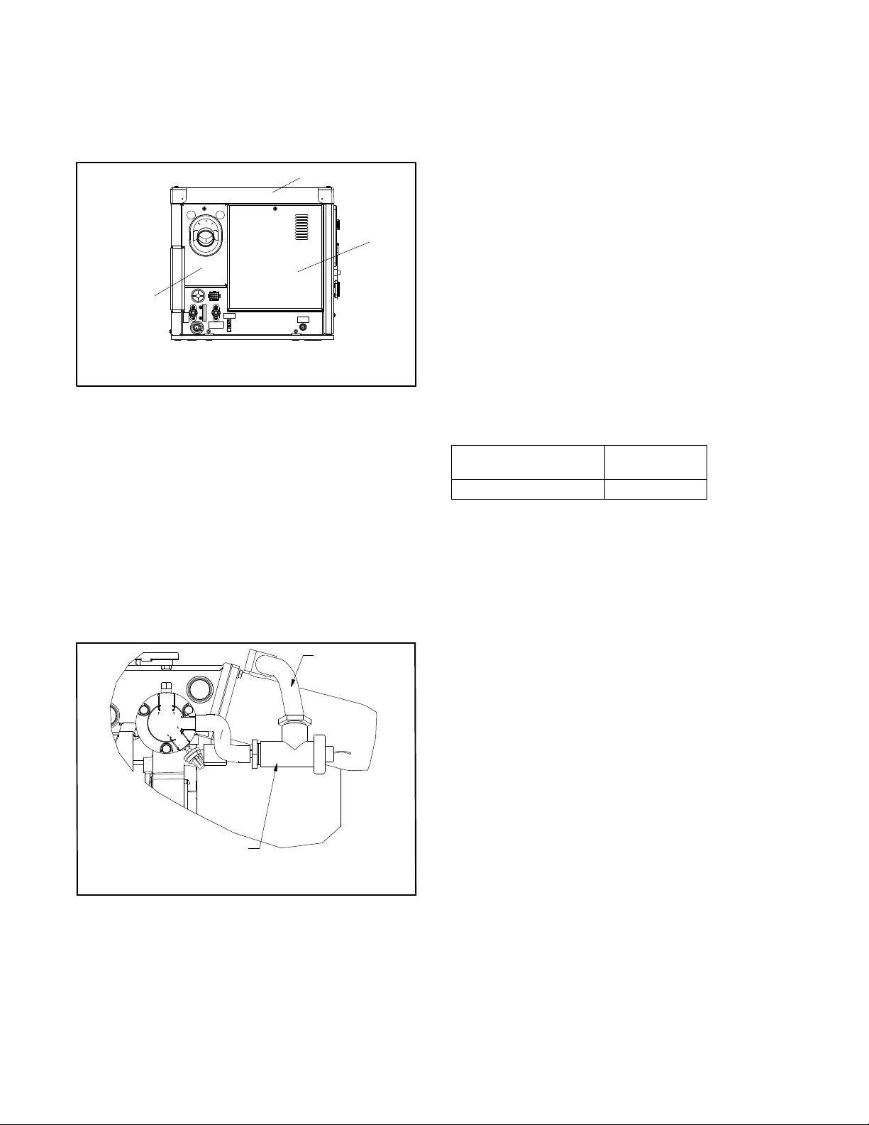
3.12 Connect the clear flexible plastic tubing
(GM34883) to the siphon break cap using a hose
clamp (X-426-9) to secure. Route the tubing to a
convenient location. This allows the seawater to
drip into the bilge and not on the generator set.
3.13 Siphon break mounting varies with each
application. Generally, use brass or stainless
steel screws and mount the siphon break using
the mounting tabs. Otherwise, use a nylon
(conduit-type) pipe clamp.
Note: Mount the siphon break in a location easily
accessable for inspection and servicing.
Note: Ensure that the siphon break cap is tight before
operating the generator set.
4. Restore the generator set to service.
4.1 Check that the generator set is OFF.
4.2 Reconnect the generator set engine starting
battery, the negative (--) lead last.
4.3 Reconnect the power to the battery charger, if
equipped.
4.4 Start the generator set and check for water leaks.
4.5 Stop the generator set.
4.6 Replace the sound shield’s exhaust panel, door,
and roof.
Inspection/Maintenance
Service the siphon break during regular exhaust system
component inspection. See the generator set operation
manual for the service schedule.
Note: The generator set must not be running during the
siphon break inspection.
1. Remove the generator set from service.
1.1 Press the start/stop button to stop the generator
set. The engine stops.
1.2 Press the power button to turn off the controller.
1.3 Disconnect the power to the battery charger, if
equipped.
1.4 Disconnect the generator set engine starting
battery, the negative (--) lead first.
2. Inspect the siphon break.
2.1 Remove the retaining cap and remove the reed
valve for inspection. See Figure 5.
2.2 Use a mild detergent to remove residue and
oxidation from the reed valve.
2.3 Clear blockage from the reed valve opening.
2.4 Replace the siphon break if the reed valve is
cracked or if the reed valve material has hardened
or deteriorated.
2.5 Install the reed valve into the mounting base with
the valve downward. See Figure 5, item 3.
2.6 Install and only finger tighten the retaining cap. Do
not overtighten it.
1. Cap
2. Siphon reed valve
3. Mounting base
1
2
3
Figure 5 Siphon Break
3. Restore the generator set to service.
3.1 Check that the generator set is OFF.
3.2 Reconnect the generator set engine starting
battery, the negative (--) lead last.
3.3 Reconnect the power to the battery charger, if
equipped.
Parts List
Siphon Break Kit
Kit: GM60007-KP1
Qty. Description Unique Parts
2Grommet, round X-284-7
1Hose, 0.63 in. ID (11.5 in.) X-312-16
1Hose, 0.63 in. ID (8.0 in.) X-312-61
2Clamp, hose (0.69/1.25 in.) X-426-12
1Valve, siphon break GM32985
2Connector, hose 344934
1Tubing, clear flexible plastic GM34883
1Clamp, hose (0.25/0.70 in.) X-426-9

4TT-1509 4/14
GM60007-A
Generator-End View
1. Hose connectors (344934 qty. 2)
2. Hose (X-312-16). Route the hose to the seawater flow switch
and use existing hose clamps. Remove molded hose. Cut
hose to fit for 5/7.5EKD and 4/6EFKD models.
3. Rotate the fittings on the exhaust catalyst.
4. Hose (X-312-61) and hose clamps (X-426-3 qty. 2). Cut hose
to fit for 5/7.5EKD and 4/6EFKD.
5. Grommets (X-284-7 qty. 2)
5
Top View
1
2
3
4
Service-Side View
Figure 6 Hose Locations
2
3
4
5
6
4
1
1. Exhaust panel
2. Hose connectors, qty. 2
3. Grommets, qty. 2
4. Customer-supplied hose clamps
5. Customer-supplied hoses
6. Siphon break valve
Figure 7 Siphon Break, Installed
KOHLER CO., Kohler, Wisconsin 53044 USA
Phone 920-457-4441, Fax 920-459-1646
For the nearest sales and service outlet in the
US and Canada, phone 1-800-544-2444
KOHLERPower.com
Kohler Power Systems
Asia Pacific Headquarters
7 Jurong Pier Road
Singapore 619159
Phone (65) 6264-6422, Fax (65) 6264-6455
Availability is subject to change without notice. Kohler Co. reserves the
right to change the design or specifications without notice and without any
obligation or liability whatsoever. Contact your local Kohlerrgenerator
set distributor for availability.
2009 and 2014 by Kohler Co. All rights reserved.
Other manuals for 5EKD
1
This manual suits for next models
5
Table of contents
Other Kohler Power Supply manuals
Popular Power Supply manuals by other brands

Oxford Instruments
Oxford Instruments NanoScience MercuryiPS Operator's manual

Altronix
Altronix Tango1B installation guide

artisan
artisan T800 Series Service manual

Chroma
Chroma 63610-80-20 Operation & programming manual

Viabizzuno
Viabizzuno n55 binario Installing instructions

Ebyte
Ebyte DM41-20W2412B1 user manual