Toa VX-3150DS User manual

OPERATING INSTRUCTIONS
POWER SUPPLY MANAGER VX-3150DS
Thank you for purchasing TOA’s Power Supply Manager.
Please carefully follow the instructions in this manual to ensure long, trouble-free use of your equipment.
1134
TOA Electronics Europe GmbH
Suederstrasse 282, 20537 Hamburg, Germany
1134-CPR-137
DoP 16-005
EN 54-4: 1997 + A1: 2002 + A2: 2006
Fire Detection and fire alarm systems - part 4: power supply equipment

2
TABLE OF CONTENTS
1. SAFETY PRECAUTIONS ............................................................................. 3
2. FEATURES ............................................................................................................ 4
3. NOMENCLATURE AND FUNCTIONS ................................................. 5
Front ............................................................................................................................. 5
Front (with the front panel removed) ............................................................................ 6
Rear ............................................................................................................................. 7
4. INSTALLATION .................................................................................................. 8
4.1. Installing the VX-3150DS in the Cabinet Rack ..................................................... 8
4.2. Battery Installation ............................................................................................... 8
4.3. Affixing Declaration of Compliance (EN 54-4 Standard) ................................... 12
5. CONNECTIONS ............................................................................................... 13
5.1. Connecting the VX-3150DS to VX-2000 System ................................................ 13
5.2. Connecting the VX-3150DS to SX-2000 System ............................................... 14
5.3. Connecting the VX-3150DS to VM-3000 System .............................................. 17
5.4. Connecting the VX-3150DS to VX-3000 System ............................................... 21
6. CABLE USAGE TABLE ............................................................................... 23
7. SWITCHING OFF SYSTEM POWER (DC) ....................................... 24
8. BLOCK DIAGRAM ......................................................................................... 25
9. APPENDIX: ........................................................................................................ 26
10. SPECIFICATIONS ........................................................................................ 31
Accessories ............................................................................................................... 31

3
1. SAFETY PRECAUTIONS
• Before installation or use, be sure to carefully read all the instructions in this section for correct and safe
operation.
• Be sure to follow all the precautionary instructions in this section, which contain important warnings and/or
cautions regarding safety.
• After reading, keep this manual handy for future reference.
Safety Symbol and Message Conventions
Safety symbols and messages described below are used in this manual to prevent bodily injury and property
damage which could result from mishandling. Before operating your product, read this manual rst and
understand the safety symbols and messages so you are thoroughly aware of the potential safety hazards.
Indicates a potentially hazardous situation which, if mishandled, could
result in death or serious personal injury.
Indicates a potentially hazardous situation which, if mishandled, could
result in moderate or minor personal injury, and/or property damage.
WARNING
CAUTION
When Installing the Unit
• Do not expose the unit to rain or an environment
where it may be splashed by water or other liquids,
as doing so may result in re or electric shock.
• Use the unit only with the voltage specied on
the unit. Using a voltage higher than that which is
specied may result in re or electric shock.
• Do not cut, kink, otherwise damage nor modify
the power supply cord. In addition, avoid using the
power cord in close proximity to heaters, and never
place heavy objects -- including the unit itself -- on
the power cord, as doing so may result in re or
electric shock.
When the Unit is in Use
• Should the following irregularity be found during
use, immediately remove the AC power plugs (AC
power cords), disconnect the battery, and contact
your nearest TOA dealer. Make no further attempt
to operate the unit in this condition as this may
cause re or electric shock.
· If you detect smoke or a strange smell coming
from the unit.
· If water or any metallic object gets into the unit
· If the unit falls, or the unit case breaks
· If the power supply cord is damaged (exposure of
the core, disconnection, etc.)
· If it is malfunctioning (no tone sounds.)
• To prevent a re or electric shock, never open the
unit case nor modify the unit. Refer all servicing to
qualied service personnel.
• Do not place cups, bowls, or other containers of
liquid or metallic objects on top of the unit. If they
accidentally spill into the unit, this may cause a re
or electric shock.
• Do not insert nor drop metallic objects or ammable
materials in the ventilation slots of the unit’s cover
as this may result in re or electric shock.
• Do not touch a power supply plug during thunder
and lightning, as this may result in electric shock.
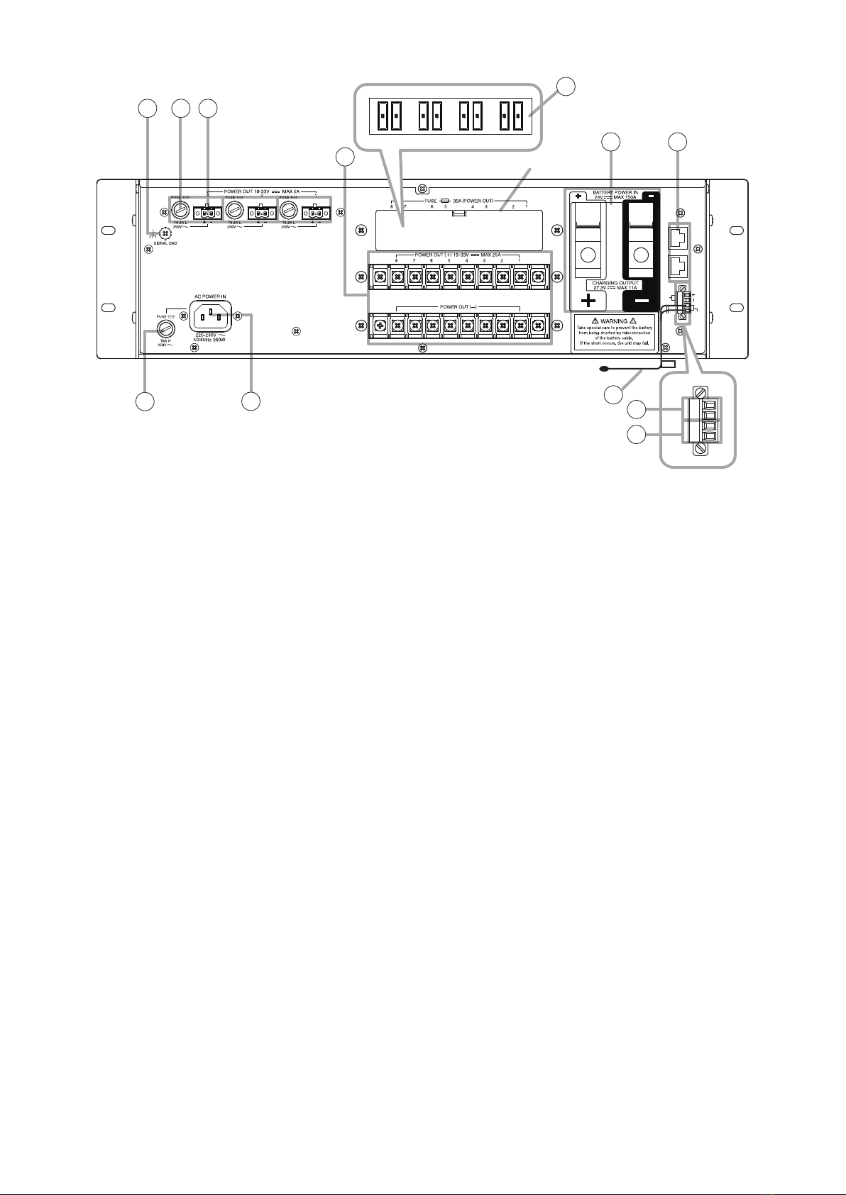
•
When replacing the AC or DC fuse, be sure to use the
proper one among the following supplied fuses: AC
fuse T8A H, AC fuse T6.3A L, and Blade fuse 35 A.
Using any other fuse than supplied may cause re or
electric shock.
• Handle or use the batteries properly.
Doing otherwise may cause leakage or explosion
of the batteries, resulting in a re, personal injury,
damage to peripheral equipment, or contamination
of environment.
When Installing the Unit
•
Never plug in nor remove the power supply plug with
wet hands, as doing so may cause electric shock.
• When unplugging the power supply cord, be sure to
grasp the power supply plug; never pull on the cord
itself. Operating the unit with a damaged power
supply cord may cause a re or electric shock.
• Do not block the ventilation slots in the unit’s cover.
Doing so may cause heat to build up inside the unit
and result in re.
WARNING
CAUTION

4
• When connecting multiple appliances to a single
power socket through a multi-outlet power strip, a
total current consumption of the appliances must
not exceed the allowable current capacity of the
power socket.
Failure to observe this instruction may result in a
re or electric shock.
• When 2 or more AC power cords are connected to
a multi-outlet power strip, never remove the power
strip from a power source.
• Avoid installing the unit in humid or dusty locations,
in locations exposed to the direct sunlight, near the
heaters, or in locations generating sooty smoke
or steam as doing otherwise may result in re or
electric shock.
• System units (except remote microphones) are
designed exclusively to be mounted in an equipment
rack. Be sure observe the following instructions
when rack-mounting the unit. Failure to do so may
cause a re or personal injury.
· Install the equipment rack on a stable, hard oor.
Fix it with anchor bolts or take other arrangements
to prevent it from falling down.
· The supplied rack-mounting screws can be used
for the TOA equipment rack only. Do not use them
for other racks.
• Note correct polarity (positive and negative
orientation) when connecting the power supply
cord. Reversed polarity connections will cause
damage to the system.
When the Unit is in Use
• Use the specied power supply unit for the system.
Note that the use of other power supply unit may
cause a re.
• Make sure to observe the following handling
precautions so that a re or personal injury does
not result from leakage or explosion of the battery.
· Do not short, disassemble, heat nor put the battery
into a re.
· Avoid using both new and old batteries together.
· Never charge batteries of the type which are not
rechargeable.
· Do not solder a battery directly.
· Be sure to use the specied type of batteries.
· Note correct polarity (positive and negative
orientation) when connecting a battery to the unit.
· Avoid locations exposed to the direct sunlight,
high temperature and high humidity when storing
batteries.
2. FEATURES
• Automatically switches to the backup power supply when the AC Mains power supply is interrupted.
• Detects charging circuitry or battery failures, and transmits failure signals to the DS LINK of the TOA Voice
Evacuation Systems (VX-2000, SX-2000, VM-3000, and VX-3000).
• Keeps a 2 x 12 V sealed lead-acid battery charged while maintaining temperature compensation for the
charging voltage.
• Automatically disconnects the battery if its voltage reaches a discharge nal level.

5
3. NOMENCLATURE AND FUNCTIONS
[Front]
12 3
4 5 6
AC POWER BATTERY
IN POWER
CONNECT
CONDITION
POWER SUPPLY MANAGER VX-3150DS
CHECK
CHARGING
1. Power indicators [AC POWER IN]
Light green when AC power is supplied through the
AC inlet (18).
2. Battery connection indicator
[BATTERY CONNECT]
Lights green when the battery is connected.
3. Battery indicator [BATTERY POWER]
Indicates the state of battery usage. Lights green
when the AC power supply is interrupted and
switched over to the backup batteries.
4. Charging indicator [CHARGING]
Indicates battery charging status. Flashes green
while charging, and continuously lights green after
charging completion.
5. Battery check button [BATTERY CHECK]
Pressing this button permits the internal resistance
measurement of the backup batteries and also the
operation check of the built-in 2 fans.
The Battery check indicator goes off if the measured
resistance exceeds the specied value.
In automatic mode, the unit performs battery check
every 3 and a half hours.
When the DS LINK is connected to the VX-2000
system, SX-2000 system, VM-3000 system, or
VX-3000 system, the resistance measurement is
activated by the equipment, not by the unit itself.
Note
Battery check cannot function for 1 minute during
of which Battery indicator (3) ashes twice, pause,
and then repeats after it has been activated once.
In this case, wait a few minutes, then reactivate it.
6. Battery check indicator [BATTERY CONDITION]
In the AC operated system, the internal resistance
value of the battery is measured automatically or
manually to check whether the battery is faulty.
The Battery check indicator indicates the result.
• Before measurement:
Flashes green at 2-second intervals.
• During measurement:
Flashes green at 1-second intervals.
• Normal: Lights green.
• Abnormal: Remains unlit.
In the battery-operated system, the battery voltage
is constantly monitored and its level is indicated by
the indicator as shown below without pressing the
Battery check button.
• Lights green: 25 V or more
• Flashes green: 20 – 25 V
• OFF: 20 V or less

6
[Fault indication]
If any of the following indicators on the front panel remains unlit, the unit is judged failed. In such cases, remove
the cause of the failure, and restore the unit to normal operation.
• Power indicator [AC POWER IN]
• Battery connection indicator [BATTERY CONNECT]
• Charging indicator [CHARGING]
• Battery check indicator [BATTERY CONDITION]
Note
Even if any of these indicators ashes, this does not indicate malfunction.
[Front (with the front panel removed)]
9
78
7. DIP switch
81
ON
OFF
• Switches 1 and 2 are not used.
Be sure to leave both switches OFF.
• Switches 3 – 8 are factory-preset as shown below.
Switches 3 and 5: ON
Switches 4 and 6 – 8: OFF
Each switch function is described as follows.
Switch 3
Used for terminating the connection.
Set to ON when no other VX-3150DS unit is
connected or when this unit is the last one of
connected units.
Switches 4 and 5
Set the upper limit value of the internal battery
resistance and battery connection cable resistance
to be monitored for fault detection.
Setting switch combination of 4 and 5 is as follows.
5
ON OFF
4ON 25 mΩ 100 mΩ
OFF 50 mΩ* DISABLE
* Settings compliant with EN 54-4.
Switch 6
Sets the battery charging current.
ON: N/A
OFF: 5.5 A*
* Settings compliant with EN 54-4.
Switch 7
ON: N/A
OFF: Failure detection function enabled.*
Set to OFF when using AC Power IN.
* Settings compliant with EN 54-4.
Switch 8
Places the unit in AC operation mode or battery
mode.
ON: All power outputs are shut down when AC
power fails even if backup batteries are
connected. (AC operation mode).
OFF: Battery is used as backup power supply
when AC power fails. (Battery mode)
Be sure to set to OFF in normal operation.
8. Shutdown button
Pressing this button forcibly shuts down this unit
irrespective of Switch 8 ON/OFF setting of the DIP
switch (7).
9. Reset button
Pressing this button resets this unit.

7
[Rear]
10. Functional earth terminal [SIGNAL GND]
Hum noise may be generated when external
equipment is connected to the unit. Connecting
this terminal to the functional earth terminal of the
external equipment may reduce the hum noise.
Note: This terminal is not for protective earth.
11. Fuse holders
Requires an AC fuse.
Ratings: 250 V, T6.3A L
12. DC output terminals
[POWER OUT 19-33V MAX 5A]
DC 33 V max., 5 A max.
Supply DC power to the SX-2000SM or VX-2000
or other DC-operated devices except power
ampliers.
13. DC output terminal
[POWER OUT 19-33V MAX 25A]
DC 33 V max., 25 A max.
Supplies DC power to power ampliers or other
DC-operated devices.
14. Fuses
Provided in each DC output.
Type and rating: Blade-Type Fuse 35 A
Remove the protection cover when replacing the fuse.
15. Battery connection terminal
[BATTERY POWER IN]
Connects to the backup sealed lead-acid battery.
Recommended battery:
2 x Panasonic LC-X1265PG/APG
2 x Panasonic LC-XA12100P
2 x Panasonic LC-XB12100P*
2 x Yuasa NP65-12
2 x Yuasa NPL100-12
* Compliant with EN54-4
16. Control connectors [DS LINK IN, OUT]
• DS LINK IN connector
Connects to DS LINK connector of the VX-2000
system, SX-2000 system, VM-3000 system, or
VX-3000 system.
• DS LINK OUT connector
Connects to DS LINK IN connector of a daisy-
chained unit.
Note: This connection is required only when 2
to 4 units are connected to one DS LINK
connector.
17. Fuse holders
The specied AC fuses are incorporated.
Ratings: 250 V, T8A H
18. AC inlet (AC POWER IN)
Connect to power source of 220 - 230 V AC, 50/60
Hz using the supplied power cords.
Connect both AC POWER IN to AC mains power
outlet from single circuit breaker line.
19. DC output terminal
[POWER OUT 24V(16-25V) MAX 0.3A]
DC 24 V max., 0.3 A max.
Supplies DC power to the DC-operated devices
except power ampliers.
20. Temperature sensor connection terminal
[TEMPERATURE SENSOR]
Detects the ambient temperature of the backup
battery, and performs temperature compensation
for the charging voltage. For the installation
instructions, refer to p. 11.
The temperature sensor has a serial number label
attached to it.
When connecting the temperature sensor to this
terminal, conrm the serial number matches that
of the VX-3150DS.
10
16
Protection cover
12
17
15
13
11
18
TEMPERATURE
SENSOR
24V(16-25V)
POWER OUT
MAX 0.3A
IN
OUT
DS LINK
View with the cover removed
14
20
19
20

8
4. INSTALLATION
4.1. Installing the VX-3150DS in the Cabinet Rack
4.2. Battery Installation
• Take special care to prevent the battery from being shorted by misconnection of the battery cable.
If the short occurs, the unit may fail.
Follow the instructions in this section for safe and secure connection.
• Be sure to switch off the system power before battery connection. For the procedure, refer to p. 24
“SWITCHING OFF SYSTEM POWER (DC).”
• After completing the battery connection, be sure to attach a terminal cover onto each battery terminal
to prevent shorts between positive and negative terminals.
[Cable end treatment]
To secure the connection between the battery terminal and cable, be sure to use the cable of specied diameter
and treat its end as follows.
Usable cable diameter: AWG 6 – AWG 0 (AWG 1/0)
(Line resistance should be within 4 mΩ in total.)
Stripped length: 30 mm ± 5 mm
Cross sectional area: 16 – 50 mm2
[Cautions on cable connection to the battery terminal]
• Before connecting the battery cable to the battery
terminal, be sure to fully open the cable clamp by turning
the terminal screw counterclockwise.
Battery terminal Terminal screw
Cable clamp
Fully open. Too narrow to
clamp the cable
Incorrect
Rack mounting screw
5 x 12
WARNING

9
• Strip the cable end long enough (30 mm ± 5 mm) to be
fully clamped. Otherwise, its outer jacket prevents the
cable conductor from being tightly secured, causing poor
contact.
[Connecting the battery]
Note correct polarity (positive and negative orientation) when connecting
the power supply cord. Reversed polarity connections will cause damage
to the system.
• Insert the battery cable into the correct position in the battery terminal referring to the terminal's cross sectional
diagrams below.
18 kΩ (1/4 W)
Battery Battery
Notes
To avoid battery failure and charger failure, take care of the following points.
• If batteries not recommended by the manufacturer are used and a charger failure occurs, connect a resistor
of 18 kΩ (1/4 W) parallel to the batteries.
• Use the specified type of batteries and capacity.
• When batteries are connected together in a series-parallel arrangement, the inter-connecting cables must be
of equal length and resistance to insure equalization of the load.
• Do not mix batteries with different capacity, new and old batteries, or batteries of different manufacturers.
Doing so may cause different characteristic values among batteries, possibly resulting in damage to the
batteries themselves or the connected equipment.
CAUTION
Correct position of the cable insertion Incorrect position of the cable insertion
Wrong insertion position of the cable or a forked
cable insertion causes poor contact or insufcient
connection tightness, making the cable come off to
possibly cause short-circuit accident.
4.2.1. Correct 4.2.2. Incorrect
Cable conductor
Cable clamp

10
Step 1. Allow more than 10 seconds to elapse after removing the power cords from the VX-3150DS' rear-
mounted AC inlet.
Step 2. Insert the positive battery cable into the VX-3150DS' rear-mounted BATTERY POWER IN positive
terminal from the bottom side of the connector, then tighten the terminal screw with a at screwdriver.
Note
Never connect the negative cable rst to avoid battery short-circuit that occurs if the positive cable
should contact the unit chassis or equipment rack.
Step 3. Connect the negative battery cable to the negative terminal in the same manner as Step 2.
VX-3150DS Tightening torque: 6 – 8 Nm
3
2
Cable cross
sectional area
16 mm2
25 mm2
35 mm2
50 mm2
180 cm
280 cm
400 cm
570 cm
AWG 6
AWG 4
AWG 2
AWG 0 (AWG 1/0)
80 cm each
130 cm each
190 cm each
275 cm each
20 cm
20 cm
20 cm
20 cm
Length (2 mΩ)AWG Example of wire length
Cable A, Cable C Cable B
VX-3150DS’ Battery connection terminals
Battery terminals
6 – 8 Nm
4.1 – 5.6 Nm (M6)
8.2 – 5.6 Nm (M8)
• Use the battery connection cables as short in length and as large in diameter as possible.
Battery connnection terminals
Battery
Cable A Cable C
Cable B
Battery
VX-3150DS
TEMPERATURE
SENSOR
24V(16-25V)
POWER OUT
MAX 0.3A
IN
OUT
DS LINK
• Total resistance of the battery connection path should be less than 4 mΩ, which includes resistance of all of
wire, terminal, fuse, and terminal points.
For reference, refer to each resistance as follows.
Resistance of terminal, fuse (if provided): 1 – 2 mΩ
Resistance of terminal point: 0.1 – 0.5 mΩ
• Tighten the bolts, nuts, and screws of the unit's battery connection terminals and battery terminals with the
torque as shown below.

11
Step 1. Conrm that battery power is not in use by means of the VX-3150DS' front-mounted BATTERY POWER
LED, which is unlit in this case.
Step 2. Loosen the VX-3150DS' BATTERY POWER IN negative terminal screw, then pull out the negative
battery cable.
Notes
• Never remove the positive cable rst to avoid battery short-circuit that occurs if the positive cable
should contact the unit chassis or equipment rack.
• Insulate the exposed end of the removed cable with insulating tape to avoid shorting to the other cable.
Step 3. Remove the positive battery cable from the positive terminal in the same manner as Step 2.
Note
Insulate the exposed end of removed cable with insulating tape to avoid shorting to the other cable.
[Disconnecting the battery]
[Installing a temperature sensor]
The temperature sensor located on the VX-3150DS' rear panel is designed to compensate for temperature
changes when charging the battery. It should be mounted on the side of one battery in between 2 batteries
using the supplied thermal insulating sheet to avoid ambient temperature change, thereby maintaining the
temperature of the temperature sensor relatively constant.
For details about battery installation, refer to "9. APPENDIX: Recommendations to the Power
Supply Installation" on p. 26.
Reduced
side-view
Reduced
side-view
Thermal insulating sheet
(supplied with the VX-3150DS)
Attach to
the side
of battery
Temperature sensor mounting
Temperature sensor
mounting appearance
Temperature sensor
mounting appearance
Confirm both serial
numbers are the same.
(Horizontal installation of batteries)
(Vertical installation of batteries)
Step 1. Clean the exterior surface of the battery using a soft damp cloth.
Note: Avoid using chemical cleaners and solvents that may cause the battery cases to clack or leak.
Step 2. Follow the procedure shown above to attach the temperature sensor to the battery.
Note: The thermal insulating sheet is hard to remove after attached.

12
[Fixing the battery]
To comply with EN54-4, x the battery at the bottom plate surface of the rack as shown below.
Attach hook fasteners to the bottom or side surface of each battery, and loop fasteners to the bottom plate
surface of the rack.
Example when the hook fasteners are attached to the battery's bottom surface
4.3. Affixing Declaration of Compliance (EN 54-4 Standard)
To declare that the VX-3150DS complies with EN 54-4, afx the sticker supplied with the VX-3150DS visible to
the front panel of the equipment (e.g. at the upper right side as shown below).
EN54-4
VX-3150DS
Rack
AC POWER BATTERY
IN POWER
CONNECT
CONDITION
CHECK
CHARGING
EN 54-4
Sticker (supplied with the VX-3150DS)
Affix only the upper part of the
sticker to the equipment rack.
Paste this sticker on the outside
of the cabinet rack containing
the so certified equipment.
Hook fasteners
(supplied with the VX-3150DS)
Bottom of battery
135-01-075-2
135-01-076-3
VX-2000DS FASTENER HOOK (A)
VX-2000DS FASTENER LOOP (B)
131-27-891-2 VX-2000DS THERMAL INSULATING SHEET
Part code Part name
When replacing the batteries, 4 each of fastener hooks and loops, and a thermal insulating sheet listed
below are also required. Consult your nearest TOA dealer on how you can obtain them.

13
5. CONNECTIONS
5.1. Connecting the VX-3150DS to VX-2000 System
* Ferrite Cable Clamp Attachment (For VX-2000 only)
To reduce electromagnetic noise, place the supplied ferrite cable
clamp over the DC power cable at a position within 20 cm from the
VX-2000's DC POWER IN terminal.
DC POWER IN
DS-SF
LINK
1
2
28 V 4.8 A
DC POWER IN CH3 CH1
CH4 CH2
PA OUT (SP LINE)
C H
CH1
C H
CH2
C H
CH3
C H
CH4
DATA LINK
DC POWER IN
AUDIO LINK
OUT
DC POWER IN
FUSE 35A (POWER OUT)
BATTERY POWER IN
24V MAX 150A
POWER OUT(
-
)
1234567
POWER OUT(+) 19-33V MAX 25A
WARNING
Take special care to prevent the battery
from being shorted by misconnection
of the battery cable.
If the shore occurs, the unit may fail.
OUT
DS LINK
24V(16-25V) MAX 0.3A
POWER OUT
TEMPERATURE
SENSOR
8
IN
(–)
(+)
(–)
(+)
RJ45 male connector
VX-2000SF
VX-2000
VP-2000 series or VP-3000 series power amplifier
VX-3150DS
This figure shows VP-2000 series.
This figure shows VP-3000 series.
From VX-3150DS
From VX-3150DS
230 V AC
220 V AC
50/60 Hz
To “DS LINK IN” of
the next VX-3150DS
a
Ferrite cable clamp*
i ag ce
j bh df
i g ce j h df
12
b
(–)
(+)
Cat. 5 STP

14
5.2. Connecting the VX-3150DS to SX-2000 System
5.2.1. When using a redundant power system*
In this connection example, 2 power supply units are used. Even if one of the 2 units fails or its power supply
line is broken, power is still supplied from the other unit, preventing the system from going down.
* A method of connecting separate power sources to each power input or connecting the commercial power
supply and backup power supply separately to each power input to prevent the system from going down when
a cable is broken or power fails.
Note
For DC power supply to each component, it is possible to use either of "POWER OUT 19 – 33 V MAX 5 A"
terminal or "POWER OUT 19 – 33 V MAX 25 A" terminal.
SX-2100AI
SX-2100AO or SX-2000AO
(The figure below shows the SX-2100AO.)
Cable: AWG 18 – AWG 14
VX-3150DS
VX-3150DS
4P removable terminal plug
(supplied with the SX-2000SM, SX-2100AI, SX-2000AO
SX-2100AO, SX-2000CI, and SX-2000CO)
SX-2000SM
SX-2000CI
SX-2000CO
(DC power input terminal)
Power line BPower line B
Power line APower line A
(DC power input terminal)
230 V AC
220 V AC
50/60 Hz
230 V AC
220 V AC
50/60 Hz
+
–
+
–
TEMPERATURE
SENSOR
24V(16-25V)
POWER OUT
MAX 0.3A
IN
OUT
DS LINK
TEMPERATURE
SENSOR
24V(16-25V)
POWER OUT
MAX 0.3A
IN
OUT
DS LINK
+
-
+
-

15
5.2.2. When not using a redundant power system
Required power is supplied to the system from a single power supply unit. Connect the [+] terminal of Input A to
the [+] terminal of Input B, and the [–] terminal of Input A to the [–] terminal of Input B.
Note
To supply DC power to each component such as SX-2100AO and SX-2000SM except power ampliers, the
VX-3150DS’ “POWER OUT 19 – 33 V MAX 25 A” terminal can also be used.
28 V 4.8A
DC POWER IN CH3 CH1
CH4 CH2
PA OUT (SP LINE)
C H
CH1
C H
CH2
C H
CH3
C H
CH4
28 V 4.8 A
DC POWER IN
FUSE 35A (POWER OUT)
BATTERY POWER IN
24V MAX 150A
POWER OUT(
-
)
1234567
POWER OUT(+) 19-33V MAX 25A
WARNING
Take special care to prevent the battery
from being shorted by misconnection
of the battery cable.
If the shore occurs, the unit may fail.
OUT
DS LINK
16-24V MAX 0.3A
POWER OUT
TEMPERATURE
SENSOR
8
IN
CH4 CH3 CH2 CH1 CH4 CH3 CH2 CH1
h g ef
d c ab
FUSE
250V
2 1
T6.3A L
POWER OUT(
-
)
POWER OUT(+) 19 – 30V MAX 25A
d c ab
h g ef
VX-3150DS
4P removable terminal plug
(supplied with the SX-2000SM, SX-2100AI, SX-2000AO,
SX-2100AO, SX-2000CI, and SX-2000CO)
(DC power input terminal) (DC power input terminal)
SX-2100AI
SX-2100AO or SX-2000AO
(The figure below shows the SX-2100AO.)
SX-2000SM
SX-2000CI
SX-2000CO
+
+
-
-
-
VP-2064, VP-2122, VP-2241, or VP-2421
VP-3154, VP-3304, or VP-3504 x 2 CH*
230 V AC
220 V AC
50/60 Hz
Cable: AWG 18 – AWG 14
+
* VP-3504 x 2 CH: That only 2 channels can be used when VP-3504 connect to VX-3150DS.

16
[Cable termination]
When connecting 2 power cables to a single terminal of the removable
terminal plug, use a ferrule terminal with an insulation sleeve to crimp the
cables because such cable conductors could become loose.
Recommended "Phoenix Contact" ferrule terminals for power supply
cables
Crimping tool: CRIMPFOX UD6-4 (made by Phoenix Contact)
a
l2
a1
a2
l1
l2
l1
bb
Insulation sleeve
Contact section
Insulation sleeve
Contact section
5.2.3. DS LINK terminal connections
Connect the DS LINK terminal of the VX-3150DS to the DS Link terminal of the SX-2000SM or SX-2100AO. The
figure below shows a connection example when the VX-3150DS units are connected to the SX-2100AO. This
connection also applies to the SX-2000SM.
Model Number a1l1l2
AI 1,5-8 BK
AI-TWIN 2x1,5-8 BK 6.6 mm
a2
3.6 mm
14 mm
16 mm2.3 mm
8 mm
8 mm
a
3.4 mm
b
1.8 mm
TEMPERATURE
SENSOR
24V(16-25V)
POWER OUT
MAX 0.3A
IN
OUT
DS LINK
TEMPERATURE
SENSOR
24V(16-25V)
POWER OUT
MAX 0.3A
IN
OUT
DS LINK
DS LINK
INOUT
DS LINK
INOUT
SX-2100AO
VX-3150DS (No. 1)
VX-3150DS (No. 2)
230 V AC
220 V AC
50/60 Hz
230 V AC
220 V AC
50/60 Hz
Cat. 5
STP

17
5.3. Connecting the VX-3150DS to VM-3000 System
VX-3150DS
VP-2241
PA LINK VP-200VX
28 V 4.8 A
DC POWER IN
PA OUT (SP LINE)
C H
TEMPERATURE
SENSOR
24V(16-25V)
POWER OUT
MAX 0.3A
IN
OUT
DS LINK
RJ45 male connector
AWG 6 – AWG 0 (1/0)
VM-3240VA/3360VA
From
VX-3150DS
From VX-3150DS
From VX-3150DS
Note
Remove the short bar attached at the factory.
230 V AC
220 V AC
50/60 Hz
230 V AC
220 V AC
50/60 Hz
230 V AC
220 V AC
50/60 Hz
Lead-acid Battery
(–)
(+)
+
VP-3000 series power amplifier
VM-3240E/3360E
-
+
-
Cat.5
STP
a
ef
c
d
b
(–)
(+)
From
VX-3150DS
m k gi n l hj
ikm ag ce
jln bh df
(–)
(+)

18
5.3.1. Required number of VX-3150DS units in a 1-channel broadcasting system
The required number of the VX-3150DS Power Supply Manager units is determined depending on the application
of the system congured with the VM-3240VA, VM-3360VA, VM-3240E, and VM-3360E (hereinafter called "VM
amplier"), and/or the VP-2241, VP-2421, VP-3304, and VP-3504 x 2 CH* (hereinafter called "VP amplier").
[System including VM amplifiers only]
One VX-3150DS is required every 2 VM-3360VA/3360E ampliers or 3 VM-3240VA/3240E ampliers.
Below is an example showing that one VX-3150DS is used in a system including 3 VM ampliers.
No. of VM-3360VA/3360E 1 2345678910
No. of VX-3150DS units 1 2345
No. of VM-3240VA/3240E 1 2345678910
No. of VX-3150DS units 1 2 3 4
VM LINK
DC POWER
DS LINK
VM-3240VA
VM-3240E
VM-3240E
Lead-acid Battery
VX-3150DS VM LINK
* VP-3504 x 2 CH: That only 2 channels can be used when VP-3504 connect to VX-3150DS.

19
[System including one VP amplifier connected as a standby amplifier]
One VX-3150DS is required every 2 VM-3360VA/3360E ampliers or 3 VM-3240VA/3240E ampliers.
Below is an example showing that one VX-3150DS unit is used in a system including 3 VM ampliers.
No. of VM-3360VA/3360E 1 2345678910
No. of VX-3150DS units 1 2345
No. of VM-3240VA/3240E 1 2345678910
No. of VX-3150DS units 1 2 3 4
* VP-3504 x 2 CH: That only 2 channels can be used when VP-3504 connect to VX-3150DS.
VM-3240VA
VX-3150DS
VP-3304, VP-2241,
or VP-3504 x 2 CH*
EXT. AMP INPUT
EXT. PA LINK
DC POWER
VM LINK
DC POWER
DS LINK
PA OUT
PA OUT
VM-3240E
VM-3240E
EXT. AMP
INPUT
EXT. AMP
INPUT
VM LINK
Lead-acid Battery

20
Below is an example showing that 2 VX-3150DS units are used in a system including 5 VM-3240VA/3240E ampliers.
[Required number of VX-3150DS units in a BGM/Paging system]
One VX-3150DS is required every 2 VM-3360VA/3360E ampliers or 3 VM-3240VA/3240E ampliers.
Note
A pair of the VM amplier and VP amplier should be connected to the same VX-3150DS.
No. of VM-3360VA/3360E 1 2345678910
No. of VX-3150DS units 1 2345
No. of VM-3240VA/3240E 1 2345678910
No. of VX-3150DS units 1 2 3 4
* VP-3504 x 2CH: That only 2 channels can be used when VP-3504 connect to VX-3150DS.
VM-3240E
VM-3240E
VM-3240VA
EXT. AMP INPUT
EXT. PA LINK
DC POWER
VM LINK
DC POWER
DS LINK
DC POWER
DS LINK
VM LINK
PA OUT
EXT. AMP INPUT
EXT. PA LINK
PA OUT
EXT. AMP INPUT
EXT. PA LINK PA OUT
DC POWER
DC POWER
VX-3150DS
VX-3150DS
No.4
No.1
Lead-acid Battery
Lead-acid Battery
No.5
VP-3304, VP-2241,
or VP-3504 x 2 CH*
VP-3304, VP-2241,
or VP-3504 x 2 CH*
VP-3304, VP-2241,
or VP-3504 x 2 CH*
Table of contents
Other Toa Power Supply manuals