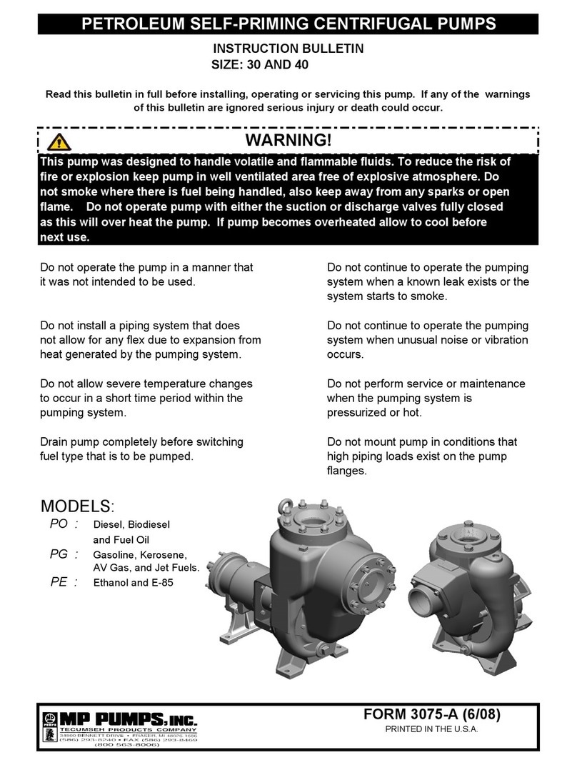
MP PUMPS FLOMAX 40 Series Training manual

Instruction Bulletin
Series 300, 700, and FLOMAX 40 PUMPS
MOUNTING THE PUMP - Close-coupled
pumps are assembled into a rigid unit and
should be bolted down securely. The close-
coupled pump can be mounted in any posi-
tion. However, when mounted in other than
horizontal position, the pump motor must be
located above the pump so that liquid leak-
age will not damage the motor.
Pedestal or foot mounted pumps with grease
lubricated bearings can be mounted in any po-
sition. The bearing housing must be above
the pump in any non-horizontal application to
preventbearingdamageduetoliquidleakage.
The pedestal or foot mounted pumps, when
provided with driver and a coupling, are
mounted on a steel base plate which accom-
modates both pump and driver. Although the
components have been aligned accurately
at the factory, the alignment must be re-
checked after the unit has been set in place
at the job site.
PIPING - Do not allow the pump to carry the
weight of piping. Both suction and discharge
piping should be supported independently at
apointnearthepump.Pipingmustbeinstalled
carefullyso that it will notbenecessary to force
it into place when connecting to the pump.
Useslip jointsorflexibleconnectors wherelong
discharge lines are being used or lines that
are subject to wide temperature ranges. Flex-
ible connectors also help to prevent transmis-
sion of noise and vibrations.
SUCTION PIPING - Place pump as close to
the liquid source as possible. The suction line
should be short, and large, with as few fittings
as possible and with smooth long radius el-
bows, where space permits, to keep friction
loss at a minimum. When necessary, a good
strainer or foot valve for priming should be
used. A valve is usually included in the suc-
tion line to facilitate servicing the pump. Suc-
tion piping must be absolutely free of leaks.
Also a careful check must be made to be sure
that the pump’s required net positive suction
head (NPSHR) is available. When the suction
line draws liquid from an open sump, its lower
end should be submerged sufficiently so that air
is not drawn into the line by vortex action.
If a reducer is used between piping and pump,
reducershould be eccentric typewiththe flat side
on top to prevent air from being trapped in the
suction line. Piping should always slope up to
the pump with no high spots to trap air.
DISCHARGE PIPING - To minimize friction
losses, care should be taken in sizing, layout,
number of fittings, etc. of discharge pipeline. A
gate valve should be installed in discharge line
to control pump flow and to allow servicing of
pump without having to drain the discharge line
andany connected vessels. Thedischargevalve
should be open during self-priming start-up for
the FLOMAX 40.
START UP:
Centrifugal pumps must be primed before they
will start pumping. Fill the suction line and pump
and enough of the discharge line to establish a
liquid level one or two feet above the top of the
pump case. Turn the pump shaft by hand so
that air trapped within the immpeller can escape.
The FLOMAX 40 is a self-priming pump. The
pump case must be filled with water for initial
start-up. The suction line of this pump does not
have to be filled as the pump will evacuate the
air from the line when it performs its self-priming
function.
Make sure that the gate valve between the suc-
tionof the pumpandthe sourceofsupply is open.
FORM 3021-D (10/04)
1

IMPORTANT:
Check for correct direction of rotation of
prime-mover. Check rotation of three phase
motors by turning on power only for an instant
so that pump turns just a few revolutions (pro-
longed operation of pump in wrong direction may
damage it). If direction is wrong, reverse rotation
by interchanging any two of the three wires, ei-
ther at the motor or electric starter, in a threephase
electrical system.
Close gate valve in discharge line and start pump.
Open valve gradually to half-open position after driver
attains full speed. If pump fails to function after a few
seconds of operation, stop it, add more priming liquid
if needed, and let air escape completely. Restart the
pump.
FLOMAX 40, as a self-priming pump, requires that
the discharge valve be in the fully open position on
start-up to permit the air in the suction line to be ex-
pelled into the discharge line. Failure to open the dis-
charge line will prohibit the pump from priming itself.
Self-priming requires a minute or more for the pump
to evacuate the air from the suction before pumping
begins.
Do not permit the pump to run for more than a few
secondsunlessit remains full of liquidandis discharg-
ing properly. Prolonged operation of an unprimed
pump can cause severe damage to rotating parts.
If the pump must be shut down after initial start up
while exposed to below freezing weather, protect it
and connected piping from damage by draining the
system completely or by introducing a corrosion in-
hibiting antifreeze to the system.
SERVICE AND MAINTENANCE INSTRUCTIONS
When seal maintenance is required, they can be ser-
viced by leaving the housing in the piping. All pumps
have back pull out design. Jackscrews are provided
to assist in removing the housing and seal cover.
NOTE:
Alifting eye is provided to lift the pump only. This
should not be used to lift the electric motor, base,
and pump assembly.
Thefollowinginstructionsassumetheentirepump has
been removed from the piping and is on a bench to be
serviced. The instructions for back pullout are the
same with the exception that the two bolts holding the
bearing assembly to the rear support bracket should
be removed allowing the bearing adaptor, impeller,
and shaft assembly to be removed in the back pullout
mode. Refer to proper parts list.
There are two possible causes for leaks along the pump
shaft:
1. The impeller sealing gaskets could be worn or de-
fective causing leakage through the sleeve.(See Fig-
ure1). When the pump is operating this leakage can
be detected by visual inspection of the juncture be-
tween sleeve and the shoulder on the pump shaft.
2. A worn or defective seal. In most cases, a seal
leak will be a much higher capacity leak than that
of a leak underneath the sleeve. In addition, it will
be evident that leakage is coming out along the shaft
from underneath the seal.
As the pump is disassembled, carefully check the parts
todetermineiftheleakage was through the impeller seal-
ing gaskets rather than the seal. The removal proce-
dure outlined below may result in the destruction of the
seal and should not be used unless it is definitely estab-
lished that the seal is leaking.
STANDARD AND SEVERE SERVICE SEAL CHANGE
PROCEDURE:
Remove the pump housing as follows:
1. Remove the housing capscrews.
2. Using the outer set of jackscrews start the removal
of the housing. If the screws are missing use two of
the capscrews removed from the housing. The jack-
screws are not long enough to completely disengage
the housing from the adaptor.
Remove the impeller as follows:
1. Hold impeller with a small pry bar or piece of hard
wood in the discharge of the impeller.
2. Remove seal bolt with 3/4” socket. Also remove
stainlesssteel andTeflon sealing washersand O-ring,
3. Slide the impeller off the shaft. It may be necessary
use two small pry bars or large screwdrivers behind
the impeller to break it loose.
The seal head will frequently set up on the sleeve so
that it cannot be easily removed by hand. If this occurs,
it will be necessary to use the seal cover to assist in
removing the seal head from the sleeve as follows:
1. Remove the two capscrews holding the seal cover in
place.
2. Use the two jackscrews to start removal of the seal
cover.
3. When the jackscrews have been moved to the limit
the seal cover can be removed by hand. This will
remove the seal from the pump. In the event the
seal is firmly attached to the sleeve, the shaft sleeve
may also be removed with this procedure.
2

4. After removal from the pump the seal should
be carefully examined. In the majority of cases
the seal must be discarded since the removal in
this way usually damaged the seal faces or the
rubber parts.
If the sleeve did not come out with the seal head
when it was pushed out with the adaptor, then it
should be removed, examined, and cleaned up. It
is removed as follows:
1. Take out the square key and slide the sleeve off
of the shaft. Remove the shaft slinger.
At assembly the shaft was coated with an anti-seiz-
ing compound to facilitate removal of the sleeve. If
the sleeve does not come off easily it may be nec-
essary to use a sharp chisel at the joint between
the sleeve and shaft to break it loose. When the
sleeve is loose it should slide off the shaft easily.
After the sleeve has been removed, the pump and
the sleeve should be thoroughly cleaned to remove
all foreign matter. Burrs or rough spots should be
smoothed out with a file or crocus cloth. The face
at the impeller end of the sleeve must be carefully
inspectedto be sure itisfreeof any burrs or gouges
because this face is part of the sealing system that
requires this surface be smooth.
Remove the old seal from the seal cover. Clean up
the seal cover and install a new seat. Lubricate
the outside of the seal seat with a water soluble
lubricant and press this into the seal cover taking
care not to damage the smooth lapped sealing face
ofthesealseat. Remove any excess lubricant from
the face of the seal seat. Be careful not to scratch
the seal face. Replace the shaft slinger.
Beforeinstallingtheseal cover lightly coatthepump
shaft with an anti-seize compound. This should be
applied up to within a 1/2” of the shoulder next to
the impeller. This aids the removal of the sleeve
the next time the pump has to be serviced. If the
anti-seize compound is placed all the way to the
shoulder then an excess buildup may occur and
be transferred to the face of the seal seat when
installing the sleeve.
Install the seal adaptor in the body assembly.
CAUTION:
Do not bump the seal seat on the shaft or you
may damage it. Secure the seal cover in place
with the two capscrews that were removed ear-
lier.
Install the seal head on the stainless steel sleeve
as follows:
1. Place the cardboard disc that comes with the
seal on a clean flat surface. Then place the
seal head on it with the face down.
CAUTION:
The mechanical seal and seal cavity must be
clean and free of grit, filings, or any other for-
eign material that would damage the seal face.
2. Wipe a small amount of water-soluble lubri-
cant around the inside of the seal bellows. Take
the stainless steel sleeve and apply a thin
film of lubricant around the entire outside area
of the sleeve.
3. Insert the sleeve into the seal head assembly
taking care to start the sleeve straight in. Once
started slide the seal head about half way
back on the sleeve. Clean off any excess lubri-
cant on the seal face and on the stainless steel
sleeve on the seal face side but not behind it.
Install the sleeve and seal head assembly in the
pump by pushing it over the shaft. Do not get any
lubricant or anti-seizing compound between the
seal faces. Line up the keyways on the shaft and
sleeve.
Install the square key in the keyway and push it
back until it stops.
Make up the front seal washer assembly as fol-
lows:
1. Take a new seelbolt and make sure the O-ring
is in the groove of the bolt head and not crushed
or twisted. Take the stainless steel washer and
put it over the bolt. Then take a new Teflon
washer and put it over the bolt and against the
stainless steel washer. Apply a few drops of
Loctite 271or 601 to the seelbolt and threaded
hole in the pump shaft.
3

Put the seal spring over the shaft and onto the seal.
Slide the impeller over the shaft and hold it in place by
hand. Then thread the front seelbolt assembly into
the shaft. Hold the impeller and tighten the seelbolt to
a torque of 15 foot pounds.
Put the pump housing gasket over the seal adaptor
andreplacethehousingusingthe eight capscrewsand
lockwashers that were previously removed.
Install the drain plugs in the housing if they were
removed. Install the jackscrews in the threaded holes
in the body. They should be tightened just enough to
keep them from falling out.
ADJUSTING IMPELLER END CLEARANCE -
Forpedestalmounted pumps: Loosentheshaftsleeve
clamp and use a tool to push the impeller back, from
the inlet of the pump, far enough to insert a piece of
.020-.025” shim stock between the end of the
impeller and the wear plate. Release the impeller and
tighten the three hex head capscrews on the drive end
of the pedestal assembly. The three dog point set
screws can then be tightened and locked in place with
the three hex nuts. Remove the shim stock from
between the impeller and wear plate.
LUBRICATION - The liquid being pumped lubricates the
shaft seal. No additional lubrication is required.
Rotating equipment such as electric motors or engines
used to drive the pump should be lubricated in
accordance with the manufacturer’s instructions.
Pumps with grease lubricated bearings do not require
lubrication as the bearings have been pre-lubricated at
the factory.
WEAR RING - Series 700 pumps are provided with a
wear ring in the housing. The Series 300 and FLOMAX
40 do not use wear rings. The wear ring is a press fit in
the housing. If it is worn to the point of replacement it
must be cut with a chisel and deformed to be removed.
A new wear ring must be pressed into place using an
arbor press and a cylindrical tool or heavy flat plate of
theapproximateOD of the wear ring.The importantthing
to remember when installing the wear ring is to press it
in squarely. Then it will go in easily. If it is misaligned
slightly, it will be very difficult to press into place.
FIGURE 1
FORM 3021-D (10/04)
4
This manual suits for next models
2
Other MP PUMPS Water Pump manuals
Popular Water Pump manuals by other brands

AquaScape
AquaScape Signature series 400 Instruction and maintenance manual
JABSCO
JABSCO 17800 series manual
SPERONI
SPERONI RSM 3 operating instructions

Kawamoto Pump
Kawamoto Pump KAWA-ACE NR instruction manual

salmson
salmson EXPANSON COMFORT Installation and starting instructions

SKF
SKF LINCOLN P203 Assembly instructions
