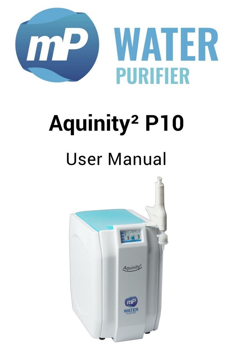
MP Aquinity 2 E User manual

membraPure GmbH
Wolfgang-Küntscher-Str.14
16761 Hennigsdorf
Germany
Tel.: +49 (0) 3302/201-20 0
Fax.: +49 (0) 03302/201-20 21
E-Mail: info@membrapure.de
Internet: www.membrapure.de
Service-Manual
Aquinity² E / Aquinity² P
ultra pure water system for the production of
ultra pure water water directly from tap water
with 35- or 70 liter permeate-tank

Rev. 2.1.5
Software V2.1.8; Firmware V0.13.8
Aquinity² is a registered trademark of membraPure GmbH. All rights reserved.
Subject to technical changes without prior notice.
Made in Germany.
Revision history
Rev.
Date
Description
2.0.0
2018-02-13
Initial version
2.1.1
2018-03-28
Bug fixes, added touchscreen calibration, simulation,
option pressure sensor
2.1.2
2018-04-10
Update chapter 6.5
2.1.3
2018-07-25
Update chapter 9.1.13; update picture SBC & PI
2.1.4
2018-11-21
Update dimension
2.1.5
2019-01-23
Update Table 5

Contents
1General .................................................................................................................. 1
1.1 About this manual................................................................................................ 1
1.2 Symbols used in this manual .............................................................................. 1
1.3 Liability and warranty........................................................................................... 2
1.4Copyright.............................................................................................................. 2
1.5 Spare parts........................................................................................................... 3
1.6 Disposal................................................................................................................ 3
2Safety.................................................................................................................... 4
2.1 Intended use......................................................................................................... 4
2.2 Contents of this manual ...................................................................................... 4
2.3Changes and modifications to the equipment.................................................... 5
2.4 User responsibility ............................................................................................... 5
2.5 Personal requirements......................................................................................... 5
2.6 Health and safety work........................................................................................ 6
2.7 Personal protective equipment (PPE) ................................................................. 6
2.8 Potential hazards................................................................................................. 6
3System Features.................................................................................................... 8
3.1 General ................................................................................................................. 8
3.2 Series overview .................................................................................................... 9
3.3 Technical data...................................................................................................... 9
3.4 Purification process........................................................................................... 10
3.4.1 EDI-cell in Aquinity² E .......................................................................................... 11
3.4.2 Conditioning Module in Aquinity² P..................................................................... 12
3.4.3 Purification elements in Aquinity² E and Aquinity² P.......................................... 12
3.5 TOC monitoring (TOC systems only)................................................................. 14
3.6 Hardware............................................................................................................ 15
3.6.1 Dispenser............................................................................................................. 15
3.6.2 Control PCB.......................................................................................................... 15
3.6.3 IEC Socket............................................................................................................ 16
3.6.4 Front- and side-panel........................................................................................... 16
4Installation and start up ....................................................................................... 17
4.1 Feed water requirements................................................................................... 17
4.2 Delivered parts ................................................................................................... 18
4.3 Hydrogen warning (for Aquinity² E)................................................................... 19
4.4 Setting up the system........................................................................................ 19

4.5Sealing plug........................................................................................................ 19
4.6 Connections ....................................................................................................... 20
4.7 Module attachment............................................................................................ 21
4.8 Vent filter attachment........................................................................................ 21
4.9 Sterile filter attachment..................................................................................... 22
4.10 Electrical connection...................................................................................... 22
4.11 Initial start-up ................................................................................................. 22
4.12 Normal start.................................................................................................... 24
5System Control Panel........................................................................................... 25
5.1 Normal operation mode..................................................................................... 25
5.2Tools................................................................................................................... 25
5.2.1 Exchanging consumables.................................................................................... 25
5.2.2 Exchanging UV-lamp (in the pure water section)................................................ 27
5.2.3 Exchanging UV submersible lamp (in the tank) .................................................. 27
5.2.4 Change all consumables ..................................................................................... 28
5.2.5 Exporting Data ..................................................................................................... 28
5.2.6 Prod. to max level ................................................................................................ 29
5.2.7 Disinfection.......................................................................................................... 29
5.2.8 Process visualization (system-status)................................................................ 30
5.2.9 Venting UPW........................................................................................................ 31
5.3 History................................................................................................................ 31
5.3.1 Warning messages .............................................................................................. 31
5.3.2 Graphical values .................................................................................................. 31
5.3.3 Logfile .................................................................................................................. 32
5.4 User setup .......................................................................................................... 32
5.4.1 Limits setup ......................................................................................................... 32
5.4.2 System time settings........................................................................................... 33
5.4.3 Reset timers(manually) ....................................................................................... 33
5.4.4 Operating hours ................................................................................................... 34
5.4.5 Manual stand by .................................................................................................. 34
5.5 Errors and Countermeasures............................................................................. 35
6Care and maintenance.......................................................................................... 37
6.1 Intervals.............................................................................................................. 37
6.2 Replacement of sterile-filter .............................................................................. 37
6.3 Modul replacement............................................................................................ 38
6.4 Replacement of the UV-lamp............................................................................. 39

6.5 Replacement of UV-submersible-lamp.............................................................. 40
6.6 Replacement of ultrafiltration module .............................................................. 41
6.7 Disinfection (UF-systems only) ......................................................................... 41
6.8 Replacement of reverse osmosis module......................................................... 43
6.9 P&I scheme (Aquinity² E)................................................................................... 44
6.10 P&I scheme (Aquinity² P)............................................................................... 45
6.11 Consumables.................................................................................................. 46
6.12 System update ............................................................................................... 46
7Users FAQ’s ......................................................................................................... 48
8Contact................................................................................................................ 48
9Service setup ....................................................................................................... 49
9.1.1 Adjustment conductivity sensors Q and temperature T ..................................... 49
9.1.2 Limit setting of conductivity sensors.................................................................. 50
9.1.3 Tank setup ........................................................................................................... 50
9.1.4 Read operating hours .......................................................................................... 51
9.1.5 Limit operating hours .......................................................................................... 51
9.1.6 Command line...................................................................................................... 51
9.1.7 System Info. (system-information)...................................................................... 52
9.1.8 First start ............................................................................................................. 53
9.1.9 Direct access ....................................................................................................... 53
9.1.10 Reset configuration ............................................................................................. 54
9.1.11 Reset calibration.................................................................................................. 54
9.1.12 Flushing, disinfection timer................................................................................. 54
9.1.13 Editor .mcf-file ..................................................................................................... 55
9.1.14 Touchscreen calibration...................................................................................... 56
9.2 Conductivity measuring amplifier ..................................................................... 57
9.2.1 Calibration of the conductivity and temperature measurement ......................... 57
9.3 Control board ..................................................................................................... 59
9.4 Single board computer ...................................................................................... 60
9.5 Software parameters ......................................................................................... 61
9.5.1 Configuration file (config.mcf) ............................................................................ 61
9.5.2 Calibration file (calib.mcf) ................................................................................... 63
9.5.3 Operating hours file (op_hour.dat) ...................................................................... 64
10 Services FAQ’s..................................................................................................... 64

General
membraPure GmbH
Wolfgang-Küntscher-Str.14
16761 Hennigsdorf
Germany
Tel.: +49 (0) 3302/201-20 0
Fax.: +49 (0) 03302/201-20 21
E-Mail: info@membrapure.de
Internet: www.membrapure.de
page 1
1General
1.1 About this manual
This manual describes how to use the equipment safely and correctly. When operating this
equipment, it is essential that the user adhere to the safety and operating instructions
included in the manual. Local safety and general safety regulations should also be followed
when using this equipment.
Before using the equipment, the user must read the entire manual, particularly the section
on safety and the relevant safety warnings. The user must fully understand the instructions
before operating the equipment.
The user manual is a part of the equipment. It must be kept close to the equipment and be
accessible at all times for all users. Should the equipment be passed on to a third party, the
manual must also be passed on to the third party.
1.2 Symbols used in this manual
Issues relevant to safety are characterized in this manual according to the following
symbols. These warnings must be observed in order to operate the equipment safely and
avoid accidents, damage or injury.
Risk of serious or fatal injury:
This symbol alerts the user to potential serious or fatal injuries. Do not operate
the equipment until you have completely understood the instructions and
proceed accordingly.
Risk of electric shock:
This symbol alerts the user to the presence of un-insulated electric power that
has the potential to cause serious or fatal injuries. Do not operate the equipment
until you have completely understood the instructions and proceed accordingly.
All maintenance work must be performed by qualified service personnel.
Important note:
This symbol alerts the user to potential sources of malfunctions or damage to
the equipment if operated improperly.

General
membraPure GmbH
Wolfgang-Küntscher-Str.14
16761 Hennigsdorf
Germany
Tel.: +49 (0) 3302/201-20 0
Fax.: +49 (0) 03302/201-20 21
E-Mail: info@membrapure.de
Internet: www.membrapure.de
page 2
Important reference to the manual:
It can be dangerous to undertake work on those parts of the system, labeled
by this symbol, unless the manual has been read and understood.
Advice:
This symbol alerts the user to advice on efficient and trouble-free operation.
1.3 Liability and warranty
The manufacturer of this product has many years of experience and expertise in the field of
water treatment technology. This manual has been written based on current safety code
legislation and state-of-the-art technology.
The user manual must be kept close to the equipment and available at all times for anyone
intending to use the equipment.
The user manual must be read before any work is carried out using the equipment! The
manufacturer does not accept liability for damage or faults that arise due to disregard for
the instructions in the manual.
The text and diagrams depicted in this manual do not necessarily match the equipment you
have received. The diagrams and images are not on a scale of 1:1.
The equipment delivered to you may be slightly different to the equipment described and
depicted here due to special features, additional options or changes in technology. If you
have any questions, please contact the manufacturer.
We reserve the right to make technical changes to the product and further develop it in
order to improve its functionality.
1.4 Copyright
This manual must be treated as a confidential document. It is only intended for use by
those operating the equipment.
All contents of this manual –text, diagrams, images etc. –are protected by copyright law
and industrial property rights. Anyone found violating these rights will be prosecuted.
The manual may not be passed on to third parties, copied –either in part or whole –or
used for any other purpose without the express and written consent of the manufacturers.
Anyone found violating these copyright laws must pay compensation. The manufacturer
may also prosecute.

General
membraPure GmbH
Wolfgang-Küntscher-Str.14
16761 Hennigsdorf
Germany
Tel.: +49 (0) 3302/201-20 0
Fax.: +49 (0) 03302/201-20 21
E-Mail: info@membrapure.de
Internet: www.membrapure.de
page 3
We reserve the right to exercise all industrial protection rights.
1.5 Spare parts
Only use original spare parts supplied by the manufacturer.
The wrong or faulty spare parts can lead to damage, malfunction or a complete
breakdown of the equipment.
All guarantees, warranties, service, damage and liability claims against the manufacturer,
the manufacturer’s representatives and dealers become null and void if unauthorized spare
parts are used in the equipment.
1.6 Disposal
If no return or disposal contract has been agreed on, please dispose of the disassembled
components as follows:
Recycle scrap metal parts,
Recycle plastic parts,
Dispose of other components according to the material.
Electrical and electronic scrap and components, lubricants and other process
materials must be treated as hazardous waste and can only be disposed of by
authorized waste disposal facilities.

Safety
membraPure GmbH
Wolfgang-Küntscher-Str.14
16761 Hennigsdorf
Germany
Tel.: +49 (0) 3302/201-20 0
Fax.: +49 (0) 03302/201-20 21
E-Mail: info@membrapure.de
Internet: www.membrapure.de
page 4
2Safety
At the time this equipment was developed and produced, it complied with current state-of-
the-art technology and is accepted as reliable and safe.
The equipment can represent a hazard if it is operated by untrained personnel. Improper
operation or operation not in accordance to the manual may pose a hazard.
The section on safety provides an overview of all the important issues relevant to personal
safety and safe, trouble-free operation of the system.
The other sections of the manual also contain specific safety warnings and warning
symbols that highlight possible hazards. Please comply with the pictograms, signs,
markings and inscriptions on the equipment. These must not be removed and must always
be visible.
2.1 Intended use
The equipment is only safe if operated as intended and described by the instructions in this
manual.
Any form of use or operation other than the intended use is improper and
prohibited.
Claims of any kind made against the manufacturer or the manufacturer’s representatives
are null and void if the equipment is not operated as intended.
The operating company is liable for all damages caused by improper use.
The intended use is described in the manual and includes compliance with the operating
conditions.
The equipment may only be operated with the parts supplied.
2.2 Contents of this manual
Anyone intending to work with or use the equipment must read and understand the user
manual before operating the equipment. This applies even if the user has already operated
similar equipment or devices of a similar nature or has been trained by the manufacturer.
Reading and understanding the manual is the only way to protect against potential hazards,
prevent mistakes and operate the equipment safely and efficiently.

Safety
membraPure GmbH
Wolfgang-Küntscher-Str.14
16761 Hennigsdorf
Germany
Tel.: +49 (0) 3302/201-20 0
Fax.: +49 (0) 03302/201-20 21
E-Mail: info@membrapure.de
Internet: www.membrapure.de
page 5
We recommend that the operating company obtain written confirmation from each user
that he/she has read and understood the manual.
2.3 Changes and modifications to the equipment
In order to avoid hazards and ensure that the equipment operates at its best, do not make
any changes or modifications to the equipment that have not been expressly authorized by
the manufacturer.
Ensure that all pictograms, signs, markings and inscriptions on the equipment are always
visible and never removed. Damaged, missing or illegible pictograms, signs, markings and
inscriptions must be replaced immediately.
2.4 User responsibility
The user manual must be kept close to the equipment and available at all times for anyone
intending to use the equipment.
The equipment may only be operated in a technically flawless and safe state. The
equipment must be checked for damage before each start-up.
The instructions in the manual must be followed completely and without restriction!
When operating this equipment, it is essential that the user adhere to the safety and
operating instructions provided. The local accident prevention regulations, general safety
regulations and relevant environmental protection legislation must also be followed.
The operating company and the authorized personnel within that company are responsible
for properly operating the equipment. The operating company must define who is
responsible for installing, operating, servicing and cleaning the equipment.
The operator is obliged to perform an operations manual. Otherwise the warranty expires.
2.5 Personal requirements
Only authorized and trained personnel are allowed to operate the equipment. The user must
have been instructed about the potential hazards involved in using the equipment.
Authorized personnel are persons with sufficient training, knowledge, experience and
understanding of the relevant regulations to be able to assess the task given to him/her and
identify potential hazards.
If a potential user does not have sufficient knowledge at his/her disposal, this person must
be trained/qualified before using the equipment.

Safety
membraPure GmbH
Wolfgang-Küntscher-Str.14
16761 Hennigsdorf
Germany
Tel.: +49 (0) 3302/201-20 0
Fax.: +49 (0) 03302/201-20 21
E-Mail: info@membrapure.de
Internet: www.membrapure.de
page 6
It must be clear who is responsible for equipment installation, operation, maintenance and
service. These competencies must be clearly defined and conformed to in order to prevent
any uncertainties that may compromise safety.
Only reliable personnel may work with and operate the equipment. Do not allow anyone to
operate the equipment in a way that compromises the safety of others, poses a hazard to
the environment or damages the equipment.
No one under the influence of drugs, alcohol or medication that impairs the ability to
respond/react is allowed to operate the equipment.Please consider all other directives
related to qualification when selecting potential users.
The user must ensure that unauthorized personnel keep a safe distance from the
equipment.
Personnel must report to the operating company immediately if any changes become
apparent which may impair the safe operation of the equipment.
2.6 Health and safety work
Follow the safety and operating instructions given in this manual in order to avoid causing
harm or damage to persons and property while working with and on the equipment. If these
instructions are not observed, the equipment may become damaged or destroyed or may
harm persons.
The manufacturer is not liable for damage or compensation if the safety and operating
instructions in this manual or the local accident prevention regulations and general safety
regulations are not observed.
2.7 Personal protective equipment (PPE)
When working with this equipment, please wear goggles or another form of
protective eyewear.
2.8 Potential hazards
The subsequent equipment design and execution corresponds to state-of-the-art
technology and regulations at the time of manufacture.
The equipment is safe for use, provided it is operated as intended. A minimal residual risk
cannot be eliminated completely.
The equipment is run at high electrical voltage.

Safety
membraPure GmbH
Wolfgang-Küntscher-Str.14
16761 Hennigsdorf
Germany
Tel.: +49 (0) 3302/201-20 0
Fax.: +49 (0) 03302/201-20 21
E-Mail: info@membrapure.de
Internet: www.membrapure.de
page 7
Electricity in the equipment can lead to serious injuries. The equipment presents
a danger to life if the insulation or individual components become damaged.
Switch off the main power switch before carrying out maintenance, cleaning or repair work
and ensure that it cannot be switched on again while carrying out this work.
Eliminate all voltage from the equipment when working on the electrical equipment.
Do not remove or deactivate any safety equipment.
The manufacturer does not take any responsibility for injuries caused by improper use of
the system.

System Features
membraPure GmbH
Wolfgang-Küntscher-Str.14
16761 Hennigsdorf
Germany
Tel.: +49 (0) 3302/201-20 0
Fax.: +49 (0) 03302/201-20 21
E-Mail: info@membrapure.de
Internet: www.membrapure.de
page 8
3System Features
3.1 General
The Aquinity² system is designed for the production of analytical grade ultra pure water
from drinking water public municipal supply. The system combines the advantages of
reverse osmosis with final purification. Permeate from the reverse osmosis is temporarily
stored inside a tank. In a purification section ultra pure water with permanent highest
quality will be produced, supplied with the dispenser at the front side of the unit.
Currently recorded data and warning messages will be displayed on the system monitor.
All components of the system are assembled in a designed plastic housing. The housing
can easily be opened for the access of the modules. The system corresponds to the latest
technology and to recent safety regulations. It can be installed and put into operation
without the help of customer service.
Figure 1: Aquinity²E or P
screen
dispenser
tank

System Features
membraPure GmbH
Wolfgang-Küntscher-Str.14
16761 Hennigsdorf
Germany
Tel.: +49 (0) 3302/201-20 0
Fax.: +49 (0) 03302/201-20 21
E-Mail: info@membrapure.de
Internet: www.membrapure.de
page 9
3.2 Series overview
Aquinity² E
model
UV-
reactor
UF-
module
TOC-
monitoring
Art.-No.:
(35L-tank)
Art.-No.:
(70L-tank)
Reagent
○
○
○
114-0053
114-0063
Analytical
●
○
○
114-0054
114-0064
LifeScience
●
●
○
114-0055
114-0065
Analytical TI
●
○
●
114-0058
114-0068
LifeScience TI
●
●
●
114-0059
114-0069
Aquinity² P
model
UV-
reactor
UF-
module
TOC-
monitoring
Art.-No.:
(35L-tank)
Art.-No.:
(70L-tank)
Reagent
○
○
○
114-0050
114-0060
Analytical
●
○
○
114-0051
114-0061
LifeScience
●
●
○
114-0052
114-0062
Analytical TI
●
○
●
114-0056
114-0066
LifeScience TI
●
●
●
114-0057
114-0067
Table 1: Series-overview
3.3 Technical data
Aquinity² E
RE
AL
LS
AL TI
LS TI
Product water specifications
product water flow
L/min
up to 2
conductivity at 25°C
µS/cm
0,055
resistivity at 25°C
MΩcm
18,2
TOC-concentration
ppb
< 10
< 1
< 5
< 1
< 5
Endotoxin-concentration
EU/ml
n/a
n/a
< 0,001
n/a
<0,001
System specifications
shipping weight (35L-tank)
kg
shipping weight (70L-tank)
kg
power supply
V
100 … 240
Hz
50 / 60
dimension (W/D/H)
cm
35 / 54 / 51
dimension +dispenser
(W/D/H)
cm
35 / 75 / 63
Table 2: Technical Data

System Features
membraPure GmbH
Wolfgang-Küntscher-Str.14
16761 Hennigsdorf
Germany
Tel.: +49 (0) 3302/201-20 0
Fax.: +49 (0) 03302/201-20 21
E-Mail: info@membrapure.de
Internet: www.membrapure.de
page 10
3.4 Purification process
Figure 2: Purification diagram of Aqunity² E (top), Aquinity² P (bottom)
Aquinity² E
Aquinity² P

System Features
membraPure GmbH
Wolfgang-Küntscher-Str.14
16761 Hennigsdorf
Germany
Tel.: +49 (0) 3302/201-20 0
Fax.: +49 (0) 03302/201-20 21
E-Mail: info@membrapure.de
Internet: www.membrapure.de
page 11
When the system starts in normal operation mode, the inlet valve opens and the reverse
osmosis pump starts. It will be closed and the pump will be stopped, when the permeate
tank is completely full.
The pretreatment module ProPak-R10 is a combination of filtration and adsorption via
highly pure activated carbon. Chemicals like chlorides, insecticides, pesticides, and
herbicides and particles larger than 5 micrometer are detained.
The RO pump increases the pressure for the reverse osmosis process. The reverse osmosis
module remove about 98% of the salt content from the water. Moreover nearly all bacteria,
viruses, heavy metal complexes as well as organic molecules with a molecular weight
higher than 300 daltons are rejected. The purified water is called permeate, the waste reject
water is called concentrate. The concentrate water is rejected to drain via flow limiter.
The conditioning module is filled with ion exchanger resin. This module removes hardness
ions from the water to protect the EDI cell.
The permeate conductivity is monitored with a sensor and displayed on the system
monitor. If the conductivity exceeds a preset limit, a warning message will be displayed and
the permeate will be drained.
3.4.1 EDI-cell in Aquinity² E
The EDI cell removes salt contents from the water by the principle of electro-deionization.
Ions pass a membrane into a concentrate chamber and are rinsed out by a flushing stream
(see Figure 3: schematic diagram of the EDI cell). The purified water is called electro-
deionized water. The EDI-electro-deionized permeate containing accumulated ions led to
drain is called sole.
The conductivity of this EDI-deionized permeate is monitored with a sensor. The measured
value is displayed in the unit µS/cm. If the conductivity exceeds a preset limit, a warning
message will be displayed and the solenoid valve will be closed. The solenoid valve will be
opened and the EDI-deionized permeate flows to drain.
The system must be connected to a tank with level control to regulate the production and
tank filling. When the tank is completely full, the production will be stopped. When the level
falls below 75%, the production will be started again and the tank will be filled. If the level
falls below the minimum filling of 15%, the circulation pump will be stopped to prevent its
running dry.

System Features
membraPure GmbH
Wolfgang-Küntscher-Str.14
16761 Hennigsdorf
Germany
Tel.: +49 (0) 3302/201-20 0
Fax.: +49 (0) 03302/201-20 21
E-Mail: info@membrapure.de
Internet: www.membrapure.de
page 12
Figure 3: schematic diagram of the EDI cell
The conductivity will be decreased by an electro-chemical process within the EDI cell. The
ion exchange chamber provide for a salt removal from the water. Concentrate will be
drained. The conductivity value of the ultra pure water will be lower than 0.1 µS/cm.
3.4.2 Conditioning Module in Aquinity² P
The conditioning module is filled with mixed-bed ion exchanger resin. It is used to reduce
the salt concentration of the permeate in order to produce deionized water.
The conductivity of this deionized water is monitored with a sensor and displayed on the
system monitor in order to check the functionality of the conditioning module. If the
conductivity exceeds a preset limit, a warning message will be displayed and the
conditioning module should be changed.
The system must be connected to a tank with level control to regulate the production and
tank filling. When the tank is completely full, the production will be stopped. When the level
falls below 75%, the production will be started again and the tank will be filled. If the level
falls below the minimum filling of 15%, the circulation pump will be stopped to prevent its
running dry.
3.4.3 Purification elements in Aquinity² E and Aquinity² P
The UV submersible lamp inside the tank protects the stored water against microbial
contamination by direct UV radiation.

System Features
membraPure GmbH
Wolfgang-Küntscher-Str.14
16761 Hennigsdorf
Germany
Tel.: +49 (0) 3302/201-20 0
Fax.: +49 (0) 03302/201-20 21
E-Mail: info@membrapure.de
Internet: www.membrapure.de
page 13
The tank will be vented with sterile air via CO2trap ventilation filter.
Stored permeate can be drawn off via tap valve at the front of the tank.
With respect to safety, a float switch is provided. This protects the tank from overflowing
liquid levels.
The circulation pump feeds the water into the polishing section with circulation.
UV systems only:Inside the UV reactor free hydroxyl radicals (OH-) are produced. These
radicals oxidize remaining organic materials in the water.
TOC systems only: The TOC concentration is monitored with a sensor and will be displayed
on the system screen as TOC.
The polisher module UPW-Pak Art.-No.: 190-0087 is filled with high grade mixed bed resins
in semiconductor quality to reduce mainly the salt content. For inorganic applications
which do not require a low level TOC the polisher module UPW-Pak Art.-No.: 190-0088 can
be used.
UF systems only: The ultrafiltration module removes endotoxins and viruses from the water.
Ultrafiltrated water is almost free of RNase, DNase and DNA. If water will be taped, the
module will automatically be flushed via flushing valve.
Product water conductivity is monitored with a sensor and displayed on the system
monitor. If the conductivity exceeds a preset limit, a warning message will be displayed.
A sensor monitors the temperature of the product water. If the temperature exceeds the
limit of 40°C, a warning message will be displayed.
The sterile filter protects the system against microbial contamination by filtration of
particles larger than 0.2 µm.
Product water will be supplied via dispenser. For a small volume of product water the
dispenser button has to be pressed slightly, for a higher volume the dispenser can be
switched into permanent position.
A check valve keeps the circulation pressure constant and prevents a backflow of the
product water.

System Features
membraPure GmbH
Wolfgang-Küntscher-Str.14
16761 Hennigsdorf
Germany
Tel.: +49 (0) 3302/201-20 0
Fax.: +49 (0) 03302/201-20 21
E-Mail: info@membrapure.de
Internet: www.membrapure.de
page 14
3.5 TOC monitoring (TOC systems only)
By measuring the oxidized material with subsequent electronic evaluation, it is possible to
detect the TOC concentration (total organic carbon) of the product water.
The TOC-concentration is shown on the display.
Figure 4: example of the display Aquinity² E
Figure 5: example of the display Aquinity² P

System Features
membraPure GmbH
Wolfgang-Küntscher-Str.14
16761 Hennigsdorf
Germany
Tel.: +49 (0) 3302/201-20 0
Fax.: +49 (0) 03302/201-20 21
E-Mail: info@membrapure.de
Internet: www.membrapure.de
page 15
3.6 Hardware
3.6.1 Dispenser
Figure 6: Standard dispenser
The dispenser has a lock function to make water tapping easier. Moreover, the dispenser
will stay in a fixed position which has increased its flexibility (no draw back function) and
gives the user more comfort when tapping water. This has been set as a standard
dispenser for pure water system and memtap system (optional).
3.6.2 Control PCB
Water system has a control pcb which provides communication between main computer
system and analog- & digital-sensors. This pcb has been flashed with a firmware (Firmware-
Version 0.13.8) with a watchdog function. If there is any problem with sensor reads, this
control pcb will restart the system automatically after ca. 2 minutes
This manual suits for next models
1
Table of contents
Other MP Water Filtration System manuals
Popular Water Filtration System manuals by other brands
Kasco
Kasco ZP3 Use and maintenance instructions

GE
GE GXK255TBN Owner's Manual & Installation Instructions

Price
Price FFU series user manual

3M
3M ScaleGard Blend Series Change-out Instructions

InterFlo
InterFlo IF-14 Owner's manual & installation guide
Beko
Beko CLEARPOINT S040 Instructions for installation and operation
ACO
ACO Oleosmart-C-OST Operating and maintenance instructions
Sharp
Sharp FZ-425SEF Operation manual

Valrom Industrie
Valrom Industrie aquaPUR 4 UF instructions

Blue Mountain
Blue Mountain Rain Harvesting WFRW03 installation guide
ubbink
ubbink FiltraClear 4500 Basic Set EU manual
Culligan
Culligan Aquasential Select Plus Iron-OX5 owner's guide
